Adjustments.
Tuning Adjustment
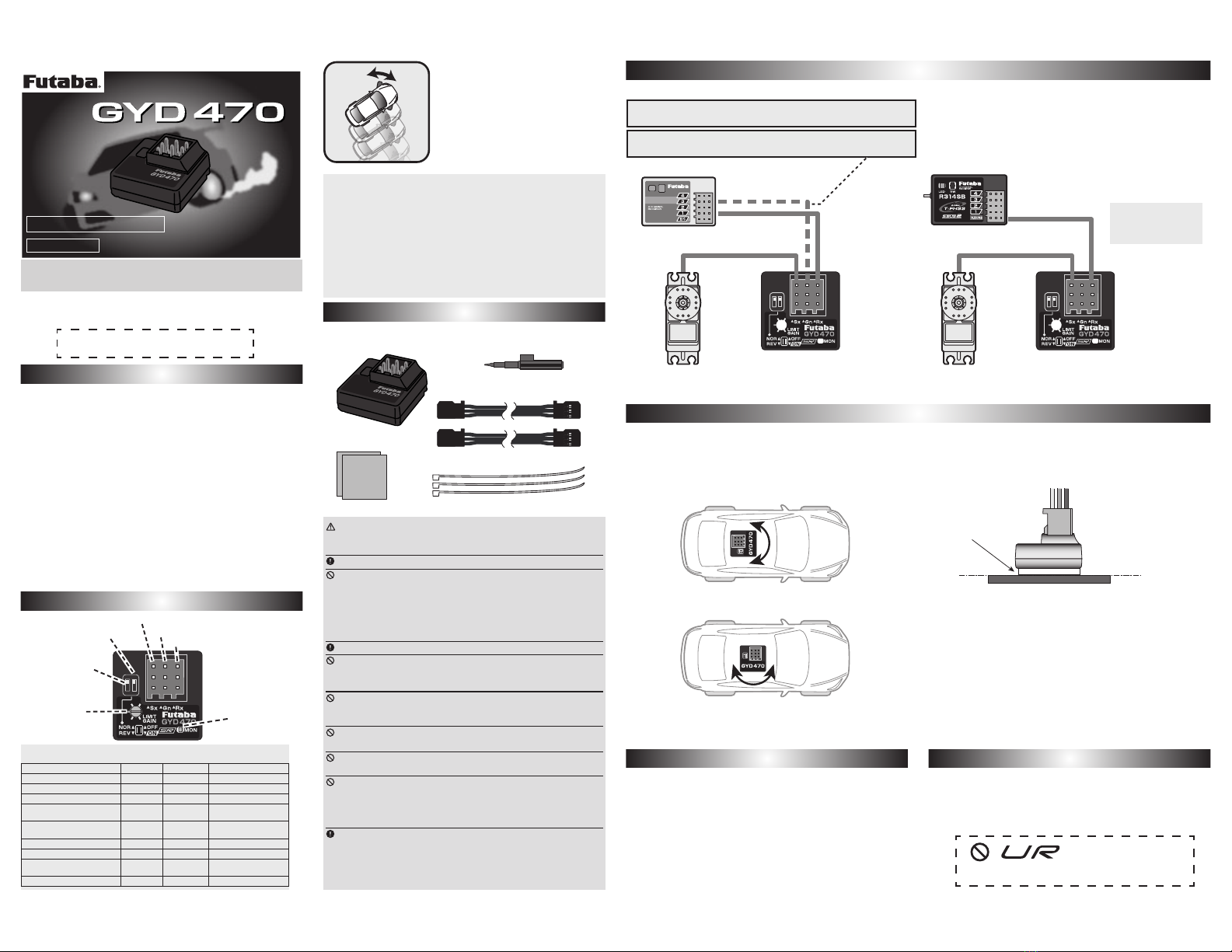
S.BUS System
AVCS / NORMAL Modes
Setup before a run [ Remote gain use ]
Gain adjustments are carried out with a transmitter.
Follow this procedure when the port 2 of gyro and gain CH of the
receiver are connected. (or with S.BUS connection)
1Runthecarinthegyrooff(gyrogain0%)andadjust
thesteeringtrim(subtrim).
2Selecttheappropriatesettingforthesteeringservothat
youareusing.ServoselectionswitchofGYD470 should
bemovedto SRmodeON orOFF.
*Donot useanormaldigitalservointheSRservomode(ON).The
servomaybe damaged.Useanormaldigital servoin theSR servo
mode(OFF).
3Turnonyourtransmitter'spower.Setthegyro
sensitivitytoabout70%attheNORMALorAVCSside
inaccordancewiththetransmitterinstructionmanual. The
<GAINCH><AVCS/NORMALModes>graphofthenext
pageisreferredto.
*Make the gain tuning adjustment after running the car and noting
the behavior.
4ReceiverON → TheGYD470requires3-5secondsto
initializewhenthepoweristurnedon.Donotmove
thecaranddonotmovethesteeringwheelduringthis
initializationorthegyromaynotinitializeproperly.Once
theinitializationprocesshasbeencompletedthesteering
servowillmove(alittle)severaltimesindicatingthatthe
GYD470isnowreadyforuse.Iftheneutralhasshifted,LED
willblinkorange.Inthatcase,itreboots.
5Movethesteeringwheeltotheleftandrightand
performadjustmentatthelimittrimmersothatthe
servooperationismaximumwithoutanybindofthe
controllinkageormechanicallimits.
Actually drive the vehicle and adjust the gyro sensitivity.
1Alwaysre-trimwiththegyrogainat0.
2InthisstateturnthereceiverpowerOFF → ON.The
neutralpositionismemorized.Steeringtrimmustnot
beperformedwhilethecarisrunning.
Thegyro has2 operatingmodes: NORMALmodeandAVCS
mode.IntheAVCSmode,gyrocontrolisfirmer.Thecarwill
holdheadingviathedriverscommands.
InNORMALmodethegyrowilltrytocountersteer,butstill
allowthecartodriftregardlessofpreviousheading.
Becausethefeelofoperationisdifferent,chooseyourfavorite
mode.
3CH(GAINCH)issetupwithreferencetothemanualofa
transmitter.NeutralpositionbecomesGAIN0%.Itisdivided
intoAVCSsideandNORMALside.CheckusingtheGYD470's
LED.
WhenPort2isnotusedforgain,andSBUS/SBUS2isnot
used,thetrimmerworksasthegainadjustmentshown
below.
Incaseoftherightslide
⇒Leftsteeringcontrol
Incaseoftherightslide
⇒Rightsteeringcontrol
AVCS NORMAL
Thegyrowilltrytoget
thecartogripinthe
driverssteering
direction.
Thegyrowilltryto
countersteerregardless
oftheangleofthecar.
0%
-55%
+55%
50%
50%
100%
100%
+110%
-110%
Endpointrate
Gain
NORMALside(LED:GREEN)
AVCSside(LED:RED)
Unlikeconventionalradiocontrolsystems,theS.BUSsystem
sendsoperating signalsfromthereceiverto agyroorother
S.BUScompatibledevicebydatacommunication.TheS.BUS
compatibledevice executesonlythosepartsof thisdatafor
thechannelssetbyitself.Forthisreasonmultipleservoscan
beconnectedtothesamesignalline.
TheS.BUSsystemrequiresadedicatedS.BUSreceiverand
S.BUSservo(gyro,etc.).
Ifthecaristurnedtotheleft
byhand → steeringgoesout
ontheright
<LimitTrimmerAdjustments>
Itadjuststothe
maximumoperationof
linkage.
Steeringwheelto
full
D/R(UPside)
Limittrimmer
Adjustments
Gyrosensitivityzero---LEDOFF
AVCSside---LEDred
NORMALside---LEDgreen
6Usingthegyrodirectionswitch,adjustthegyro
operatingdirection sothat steeringmovesalltheway
totherightwhenthecaristurnedtotheleft.Besuretoset
gyrooperatingdirectioncorrectlyorthecarwillnotrun.
[ When remote gain function is off ]
Adjust the gyro sensitivity with the GYD470 trimmer.
If the port 2 of gyro is not connected, remote gain is automatically
set to being inhibited. (S.BUS connection is excluded)
In this case, the limit trimmer is automatically changed to gyro
sensitivity setting trimmer.
/LPLWDGMXVWPHQWFDQQRWEHSHUIRUPHG$OLPLWLV¿[HGWRULJKW
and left.)
1Selecttheappropriatesettingforthesteeringservothat
youareusing.ServoselectionswitchofGYD470 should
bemovedto SRmode ON orOFF.
*DonotuseanormaldigitalservointheSRservomode(ON).Theservo
maybedamaged. Useanormal digitalservoin theSR servomode
(OFF).
2Gaintrimmerhalfwaytotheleft:NOMAL(green)or
right:AVCS(red)fromthe70%point.
3ReceiverON → TheGYD470requires3-5secondsto
initializewhenthepoweristurnedon.Donotmove
thecaranddonotmovethesteeringwheelduringthis
initializationorthegyromaynotinitializeproperly.Once
theinitializationprocesshasbeencompletedthesteering
servowillmove(alittle)severaltimesindicatingthatthe
GYD470isnowreadyforuse.Iftheneutralhasshifted,LED
willblinkorange.Inthatcase,itreboots.
4Usingthegyrodirectionswitch,adjustthegyro's
operatingdirection sothat steeringmovesalltheway
totherightwhenthecaristurnedtotheleft.Besuretoset
theoperatingdirectioncorrectlyorthecarwillnotrun.
● Trimmeroperation
*Sincethisgyroisalsoverysmall,theadjustmenttrimmerisalsoasmall
part.Alwaysoperatethetrimmerwiththeaccessoryminiscrewdriver
andwithoutapplyingunreasonableforce.
*Limit is symmetricalfrom the neutral
position. Only proceed with the limit
adjustment after completing the trim
adjustment.
Gyro Sensitivity and mode Switching
Gyro Sensitivity and mode Switching
Whentheremotegainfunctionisnotused,theclockwise
directionfromthecenterofthesensitivitysettingtrimmer
isthe AVCSmode andthe counterclockwisedirectionisthe
NORMALmode.Atthecenterpositionthesensitivitybe-
comeszeroandwhenthetrimmeristurnedfullytotheleftor
right,thesensitivitybecomes100%.
The sensitivitysettingcriteriabyendpointisshownin the
figurebelow.
<GAIN CH >
Gyrosensitivityzero---LEDOFF
AVCSside---LEDred
NORMALside---LEDgreen
Whentheremotegainfunctionisused,NORMALandAVCS
modeswitchingisperformedinaccordancewiththedirec-
tionofoperationofthetransmitter'sremotegainchannel.
Atthe+rateside,theAVCSmodeisselectedandatthe‒
rateside, the NORMALmodeisselected.Thesensitivityis
changedbyadjustingtheendpointrate.
0%
NOMAL70%
AVCS70% AVCS100%
0%
AVCS50%
FUTABA CORPORATION
Hobby Radio Control Business Center Sales & Marketing Department
<DEXWVXND&KRVHLPXUD&KRVHLJXQ&KLEDNHQ-DSDQ
7(/)$; ©FUTABA CORPORATION 2023, 4 (3)