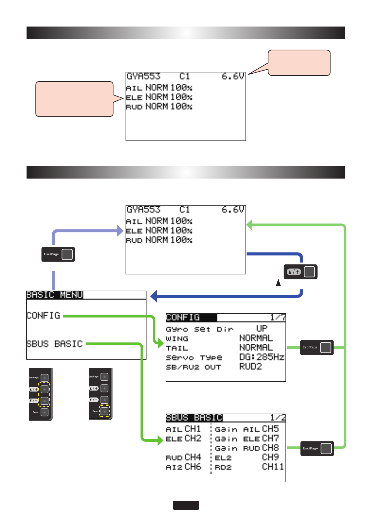
Press the [Enter] and [Esc/Page] keys next
turn ON
Press the [ /+] and [ /-] keys next turn ON
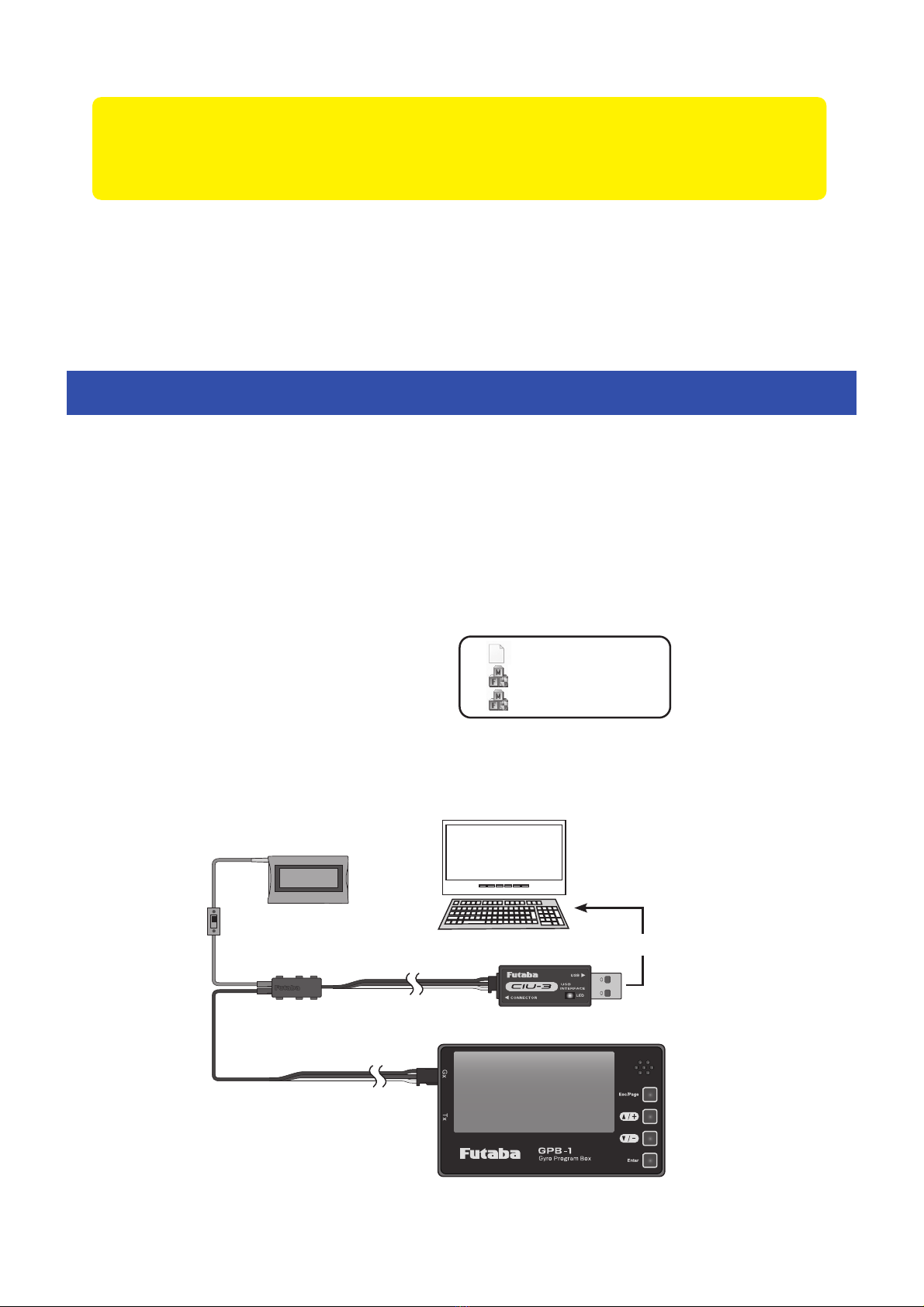
When using the CIU-3
When using the CIU-2
CIU-3
CIU-2
Double-
click
PC
6WDUWDQH[HFXWDEOH¿OHE\D
PC.
GPB-1
5.
When using the CIU-3, hold
down the [Enter] and [Esc/
Page] keys of the GPB-1 and
turn on the power. Release the
[Enter] and the [Esc / Page]
keys when the backlight of the
screen lights up.
When using the CIU-2, hold down
the [ /+] and [ /-] keys of the GPB-
1 and turn on the power. Release
the [ /+] and [ /-] keys when the
backlight of the screen lights up.
Click[OK]
Wait for about 50 seconds - 5 minutes.
Click[WRITE]
OK
WRITE
When using the CIU-2
When using the CIU-3
Don't turn off the power !
CAUTION
Do not turn off the power
or remove the battery while
updating. GPB-1 may be dam-
aged.
Updater(Highspeed).exe
Updater(Lowspeed).exe
PC side GPB-1 side
Click[OK]
If and error message appears,
try redoing the update form the
beginning.
Wait for about 50 seconds - 5 minutes.
Error
6.
Turn off the power after
the completed message
"SUCCESS"appears.
7.
Check the GPB-1 program
version on the Information
screen.
8. Be sure to check each setting
and check the operation
before using.
If the cable disconnects or a contact
failure occurs during the update, the
update stops halfway. In that case,
please try updating again from the be-
ginning.
If the GPB-1 fails to update or does not
start, please have it serviced.
PC side GPB-1 side