Adjustments Flight Adjustments
AVCS / NORMAL Mode
● A trimmer's operation
*Since the trimmer is small and delicate, operate
it by gently using the provided mini screwdriver.
Setup before a ight [ Remote gain use ]
Adjusting gain with the transmitter.
When S.BUS connection or the gyro gain CH of the port 2 of a
gyro and a receiver is connected.
1Settheservoselectionswitchtothesettingforyourtailrotor
servo.Seechartbelow.
2Setupyourtransmitterbyfollowingthedirectionsinthe
manual.Gyrogainissetupto50%byAVCS.Pleasereferto
thegraph,AVCS,NORMALorwhenunclear.Itjudgesbythe
LEDontheGY430.AVCS:RedNORMAL:Green
3ReceiverON → TheGY430requires3-5secondstoinitialize
whenthepoweristurnedon.Donotmovethehelicopterand
donotmovetherudderstickduringthisinitializationorthe
gyromaynotinitializeproperly.Oncetheinitializationprocess
hasbeencompletedtherudderservowillmoveseveraltimes
indicatingthattheGY430isnowreadyforight.Iftheneutral
hasshifted,LEDwillblinkorange.Inthatcase,itreboots.
4Movetheruddersticktotheleftandrightandmakeadjustments
withthelimittrimmer.Adjustformaximumtravel,makingsurethe
servohorndoesn'thitthelinkage.
[ Remote gain not use ]
Adjusting gain with the GY430 trimmer.
When not using an S.BUS connection and port 2 is not connected.
In this case, a limit trimmer is automatically changed by the gyro
gain setting trimmer. A limit is xed by 50 degrees of right and
left.
Adjustthetransmitterandgyrowhilerepeatedlytakingoand
landingandwiththeaircraftontheground.
Transmitter adjustments must not be made while ying
because it is dangerous.
1Setthesensitivitytothepositionatwhichhuntingdoesnot
occurduringhoveringandight.
2Adjustthehoveringandflightruddereffectusingthe
transmitter'sD/RorAFRfunction.
* Do not adjust with the End Point (ATV) function. If the End Point (ATV)
function is used, trimming may change.
AVCS100%
NORMAL100%NORMAL50%
LIMIT
GAIN
0%
AVCS50%
<A gain trimmer's work >
<GAIN CH >
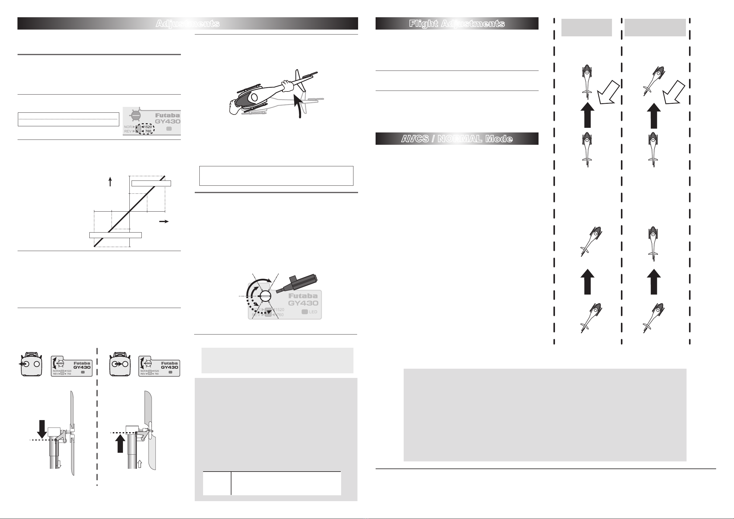
Operation in AVCS mode
If the rudder stick is operated or the helicopter is moved when the
helicopter was stopped during operation in the AVCS mode, the servo
will not return to the neutral position even if the rudder stick is re-
turned to the neutral position, and when the rudder stick is moved, the
rudder servo controls operation until the tail reaches the maximum
point. This is caused by addition of an integration function as an
AVCS mode operation and is not an abnormality. In actual ight, the
gyro constantly monitors movement of the tail and controls the servo
so that movement of the tail is stopped.
AVCS mode servo neutral position check method;
If the rudder stick or the helicopter was moved in the AVCS mode, the servo
will not return to its original neutral position. When the power is turned on,
the servo will return to the neutral position. The servo neutral position can
also be checked by the following method.
Neutral
position
Move the rudder stick 3 times to its full stroke to the left
and check method right at an internal of within 1 second
and immediately return the rudder stick to the neutral
position. The servo moves to the neutral position about 1
second later.
NORMAL mode sends control signals to the rudder servo only
when the tail of the helicopter moves. When the tail stops mov-
ing, the control signal from the gyro becomes zero. Conversely,
the AVCS mode continues to send control signals to the servo
even when the tail of the helicopter stops moving. The following
sequentially describes the NORMAL mode and the AVCS mode.
Operation of NORMAL mode
Basic operation is described by considering the case when the
helicopter is hovering under cross-wind conditions. With a nor-
mal mode, when the helicopter encounters a cross-wind, the
force of the cross-wind causes the tail of the helicopter to drift.
When the tail drifts, the gyro generates a control signal that stops
the drift. When the tail stops drifting, the control signal from the
gyro becomes zero. If the cross-wind continues to cause the tail
to drift in this state, the "stop" operation is repeated until the tail
faces into the winds. This is called the "weathervane" effect.
Operation of AVCS mode
Conversely, with an AVCS mode, when the helicopter encoun-
ters a cross-wind and the tail drifts, a control signal from the gyro
stops the drift. At the same time, the gyro computes the drift an-
gle and constantly outputs a control signal that resists the cross-
wind. Therefore, drifting of the tail can be stopped even if the
cross-wind continues to effect the helicopter. In other words, the
gyro itself automatically corrects(auto trim) changes in helicopter
tail trim by cross-wind. Considering operation of an AVCS mode,
when the tail of the helicopter rotates, the servo also rotates in
accordance with the angle of rotation of the tail. When the tail
stops rotating, the servo judges that it has stopped in that posi-
tion. This is the auto trim function.
InAVCSoperation
mode
InNORMALoperation
mode
Hoveringinacrosswind.
Thetailwilldrift.
AVCSisworking
properlyduring
acrosswind.
Ifitstartsrightdrift Ifitstartsrightdrift
Aheadturnstoa
directionofmovement
automatically.
Ifnoleftrudderinput
isgiven,themachine
willdrifttotheright.
Cross
wind Cross
wind
Hovering High-speedflight
0%
-50%
+50%
50%
50%
100%
100%
+100%
-100%
Endpointrate
Gain
NORMALside(LED:GREEN)
AVCSside(LED:RED)
Please take a look at both the directions for the helicopter as well
as the transmitter.
LIMIT
GAIN
LIMIT
GAIN
Holdtherudder
stickfullleft.
Adjusttheleftlimit
withthetrim.
Holdtherudder
stickfullright.
Adjusttheright
limitwiththetrim.
Adjustthelinkageset
uptogetthe
maximumthrow.
Adjustthelinkageset
uptogetthe
maximumthrow.
Bottomviewofthe
tailsectionwiththe
rudderstickfullleft.
Bottomviewofthe
tailsectionwiththe
rudderstickfullright.
【Adjustment at the limit trimmer】
【Preflight check】
Helicopter is turned to the Left ⇒Rudder operates on the
Right.
*This check is performed in the state where an engine (motor)
never starting.
5IftherudderservomovestotheRightwhenthenoseofthe
helicoptermovestotheLeft,thegyrodirectioniscorrect.If
therudderservomovestotheLeft,switchthedirectionusing
theGyro Direction Switch.
If you try to fly the helicopter while the gyro direction is incorrect,
when the rotor rotates clockwise, the helicopter nose will yaw to the
Left and cause an extremely dangerous situation.
First,wesuggesttostartwithAVCSsetto50%.
FUTABA CORPORATION
1080 Yabutsuka, Chosei-mura, Chosei-gun, Chiba-ken, 299-4395, Japan
Phone: +81 475 32 6982, Facsimile: +81 475 32 6983
©FUTABA CORPORATION 2012, 6 (1)
What is S.BUS?
Unlike conventional radio systems, the S.BUS system uses
data communication to transmit control signals from a
receiver to a servo, gyro, or other S.BUS compatible device.
This data includes commands such as “move the channel 3
servo to 15 degrees, move the channel 5 servo to 30 degrees”
to multiple devices. The S.BUS devices execute only those
commands for their own set channel. For this reason, it can
be used by connecting multiple servos to the same signal
line.
* Set the channel at the S.BUS servos by using an SBC-1 channel changer or a CIU-2 USB serial interface.
* Can also be used together with conventional servos. However, conventional servos cannot be used by the S.BUS output.
* When using servos with a remote battery pack, use S.BUS Hub with Cable (2-way/remote battery pack use).
Please refer to the instruction manual of S.BUS Hub with Cable (2-way/remote battery pack use) for the connection method.
Please turn on the power supply of the transmitter rst without fail, and, next, turn on the receiver if you use S.BUS. Moreover, please use it
after it conrms the operation without fail. Otherwise, the S.BUS communication cannot be judged and it is likely to malfunction.
The wiring for the S. BUS servo is replaced at power supply OFF. If you replace the wiring in power supply ON, S. BUS communications
cannot be judged, and it seems to malfunction.
Similarlytheprocedureof1.3.5 isfollowed.
LIMIT
GAIN
1520uS:BLS254,BLS257,S9254,S9257,etc.
760uS:BLS256HV,BLS251,S9256,S9251


