Eastern Voltage Research microBrute DRSSTC Tesla Coil KiT User manual

microBrute DRSSTC Tesla Coil Kit
November 2019, Rev 5 − 1 − Copyright © 2011, Eastern Voltage Research, LLC
microBrute DRSSTC Instruction Manual
m
mi
ic
cr
ro
oB
Br
ru
ut
te
e
D
DR
RS
SS
ST
TC
C
K
Ki
it
t
I
In
ns
st
tr
ru
uc
ct
ti
io
on
n
M
Ma
an
nu
ua
al
l
E
Ea
as
st
te
er
rn
n
V
Vo
ol
lt
ta
ag
ge
e
R
Re
es
se
ea
ar
rc
ch
h,
,
L
LL
LC
C

microBrute DRSSTC Tesla Coil Kit
November 2019, Rev 5 − 2 − Copyright © 2011, Eastern Voltage Research, LLC
microBrute DRSSTC Instruction Manual
AGE DISCLAIMER
THIS KIT IS AN ADVANCED, HIGH POWER SOLID
STATE POWER DEVICE. IT IS INTENDED FOR
USE FOR INDIVIDUALS OVER 18 YEARS OF AGE
WITH THE PROPER KNOWLEDGE AND
EXPERIENCE, AS WELL AS FAMILIARITY WITH
LINE VOLTAGE POWER CIRCUITS.
BY BUILDING, USING, OR OPERATING THIS KIT,
YOU ACKNOWLEDGE THAT YOU ARE OVER 18
YEARS OF AGE, AND THAT YOU HAVE
THOROUGHLY READ THROUGH THE SAFETY
INFORMATION PRESENTED IN THIS MANUAL.
THIS KIT SHALL NOT BE USED AT ANY TIME BY
INDIVIDUALS UNDER 18 YEARS OF AGE.

microBrute DRSSTC Tesla Coil Kit
November 2019, Rev 5 − 3 − Copyright © 2011, Eastern Voltage Research, LLC
microBrute DRSSTC Instruction Manual
SAFETY AND EQUIPMENT HAZARDS
PLEASE BE SURE TO READ AND UNDERSTAND
ALL SAFETY AND EQUIPMENT RELATED
HAZARDS AND WARNINGS BEFORE BUILDING
AND OPERATING YOUR KIT.
THE PURPOSE OF THESE WARNINGS IS NOT TO
SCARE YOU, BUT TO KEEP YOU WELL
INFORMED TO WHAT HAZARDS MAY APPLY
FOR YOUR PARTICULAR KIT.

microBrute DRSSTC Tesla Coil Kit
November 2019, Rev 5 − 4 − Copyright © 2011, Eastern Voltage Research, LLC
microBrute DRSSTC Instruction Manual
PACEMAKER WARNING
THIS DEVICE WHEN CONNECTED TO A
RESONATOR WILL PRODUCT ELECTRICAL AND
MAGNETIC FIELDS. EXPOSURE TO THIS FIELD
SHOULD BE LIMITED. DO NOT USE THIS KIT IF
YOU HAVE AN IMPLANTED PACEMAKER OR
OTHER BIOMEDICAL DEVICE!

microBrute DRSSTC Tesla Coil Kit
November 2019, Rev 5 − 5 − Copyright © 2011, Eastern Voltage Research, LLC
microBrute DRSSTC Instruction Manual
MODULATOR WARNING
USE ONLY THE microBRUTE MODULATOR FOR
CONTROLLING THIS DRSSTC. THIS
MODULATOR IS SPECIALLY DESIGNED FOR
THIS DRSSTC AND HOOKING UP A DIFFERENT
MODULATOR / INTERRUPTER MAY RESULT IN
PERMANENT DAMAGE TO THE DRSSTC.
DO NOT USE THE ADVANCED MODULATOR
WITH THIS DRSSTC.

microBrute DRSSTC Tesla Coil Kit
November 2019, Rev 5 − 6 − Copyright © 2011, Eastern Voltage Research, LLC
microBrute DRSSTC Instruction Manual
ELECTRICAL HAZARD
This circuit utilizes dangerous line voltages up to 115VAC. Failure to
handle this circuit in a safe manner may result in serious injury or
death!
POWER SEMICONDUCTOR HAZARD
This is a solid state power device. Components may fail explosively at
any time and eject high velocity projectiles.
EYE PROTECTION IS REQUIRED AT ALL TIMES!
ELECTROMAGNETIC FIELD HAZARD
This device when connected to a resonator will produce strong electric
and magnetic fields. Exposure to this field should be limited.
DO NOT USE THIS KIT IF YOU HAVE AN IMPLANTED
BIOMEDICAL DEVICE!

microBrute DRSSTC Tesla Coil Kit
November 2019, Rev 5 − 7 − Copyright © 2011, Eastern Voltage Research, LLC
microBrute DRSSTC Instruction Manual
FIRE HAZARD
Due to high power dissipations of the the various semiconductors
devices attached to the heatsink, the heatsink may become extremely
hot, especially during periods of continuous operation. Please ensure
the heatsink is not installed on or near any flammable material and that
a cooling fan is ALWAYS used during operation.
COOLING FAN
The supplied cooling fan must be used with this device at all times.
NEVER operate the microBRUTE DRSSTC system without a cooling
fan!
SAFETY GUIDELINES FOR LINE POWERED EQUIPMENT
The electronic kit you purchased utilizes line voltages (115VAC) and also contains
circuitry that produces output voltages in excess of 400VDC. Normally, consumer
electronics equipment are safely enclosed to prevent accidental contact. However, the kit
you have purchased does not come with an enclosure, and must be handled and operated
with this in mind. Voltages exceeding 35V pose a safety hazard and depending on
overall conditions and your general state of health, voltage and current levels have the
ability to serious harm or even kill.
The following guidelines are to protect you from potentially lethal electrical shock
hazards as well as the equipment from accidental damage.
It is also important to note that the danger isn’t limited to only your body providing a
conductive path, namely your heart. Any involuntary muscle contractions caused by an

microBrute DRSSTC Tesla Coil Kit
November 2019, Rev 5 − 8 − Copyright © 2011, Eastern Voltage Research, LLC
microBrute DRSSTC Instruction Manual
electrical shock, while perhaps harmless in themselves, may cause the person to be
injured by falling, hitting a body part on something sharp, etc….
The purpose of these set of guidelines is not to frighten you, but rather make you aware
of the appropriate precautions needed to safely build and operate this electronics kit.
•Perhaps, the number one rule – Don’t work alone! If something does happen,
it is extremely important to have someone nearby to render assistance or to
call for help.
•When working on energized equipment (namely those that are line powered),
always keep one hand in your pocket. This ensures there is not a complete
electrical path through your heart providing you accidentally make contact
with live voltage.
•Wear footwear with non-conductive (rubber) soles. Do NOT work on line
powered or high voltage equipment in barefeet.
•Always wear eye protection. Power semiconductor devices, and capacitors do
have the potential to explode unexpectedly and project sharp fragments across
the room.
•Always work in a clean, open area. Avoid working in cluttered spaces,
especially if there are grounded objects nearby that could complete a circuit
path in the event you make accidental contact with live voltage.
•Avoid wearing any kind of jewelry or other articles that could accidentally
contact circuitry.
•Never operate your PC boards on top of conductive tables, or other conductive
objects. PC boards should ALWAYS be supported by the provided stand-offs
or placed on top of a non-conductive tabletop or other material.
•ALWAYS allow proper time for any large electrolytic or other high voltage
capacitors to discharge after removing power prior to working or touching any
circuit. ALWAYS use a multimeter to measure the voltage across large
capacitors after power is disconnect to ensure the voltage has properly bled
off.
•Use an isolation transformer if there is any chance of contacting line powered
circuitry. A Variac is NOT an isolation transformer!
•Finally, if your kit involves a Tesla Coil – NEVER touch or attempt to draw
an arc with an object from the output of a Tesla Coil. The output of a Tesla
Coil poses not only an electrical hazard, but also a burn hazard. The output
from even the smallest solid state Tesla Coil can cause serious burns. Always
operate the Tesla Coil at a safe distance.
SAFETY GUIDELINES - SEMICONDUCTOR POWER DEVICES
•Always wear eye protection. Power semiconductor devices, and capacitors do
have the potential to explode unexpectedly and project sharp fragments across
the room.

microBrute DRSSTC Tesla Coil Kit
November 2019, Rev 5 − 9 − Copyright © 2011, Eastern Voltage Research, LLC
microBrute DRSSTC Instruction Manual
•Power semiconductors may be extremely hot. NEVER touch any
semiconductors during operation or after use. Always allow proper time for
components to cool down prior to handling them.
SAFETY GUIDELINES – HIGH TEMPERATURE COMPONENTS
•Power semiconductors may be extremely hot. NEVER touch any
semiconductors during operation or after use. Always allow proper time for
components to cool down prior to handling them.
•The extruded aluminum heatsink will be extremely hot during and after use
until it cools down to ambient temperature. NEVER place the heatsink on any
material that is flammable such as wood, plastic, or paper. It is preferable to
place the extruded aluminum heatsink onto a metal plate.
•NEVER operate the device without the use of a cooling fan. If you are using
an extruded aluminum heatsink, be sure to blow fan parallel to the cooling fins
of the heatsink to maximize the cooling effects of the fan. Always allow the
cooling fan to continue running, even after power is removed, until the
heatsink and board components are properly “cooled” down.
SAFETY GUIDELINES – ELECTROMAGNETIC FIELD OUTPUT
DO NOT USE THIS KIT if you have an implanted biomedical device such as a
pacemaker!
•Electromagnetic fields are produced when the Tesla coil is operating. Ensure
that you and others are always at least five feet away from the devices during
operation (small kits), and farther away with some of the larger kits such as
the miniBrute Tesla Coil kit.
•Avoid contact with metallic objects. This is mostly important for the smaller
CW based Tesla coils such as the SSTC 1.0 or Class-E Audio Modulated
Tesla Coil. What happens is that the electromagnetic fields cause charge to
build up on your person and any contact with something metallic will initiate
a potential RF burn to occur. The burns are on the magnitude of an
electrostatic shock – they are rarely harmful, but they can surprise you and
give you a small instant of localized pain – again similar in receiving a
electrostatic shock. Maintaining at least five feet away from the Tesla coil
will prevent his from occurring.
•DO NOT use this kit if you have an implanted biomedical device.

microBrute DRSSTC Tesla Coil Kit
November 2019, Rev 5 − 10 − Copyright © 2011, Eastern Voltage Research, LLC
microBrute DRSSTC Instruction Manual
Introduction to the microBrute DRSSTC Tesla Coil Kit
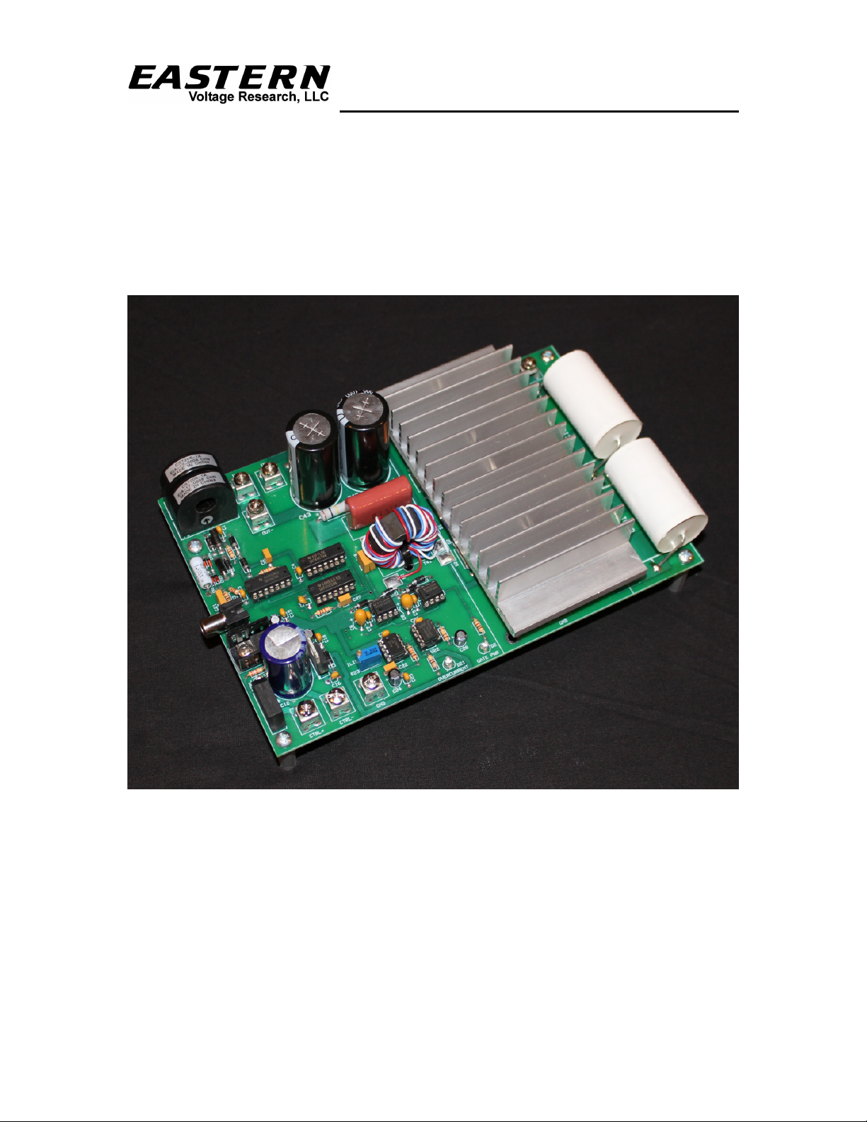
Thank you for purchasing the microBrute DRSSTC Kit. The microBrute DRSSTC is a
smaller version of our miniBrute DRSSTC system, and is our entry level DRSSTC Tesla
Coil kit. It’s a popular choice for individuals building their first disruptive based solid
state Tesla coil. The small coil produces output arcs, similar to that of a disruptive spark
gap coil, in excess of 15" and with proper tuning can achieve arc lengths approaching
20”. It also features both a self-resonant feedback circuit which tunes the coil
automatically and an active current limiting circuit which protects the solid state
switching devices from being driven with too much current. The microBrute DRSSTC is
controlled through the use of the microBrute handheld controller.
Notice to Beginners: If you are first time kit builder, you may find this instruction
manual easier to understand than expected. Each component in this kit has an individual
check box, while a detailed description of each component is provided as well. If you
follow each step in the instruction manual in order, and practice good soldering and kit
building skills, the kit is next to fail-safe.
Please read this manual in its entirety before building, testing, or operating your kit!
Circuit Description
The microBrute DRSSTC is a relatively simple second generation DRSSTC system
comprised of only a few major subcircuits. The low voltage 18VAC transformer, T2,
along with bridge rectifier, BR1, and filter capacitor, C12, provide the DC voltage
required for the Tesla coil’s control circuitry. The 7815 linear regulator, U6, provides
+15VDC which is used to provide power to the gate driver circuits, while the 7805 linear
regulator, U7, provides the +5VDC to power the control logic devices. Rectifiers, CR43
and CR44, along with capacitors, C42 and C43, provide a voltage doubling network
which convert the input 115VAC to approximately 340VDC. This 340VDC is the bus
voltage of the half-bridge switching circuit. The self-resonating drive network is
comprised of current transformer, T1, and control logic devices, U1, U2, and U3. T1
samples the primary current of the DRSSTC, and converts this current to a voltage square
wave through the clamping network consisting of CR1, VR1, CR2, and VR2. This
developed +5V square wave, which is at the resonant frequency of the Tesla Coil, is used
to drive the Tesla Coil into oscillation. The 9A gate driver ICs, U4, and U5, are driven
by this signal, and provide the +15V/-15V gate drive necessary to switch the half-bridge
switching circuit ON and OFF. Gate transformer, T41, simply provides voltage isolation
between the control circuitry and the half-bridge as the half-bridge is bouncing up and

microBrute DRSSTC Tesla Coil Kit
November 2019, Rev 5 − 11 − Copyright © 2011, Eastern Voltage Research, LLC
microBrute DRSSTC Instruction Manual
down with respect to AC neutral as it switches. To protect the half-bridge switching
devices from excessive current, it is important to sense the primary current and shutdown
the half-bridge whenever a specified current limit is exceeded. This is accomplished by
sensing current through current transformer, T21, rectifying it and comparing it to a
specified threshold through U21, a LM311 voltage comparator. When the current sample
exceeds it preset current limit threshold, it triggers an overcurrent pulse which is fed into
a synchronized shutdown circuit, comprised of U1, U2, and U3, which disables the half-
bridge switching circuit. The synchronized shutdown circuit ensures that the half-bridge
shutdowns only when it is not conducting any current. If the half-bridge shutdown while
it was conducting current, it could lead to large magnitude inductive voltage spikes which
could potentially damage the switching devices, Q41 and Q42. To control the DRSSTC,
a handheld modulator is connected via RCA connector, J1. This provides a low
frequency pulse signal which turns the DRSSTC ON and OFF at a nominal frequency of
100Hz with a very low duty cycle. The handheld modulator has two user adjustable
knobs which control both the pulse repetition frequency (PRF) and the pulsewidth. When
a modulator pulse is received at J1, the pulse first enables and turns ON gate driver, U4,
for one single pulse. This pulse provides the initial impulse necessary to start the
DRSSTC and drive it into oscillation. From that point, the primary current is then
sampled via current transformer, T1, which self-resonates the DRSSTC for the remainder
of the pulse burst where the pulse burst length is equal to the pulsewidth output of the
handheld modulator controller. The half-bridge switching circuit, comprised of high
current IGBT switching devices, Q41 and Q42, provides the +170V/-170V pulses
required to power the Tesla Coil. Finally, polypropylene capacitors, C101 and C102, in
conjunction with the Tesla Coil primary, L101, form the resonant tank circuit of the
DRSSTC. C101 and C102 make up what is commonly called the primary MMC
capacitor.
For more detailed theory on DRSSTCs, please check out our DRSSTC: Building the
Modern Day Tesla Coil book series.

microBrute DRSSTC Tesla Coil Kit
November 2019, Rev 5 − 12 − Copyright © 2011, Eastern Voltage Research, LLC
microBrute DRSSTC Instruction Manual
Kit Building Tips
A good soldering technique is key! Let your soldering iron tip gently heat both the wires
and pads simultaneously. Apply solder to the wire and the pad when the pad is hot
enough to melt the solder. The finished joint should appear like a small shiny drop of
water on paper, somewhat soaked in. If the pads have not heated up sufficiently, melted
solder (heated only by the soldering iron itself) will form a cold solder joint and will not
conduct properly. These cold joints appear as dull beads of solder, and can be easily
fixed by applying additional heat to the pad and wire. All components, unless otherwise
noted, should be mounted on the top side of the board. This is the side with the
silkscreen printing.
When installing components, the component is placed flat to the board and the leads are
bent on the backside of the board to prevent the part from falling out before soldering.
The part is then soldered securely to the board, and the remaining lead length is clipped
off. It is also extremely important to place the components as close to the board as
possible. This is necessary for proper operation over the wide frequency range of the
various kits we provide. Also be sure that component lead lengths are always as short as
possible. This will avoid adding any stray capacitances or inductances that can be
detrimental to circuit operation.
An alternative approach (which is actually the one I use) is to install the component into
the board and then apply a piece of masking tape on the topside to the hold the
component in place temporarily. The leads on the backside of the board are then trimmed
leaving about 0.10” lead protruding through the backside of the board, and then soldered
from the backside. You can then remove the masking tape, and finally apply a small
amount of solder on the top to complete the joint on both sides. This is shown in the
figure below.

microBrute DRSSTC Tesla Coil Kit
November 2019, Rev 5 − 13 − Copyright © 2011, Eastern Voltage Research, LLC
microBrute DRSSTC Instruction Manual
microBrute DRSSTC Parts List
RESISTORS
1 560 ohm Resistor (green-blue-brown), R1
1 15k Resistor (brown-green-orange), R2
3 1k Resistor (brown-black-red), R3,R5,R25
1 2.7k Resistor (red-violet-red), R4
1 1.6 ohm, 2W, Resistor (brown-blue-gold), R21
1 100 ohm Resistor (brown-black-brown), R22
1 10k Resistor (brown-black-orange), R24
1 100k Resistor (brown-black-yellow), R26
1 470 ohm Resistor (yellow-violet-brown), R27
2 5.1 ohm, 2W, Resistor (green-brown-gold), R41,R42
2 100k, 2W, Resistor (brown-black-yellow), R43,R44 (see note below)
2 10 Meg, 1/2W, Resistor (brown-black-blue), R101,R102
1 10k Potentiometer, R23
Note: 120k may be substituted for R43, R44
CAPACITORS
13 0.1uF Ceramic Capacitor, C1,C3,C4,C5,C7,C9,C13,C15,C16,C18,
C23,C25,C26 (marked 104 or BC104)
1 1000pF Ceramic Capacitor, C2 (marked 102 or BC102)
3 1uF Ceramic Capacitor, C10,C11,C21 (marked 105 or BC105)
2 10uF, 35V Tantalum Capacitor, C6,C8 (marked 106 35 or similar)
4 10uF, 50V Electrolytic Capacitor, C14,C17,C24,C28
1 2200uF or 4700uF, 35V Electrolytic Capacitor, C12
2 100pF Ceramic Capacitor, C22,C27 (marked 101 or BC101)
1 1uF, 630V Poly Capacitor, C41 (marked 105 or 125)
2 0.15uF, 2kV Poly Capacitor, C101,C102
2 1000uF, 200V Electrolytic Capacitor, C42,C43
DIODES
2 1N4002 Diode, CR9,CR10
10 1N5819 Diode , CR1,CR2,CR3,CR4,CR5,CR6,CR7,CR8,CR41,CR42
4 1N4148 Diode, CR21,CR22,CR23,CR24
2 6A8 Rectifier Diode, CR43,CR44
1 Bridge Rectifier, BR1
2 LED, Blue, D1,D2
1 LED, Red, D21
2 4.7V Zener Diode, 1N5337, VR1,VR2

microBrute DRSSTC Tesla Coil Kit
November 2019, Rev 5 − 14 − Copyright © 2011, Eastern Voltage Research, LLC
microBrute DRSSTC Instruction Manual
4 33V Zener Diode, 1N4752, VR41,VR42,VR43,VR44
2 1.5KE33CA Transient Voltage Suppressor, VR45,VR46
4 1.5KE220CA Transient Voltage Suppressor, VR47,VR48,VR49,VR50
SEMICONDUCTORS
2 IXGN60N60C2D1 IGBT, Q41,Q42
INTEGRATED CIRCUITS (ICs)
1 SN74HC14N Inverter IC, U1
1 SN74HC74N D Flip-Flop, U2
1 SN74HC08N AND Gate IC, U3
1 9A Gate Driver, Non-Inverting, UCC37322, U4
1 9A Gate Driver, Inverting, UCC37321, U5
1 15V Linear Regulator, LM7815, U6
1 5V Linear Regulator, LM7815 or LM340T5, U7
1 LM311 Voltage Comparator, U21
1 555 Timer, U22
MISCELLANEOUS
2 8DIP IC Socket (for use with U4, U5)
7 Screw Terminals
1 Power Transformer, 18VAC, 1A, T2
2 Current Transformer, T1, T21
1 Ferrite Core for Gate Transformer, T41
1 RCA Connector, J1
1 Primary Coilform (4.0” DIA)
1 Secondary Coilform (3.1” DIA)
1 Centering Ring for Primary / Secondary
2 Secondary Coil End Caps
1 Magnet Wire, 30 AWG
1 Toroid (6” x 3”)
2 Fuse Holders
1 Primary Wire, 12 AWG
1 Heatsink, Extruded Aluminum
2 Power Cords
1 Misc. Hardware
1 RCA Cable (for handheld modulator)
1 microBrute Modulator Kit
1 Heatsink, TO-220
1 Muffin Fan, 115VAC
1 Fuse, 1A, F1

microBrute DRSSTC Tesla Coil Kit
November 2019, Rev 5 − 15 − Copyright © 2011, Eastern Voltage Research, LLC
microBrute DRSSTC Instruction Manual
1 Fuse, 5A, F41
REQUIRED, NOT SUPPLIED
A/R Thermal Grease
A/R Two-Part Epoxy or similar adhesive
A/R 1” Aluminum Tape (Available at Hardware Stores)
A/R Sand Paper, Small Piece
1 Eye Protection, Safety Glasses
1 Hearing Protection
RECOMMENDED, NOT SUPPLIED
1 Enclosure for microBrute DRSSTC Board

microBrute DRSSTC Tesla Coil Kit
November 2019, Rev 5 − 16 − Copyright © 2011, Eastern Voltage Research, LLC
microBrute DRSSTC Instruction Manual
microBrute DRSSTC Component Layout Diagram

microBrute DRSSTC Tesla Coil Kit
November 2019, Rev 5 − 17 − Copyright © 2011, Eastern Voltage Research, LLC
microBrute DRSSTC Instruction Manual
KIT Building Instructions
Now we will begin building the kit. There are just a few more important things to know
before we install the first components.
For each component, the word “install” always means the following:
1. Pick the correct value to start with.
2. Insert the component into the correct printed circuit board (PCB) location.
3. Orient the component correctly – especially when there is a right and a wrong
way to solder it in. (i.e. electrolytic capacitors, diodes, ICs, transistors, etc…)
4. Solder all connections unless directed otherwise. Ensure enough heat is used to
allow solder to flow for clean, shiny, and completed connections.
Also, please be sure to take us seriously when we say that good soldering is the key to the
proper operation of your circuit!
•Use a 25W soldering pencil with a clean, sharp tip. DO NOT USE a high power
soldering gun such as those trigger activated units.
•Use only rosin core solder intended for electronics use
•Ensure your work area is clean, and has plenty of bright lighting
•Build your kit in stages, taking breaks to check your work. Be sure to clean the
board periodically with a brush or compressed air to remove any excess wire
cuttings, etc…
Okay, so lets begin!
1. Install R1, 560 ohm resistor (green-blue-brown)
2. Install R2, 15k resistor (brown-green-orange)
3. Install R3, 1k resistor (brown-black-red)
4. Install R5, 1k resistor (brown-black-red)
5. Install R25, 1k resistor (brown-black-red)
6. Install R4, 2.7k resistor (red-violet-red)
7. Install R22, 100 ohm resistor (brown-black-brown)
8. Install R24, 10k resistor (brown-black-orange)
9. Install R26, 100k resistor (brown-black-yellow)

microBrute DRSSTC Tesla Coil Kit
November 2019, Rev 5 − 18 − Copyright © 2011, Eastern Voltage Research, LLC
microBrute DRSSTC Instruction Manual
10. Install R27, 470 ohm resistor (yellow-violet-brown)
11. Install R41, 5.1 ohm, 2W resistor (green-brown-gold)
12. Install R42, 5.1 ohm, 2W resistor (green-brown-gold)
13. Install R43, 100k or 120k, 2W resistor (brown-black-yel or brown-red-yel)
14. Install R44, 100k or 120k, 2W resistor (brown-black-yel or brown-red-yel)
15. Install R101, 10Meg, 1/2W resistor (brown-black-blue)
16. Install R102, 10Meg, 1/2W resistor (brown-black-blue)
17. Install C1, 0.1uF capacitor (marking BC104 or 104)
18. Install C3, 0.1uF capacitor (marking BC104 or 104)
19. Install C4, 0.1uF capacitor (marking BC104 or 104)
20. Install C5, 0.1uF capacitor (marking BC104 or 104)
21. Install C7, 0.1uF capacitor (marking BC104 or 104)
22. Install C9, 0.1uF capacitor (marking BC104 or 104)
23. Install C13, 0.1uF capacitor (marking BC104 or 104)
24. Install C15, 0.1uF capacitor (marking BC104 or 104)
25. Install C16, 0.1uF capacitor (marking BC104 or 104)
26. Install C18, 0.1uF capacitor (marking BC104 or 104)
27. Install C23, 0.1uF capacitor (marking BC104 or 104)
28. Install C25, 0.1uF capacitor (marking BC104 or 104)
29. Install C26, 0.1uF capacitor (marking BC104 or 104)
30. Install C2, 1000pF capacitor (marking BC102 or 102 or M39014/01-1317V)
31. Install C10, 1uF capacitor (marking BC105 or 102 or M39014/02-1407 or
M39014/02-1415)

microBrute DRSSTC Tesla Coil Kit
November 2019, Rev 5 − 19 − Copyright © 2011, Eastern Voltage Research, LLC
microBrute DRSSTC Instruction Manual
32. Install C11, 1uF capacitor (marking BC105 or 105 or M39014/02-1407 or
M39014/02-1415)
33. Install C21, 1uF capacitor (marking BC105 or 105 or M39014/02-1407 or
M39014/02-1415)
34. Install C22, 100pF capacitor (marking BC101 or 101 or M39014/01-1219V)
35. Install C27, 100pF capacitor (marking BC101 or 101 or M39014/01-1219V)
36. Install C14, 10uF, 50V electrolytic capacitor. C14 has “polarity.” Polarity
means the capacitor must be inserted a certain way. You may notice that one side
of the capacitor, there is a black stripe with minus signs. This is the negative end.
Looking at the PCB silkscreen, you will notice the positive side marked. Install
this capacitor into the board ensuring the positive side of the capacitor installs in
the hole that is marked positive on the PCB layout.
37. Install C17, 10uF, 50V electrolytic capacitor. Install this capacitor into the
board ensuring the positive side of the capacitor installs in the hole that is marked
positive on the PCB layout.
38. Install C24, 10uF, 50V electrolytic capacitor. Install this capacitor into the
board ensuring the positive side of the capacitor installs in the hole that is marked
positive on the PCB layout.
39. Install C28, 10uF, 50V electrolytic capacitor. Install this capacitor into the
board ensuring the positive side of the capacitor installs in the hole that is marked
positive on the PCB layout.
40. Install C6, 10uF, 35V tantalum capacitor (marked 106 35). Install this
capacitor into the board ensuring the positive side (marked “+”) of the capacitor
installs in the hole that is marked positive on the PCB layout. The square pad is
the positive side.
41. Install C8, 10uF, 35V tantalum capacitor (marked 106 35). Install this
capacitor into the board ensuring the positive side (marked “+”) of the capacitor
installs in the hole that is marked positive on the PCB layout. The square pad is
the positive side.
42. Install CR21, 1N4148 diode. The cathode band on the diode must match that
shown on the silkscreen.

microBrute DRSSTC Tesla Coil Kit
November 2019, Rev 5 − 20 − Copyright © 2011, Eastern Voltage Research, LLC
microBrute DRSSTC Instruction Manual
43. Install CR22, 1N4148 diode. The cathode band on the diode must match that
shown on the silkscreen.
44. Install CR23, 1N4148 diode. The cathode band on the diode must match that
shown on the silkscreen.
45. Install CR24, 1N4148 diode. The cathode band on the diode must match that
shown on the silkscreen.
46. Install R21, 1.6 ohm, 2W, resistor (brown-blue-gold)
47. Install CR1, 1N5819 diode. The cathode band on the diode must match that
shown on the silkscreen.
48. Install CR2, 1N5819 diode. The cathode band on the diode must match that
shown on the silkscreen.
49. Install CR3, 1N5819 diode. The cathode band on the diode must match that
shown on the silkscreen.
50. Install CR4, 1N5819 diode. The cathode band on the diode must match that
shown on the silkscreen.
51. Install CR5, 1N5819 diode. The cathode band on the diode must match that
shown on the silkscreen.
52. Install CR6, 1N5819 diode. The cathode band on the diode must match that
shown on the silkscreen.
53. Install CR7, 1N5819 diode. The cathode band on the diode must match that
shown on the silkscreen.
54. Install CR8, 1N5819 diode. The cathode band on the diode must match that
shown on the silkscreen.
55. Install CR41, 1N5819 diode. The cathode band on the diode must match that
shown on the silkscreen.
56. Install CR42, 1N5819 diode. The cathode band on the diode must match that
shown on the silkscreen.
57. Install VR1, 1N5337 diode. The cathode band on the diode must match that
shown on the silkscreen.
Table of contents
Other Eastern Voltage Research Science Education Product manuals
Popular Science Education Product manuals by other brands

PLASTOLIGHT
PLASTOLIGHT LiteScout HBW Series User instructions

GSC
GSC LSOPT7 quick start guide

KC
KC 23.590 manual

Bresser
Bresser NATIONAL GEOGRAPHIC 9180850 operating instructions

Kyoto Kagaku
Kyoto Kagaku MW45 quick start guide

Educational Insights
Educational Insights GreenThumb Classroom Greenhouse quick start guide