®
FX: 87% black
Luminaire: 42% black
INSTALL NOTES: MO Wall Lights
Learn more about FX products. Visit fxl.com or call the techline 800-733-2823 FXLIT-188_IN_MO 10/14
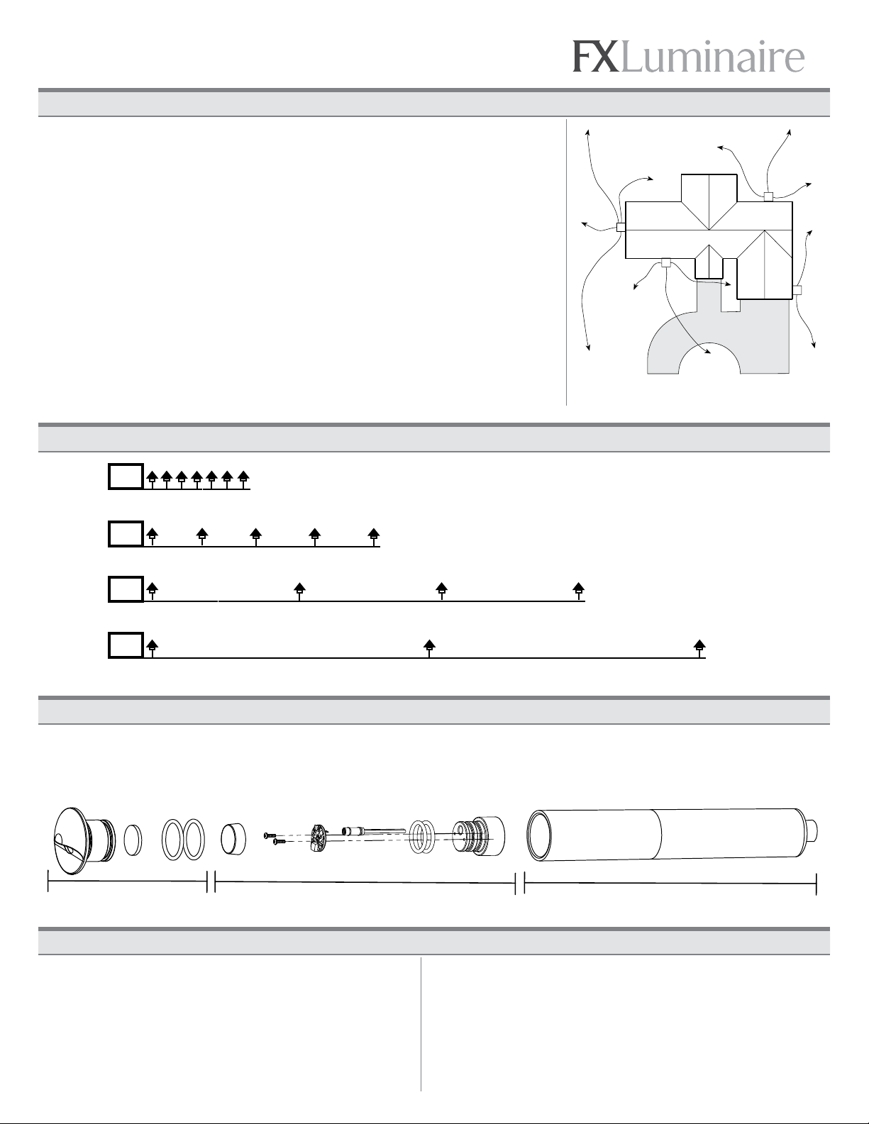
TYPICAL INSTALLATION: INSTALLATION GUIDELINES:
We have developed this series of field installation guidelines to assist you in correctly installing fixtures and transformers, ensuring
customer satisfaction and trouble-free service. If you have any questions, please call your local distributor or the FX TechLine at
800-733-2823 before proceeding. Follow all NEC guidelines and local electrical codes. For more information, visit: fxl.com
WARNING – To reduce the risk of FIRE OR INJURY TO PERSON:
• Turn off/unplug and allow to cool before replacing lamp.
• Lamp gets HOT quickly. Contact only switch/plug when turning on.
• Do not touch hot lens, guard, or enclosure.
• Keep lamp away from materials that may burn.
• Do not touch the lamp at any time. Use a soft cloth. Oil from skin may
damage lamp.
• Do not operate the luminaire fitting with a missing or damaged shield.
WARNING – Risk of Electric Shock
• Install all luminaires 10 feet (3.05 m) or more from a pool, spa, or fountain.
• A luminaire shall not use tungsten halogen lamps unless the luminaire is
marked for such lamps.
• Supply connection and electrical components are located above ground level,
except for secondary cord that is suitable for wet locations.
LOW VOLTAGE CABLE SHALL:
1. Be protected by routing in close proximity to the luminaire or fitting, or next to
a building structure such as a house or deck.
2. Not be buried except for a maximum 6 inches (15.2 cm) in order to connect to
the main low voltage cable.
3. Have the length cut off so that it is connected to a connector within 6 inches
(15.2 cm) from a building structure, a luminaire, or fitting.
AVERTISSEMENT – Pour réduire le risque D’INCENDIE OU DE BLESSURE:
• Éteignez/débranchez la lampe et laissez-la refroidir avant de la remplacer.
• La lampe devient rapidement BRÛLANTE. Ne touchez que l’interrupteur/
la prise lors de la mise sous tension.
• Ne touchez pas la lentille, le dispositif de sécurité ni le boîtier lorsqu’ils
sont chauds.
• N’approchez pas la lampe de matériaux pouvant s’enflammer.
• Ne touchez jamais la lampe. Utilisez un chiffon doux.
• La graisse de la peau peut endommager la lampe.
• N’utilisez pas le raccord du luminaire si le bouclier est absent ou endommagé.
AVERTISSEMENT – Risque d’électrocution
• Installez tous les luminaires à 3,05 m (10 pieds) ou plus d’une piscine, d’un
spa ou d’une fontaine.
• Les luminaires ne doivent pas utiliser de lampes tungstène-halogène à moins
que le luminaire soit prévu pour ce type de lampe.
• Le raccordement au réseau électrique et les différents matériels électriques
doivent installés au-dessus du niveau du sol, exception faite pour les fils ou
réseaux secondaires qui conviennent aux lieux humides
LE CÂBLE BASSE TENSION DEVRA:
1. Être protégé en le faisant passer à proximité du luminaire ou du raccord,
ou à côté d’une construction comme une maison ou une terrasse.
2. Ne pas être enterré sauf à un maximum de 15,2 cm (6 pouces) pour être
branché au câble basse tension principal.
3. Être raccourci de manière à être branché à un connecteur situé à moins de
15,2 cm (6 pouces) d’une construction, d’un luminaire ou d’un raccord.
SAVE THESE INSTRUCTIONS: CONSERVEZ SOIGNEUSEMENT CES INSTRUCTIONS:
DO NOT EXCEED 15 VOLTS IN THIS FIXTURE
The LEDs in this product function ideally when the incoming voltage is between
10–15 volts. Voltages outside of this range may damage the LEDs, shorten their
life, and cause unsatisfactory performance. The use of improper voltage voids
the product warranty. Use only a UL 1838 approved power supply.
Low Voltage
Landscape Lighting
3YJ8
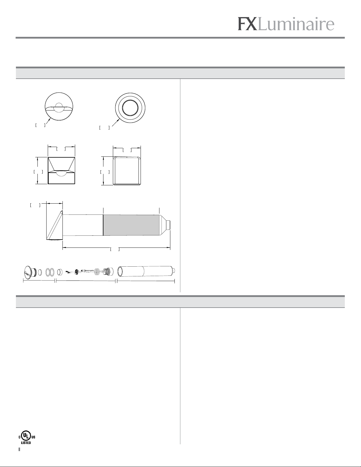
MO–RD:
MO–SQ:
MO–ST:
MO–WW:
MO–WW (Side View)
MO–RD (Exploded View)
Ø3.25 in.
82.55 cm
Ø 3.25 in.
82.55 cm
3.25 in.
82.55 cm
3.33 in.
84.71 cm
1.80 in.
45.74 cm
12.00 in.
304.8 cm
Do not cut to size within shaded region
3.25 in.
82.55 cm
3.25 in.
82.55 cm .97
24.57
12.00
304.8
3.25 in.
82.55 cm
3.33 in.
84.71 cm
1.80 in.
45.74 cm
12.00 in.
304.8 cm
Do not cut to size within shaded region
The MO is a faceplate-adjustable LED Wall Light. Each of the three
components (faceplate assembly, LED module, and conduit sleeve)
must be included into every installation to achieve proper functionality.
Faceplates are intended for vertical installation:
RD & SQ – Down light only, mounted on a vertical surface.
ST & WW – Mounted in any orientation on a vertical surface.
The ST and WW faceplates may be installed on horizontal surfaces only
in covered areas where water cannot access the fixture or pool.
A 2" schedule 40 conduit is included in a length of 12 inches. This
conduit can be cut to length, but must always fully capture the fixture
base. Due to the tapered design, do not cut past the line indicated on
the conduit. Thus, the included conduit cannot be cut any shorter than
7–1/2". If a shorter length is required, a standard 2" conduit is required.
Insert the MO LED module into the faceplate, and then press the
complete assembly into the installed conduit. The module and
faceplate must be fully pressed together to maintain proper seal.
Ensure the faceplate is pressed as flush as possible to the mounting
surface.
To change color temperature, insert a colored filter into the faceplate
as shown on the exploded view drawing. Only one filter can be used at
a time.
The LED board in this product is designed to offer years of use without replacement.
Should you need to replace the LED board, please contact your local FX
distributor for a board replacement and the necessary instructions.
LED module
Faceplate
Conduit Sleeve