5. Operation
Page 5
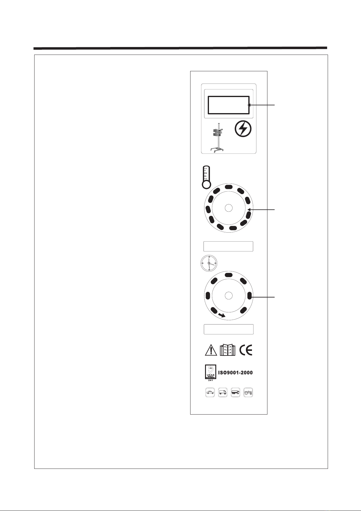
Data displayed on screen
Connect input power Switch on
ON
OFF
Switch off
ON
OFF
30-60cm
Keep heat source parallel
to paint surface at a
distance of 30-60cm
2
1. Connection of electrical supply. Make sure that the supply cable is at least 4mm at 220V.
Note: Make sure that the facility supply voltage and frequency are the same as shown on
the equipment name plate.
2. Connect to AC 220V power supply. Switch on the equipment. The LED display will show
the normal voltage as 220V.
3. Set time and power according to the requirements of the paint material to achieve the
best curing result. (Usually, the values are set to 15mins and 70% in power.)
4. Adjust the distance from the heat source to paint surface. (Usually, keeping the distance
of 45cm from the paint surface is best.)
5. Protect the lamp against shocks and vibrations especially when it is cold.
6. During the curing process, the paint surface must be clean, without water and impurities.
7. Preferably do not touch the quartz with bare hands. If grease or chemical compounds
have been deposited on the quartz, simply clean with a cloth moistened with alcohol.
Set up temperature Set up time
00
10
20
30
40
50
60
ON
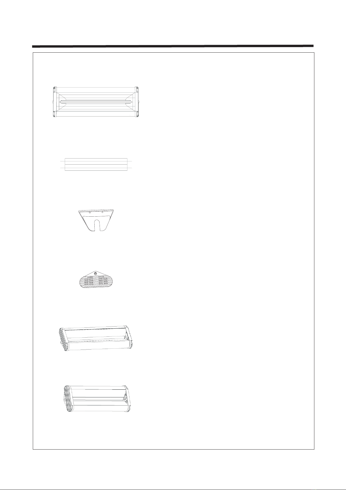
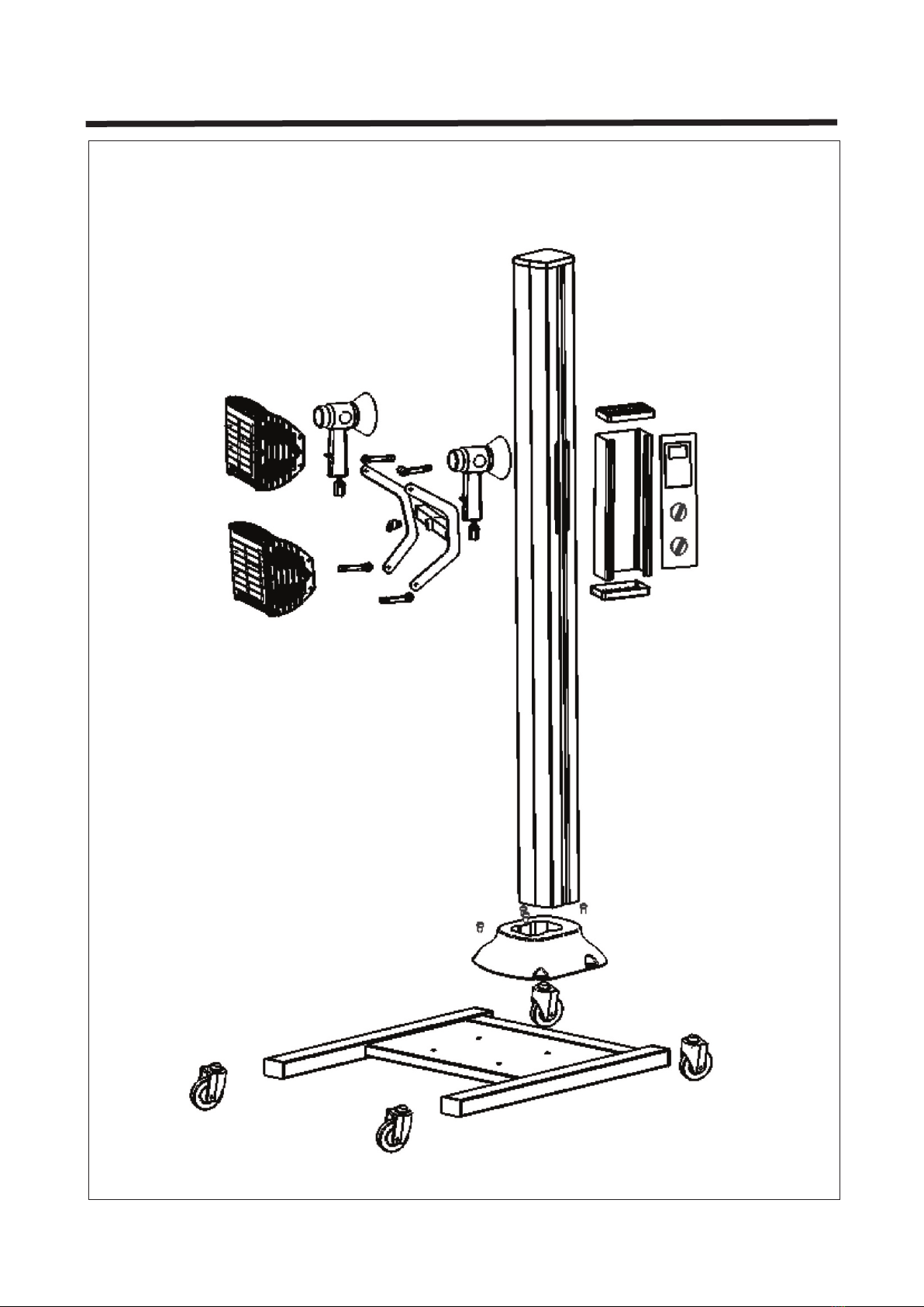
Install machine