Fytech FY-3DH User manual

Instruction Manual
FY-3DH
Our equipment is approved by the following car manufacturers (China)

Contents
1. Precautions
2. Specifications
3. Installation
4. Controls
5. Operation
6. Troubleshooting
1) Troubleshooting
2) Lamp Tube Replacement
7. Exploded View
8. Circuit Diagram
1
2
3
4
5
7
8
9
10

Page 1
1. PRECAUTION
1. Read this manual carefully before installing or using this equipment.
2. This equipment is designed for paint drying applications. Adjust to the correct
temperature and check minimum safe distance from the heat source when using.
Improper use may cause paint surface damage.
3. Installation and servicing must be performed by a qualified installer or service agency.
4. The system has been designed for easy installation, low operating costs and minimal
maintenance. The warranty does not cover lamp tube defects resulting from misuse or
improper operation.
5. Disconnect power source when the equipment is not in use for a long time.
6. The light tube should not be perpendicular to the ground when the equipment is in
operation. Otherwise, it will shorten the useful life of the light tube.
7. Make sure the cassette plug is tightly connected before using to prevent it from burning.

Model
Input Voltage
Input Power
Curing Area
Temperature
Time Setting
Light Intensity
FY-3DH
220V / 1-ph / 50-60Hz
3 × 1000W
1200 × 1000mm
35°C - 80°C
0min - 99mins adjustable
10% - 100%
2. SPECIFICATIONS
Page 2

3. INSTALLATION
Page 3
The shortwave infrared curing lamp is divided into 3 parts (a base, a column and a cassette).
1) Installation of the base.
a. Open the packing of the base.
b. Install the four wheels on the base respectively and tighten up the screws. Usually, the
wheels with brakes should be mounted on the rear of the base.
2) Installation of the column.
a. Open the packing of the column.
b. Put the column vertically on the top of the base, directly engage the screw holes and
tighten up using the screws.
c. Connect the support arm with the column for supporting cassette.
d. Connect the lifter with the column to control the up and down movement of cassette.
3) Installation of the cassette.
a. Open the packing of the cassette.
b. Connect cassette with support arm and tighten up with the screws.
c. Connect control wires and adjust the angle of cassette.
2
1
4
3
5
6
7
8
9
1. Cassette
2. Connecting rod
3. Lifter
4. Control box
5. Lifter handle
6. Column
7. Wheel
8. Base
9. Sensors

Pull-up this handle
for cassette moving
up and down.
Pull-up this handle
for cassette moving
up and down.
Pull-up this handle
for cassette moving
up and down.
Pull-up this handle
for cassette moving
up and down.
Pull-up this handle
for cassette moving
up and down.
Pull-up this handle
for cassette moving
up and down.
3 s
①
②
③
AUT O
1
2
3
5
6
7
8
4
3
1. LCD display
2. Lamp selector (each lamp can be controlled
separately)
3. Power adjustment
4. Time adjustment
5. Setting:
- Press the button once, it will enter into
"Routine" mode when the lamp is on.
- Press again, it will enter into "Pulse" mode
when the lamp is on.
- Press and hold to enter into curing
parameters setting mode.
6. Auto mode
7. Start
8. Stop
4. CONTROLS
Page 4
1. Setting for Distance
Press and hold the "Setting" (Button 5) to enter into setting mode. Set the curing parameters
according to the requirements of different paints. Nearest distance: The equipment will stop
automatically when the distance between the panel and emitter is less than its preset distance.
Farthest distance: The equipment will stop automatically when the distance between the panel
and emitter exceed its preset distance. The equipment works only in the preset distance range.
2. Setting for Temperature
Press "Power adjustment" (Button 3) when the lamp is ready to use to set the temperature.
3. Setting for Automatic Mode
Press "Setting" (Button 5) when the lamp is ready to use to set curing parameters (shown on
LCD display) according to the requirements of different paints to achieve the best effect - see
next page.

5. OPERATION
Page 5
1. Automatic Mode
a. Properly assemble the curing system according to the instruction (see page 3).
b. Switch on the power supply. The system is ready to use when the graphic appears on the
display screen as follows:
00:00
POWER:80%
00CM
00℃
Routine
Pulse
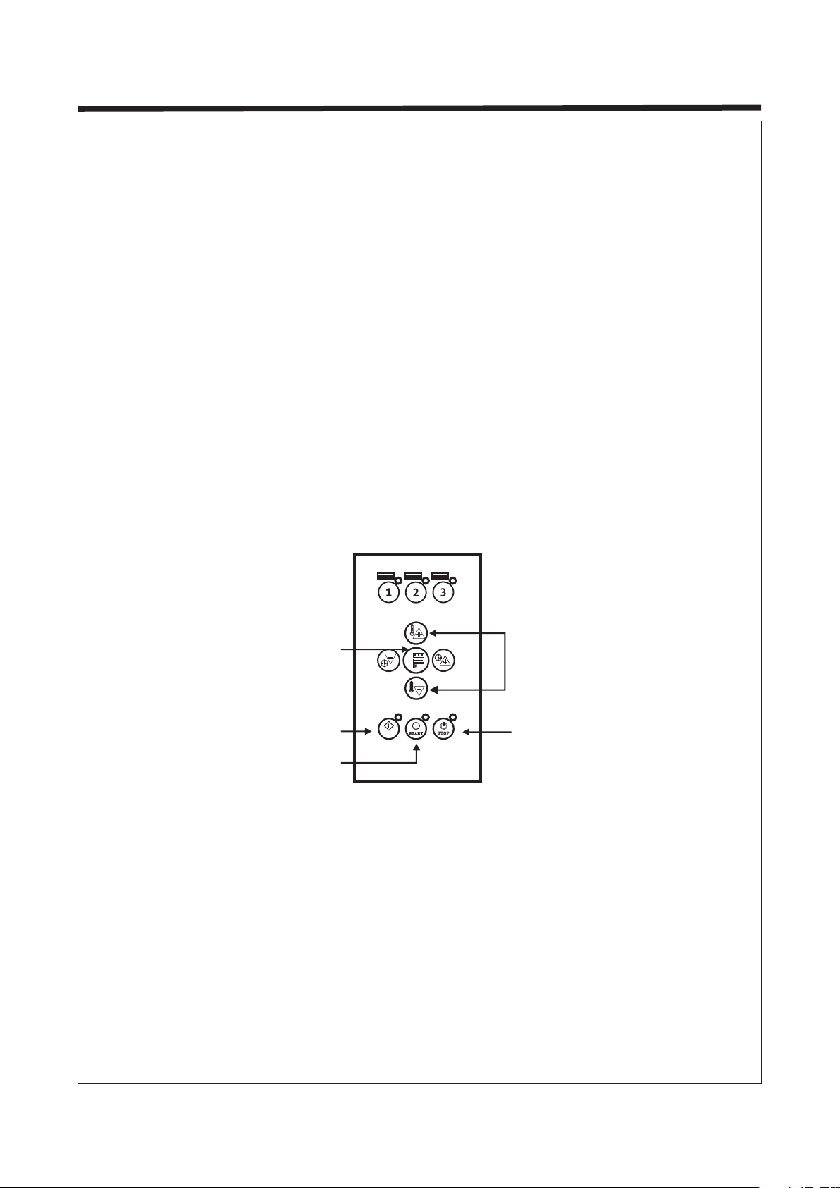
e. Setting curing time. Press the navigation buttons "time +" or "time -” (Button 4, Page 4)
when the lamp is ready to use to adjust curing time.
f. Protect the lamp against shocks and vibrations when the lamp is in use.
g. After this program is completed, the system is able to carry out other programs. Make
sure to turn off the system when the equipment is not in use and keep the equipment
securely in place.
step1
step2
step3
step4
⸠ (5min)Routine Time
Power(70%)
Pulse Time(15min)
Power(60%)
Routine Time(5min)
Power(60%)
Pulse Time(15min)
Power(60%)
1.Nearest distance (20cm)
2.Farthest distance (70cm)
3.Lowest Temperature (35°C)
4.Highest Temperature (75°C)
d. Press the "Auto" button and then press "Start" to go into the automatic curing mode.
Once the automatic mode is selected, four related cure programs become available to
the user – Program 1-4 . (The curing time and power should be set according
to the requirements of the paint material).
d. The time and power can not be set directly
during the program running.
1.The data can be set before the program started.
2.The data can also be adjusted during program
with a long press on the button “Setting”
changing the interface to set the data.
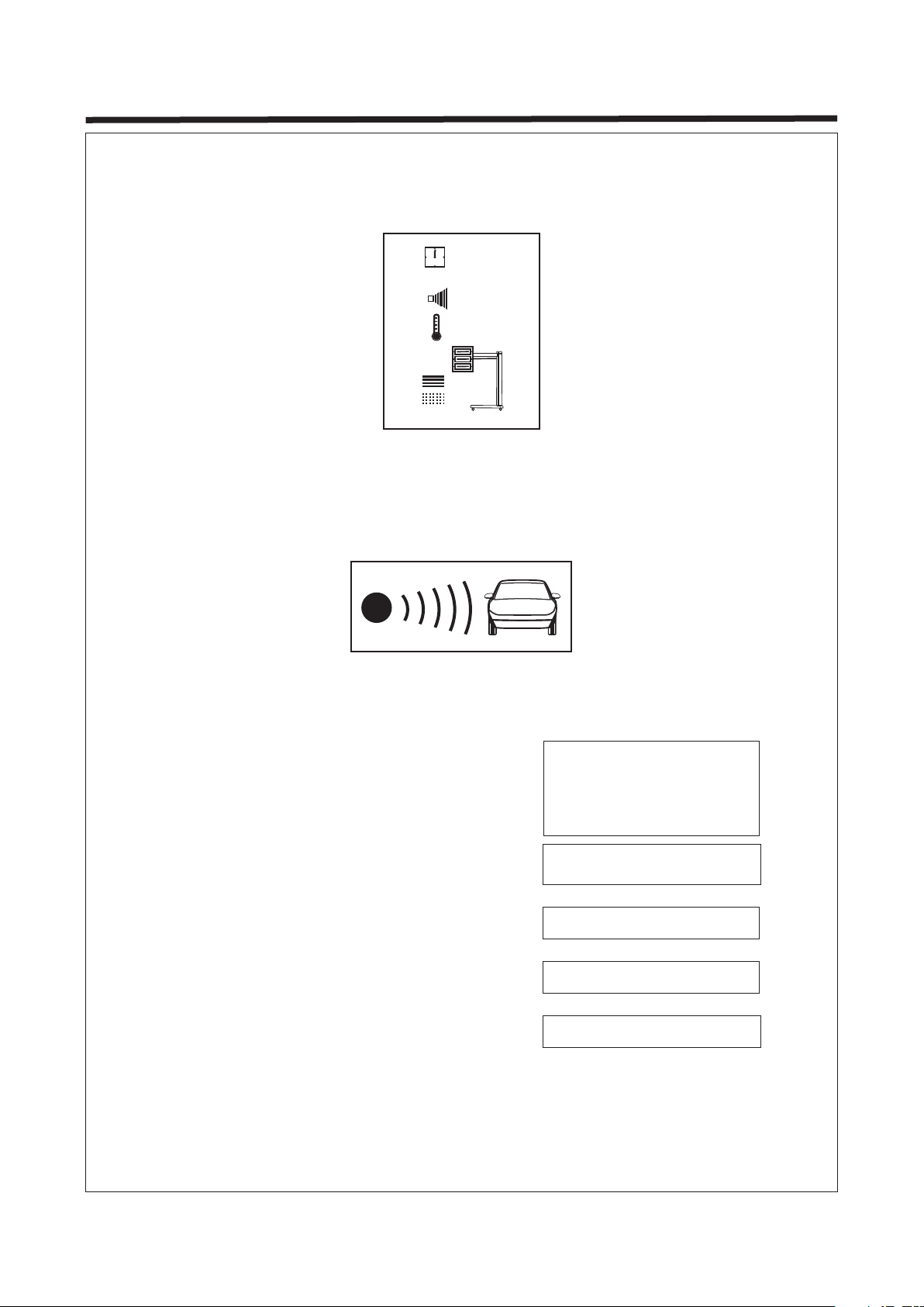
c. Move the cassette forward or backward from the paint surface to adjust to the best
distance for curing. The distance data will be detected and shown on the display screen
automatically. The measuring range is 20-120cm and beyond it is blind zone. The curing
distance between the cassette and paint surface should be set according to the paint
material and weather conditions (air humidity). Usually, keeping a distance of about
45cm from the paint surface is recommended.

5. OPERATION
Page 6
3 s
①
②
③
AUT O
Setting
Power Adjustment
Start
Auto Stop
2. Manual Mode
a. Press the navigation buttons "Power +/- " and "Time +/-" when the lamp is ready to use
to adjust the curing power and time.
b. Press the button "Setting" to set the mode of "Routine" or "Pulse”.
c. Press the button "Start".
d. The curing distance between the cassette and paint surface should be set according to
the paint material and weather(air humidity). Usually, keeping a distance of about 45cm
from the paint surface is recommended.
e. The curing time and power should be set according to the requirements of the paint
material. Usually, "Pulse" is set to 5 mins and "Routine" to 10 mins.
g. Turn off the equipment when the work is completed.
3. Pulse Mode
a. Set power and time. Press the button "Setting" and select "Pulse".
b. Press the "Start" button.
c. The curing distance between the cassette and paint surface should be set according to
the paint material and weather (air humidity). Usually, keeping a distance of about 45cm
from the paint surface is recommended.
d. After this program is completed, the system is able to carry out other programs. Make
sure to turn off the system when the equipment is not in use.

1. Troubleshooting
Page 7
6. TROUBLESHOOTING
PROBLEM
Lamp tube does not work
Lamp tube does not turn
off
Digital display is blank or
is incomplete
Temperature and time
cannot be adjusted
CAUSE
a. Lamp tube damaged
b. Lamp is not plugged in
c. Control silicon damaged
a. Control silicon damaged
a. Unplugged flat wire in
circuit board
b. Digital display damaged
a. Switch imbalance
b. Keyboard has exclusion
SOLUTION
a. Check lamp tube
b. Plug in lamp holder
c. Check control silicon
a. Check control silicon
a. Check flat wire
b. Check digital display
a. Check the installation
of switch
b. Check keyboard exclusion

2. Lamp Tube Replacement
(a)
(b)
(c)
(d)
(e)
(f)
a. Prepare cassette for replacement.
b. Remove the grille of cassette.
c. Remove the plates from both ends
of the cassette.
d. Remove the fixed plates from both
ends of the cassette.
e. Loosen fixed screws and cut off
connections, the lamp can be
replaced.
f. Repeat the steps above in reverse
order to replace the lamp.
6. TROUBLESHOOTING
Page 8

Page 9
NO
1
2
3
4
5
6
NO
7
8
9
10
11
12
NO
13
14
15
16
17
18
NO
19
20
21
NAME
Column
Top cover
Plastic band
Upper connecting rod
Connector
Adjustable hand wheel
NAME
Aluminium handle
Clamping bar
Side panel
Cassette
Plastic handle
Lower connecting rod
NAME
Lifter
Front wheel
U-type base
Back wheel
Cover plate (lower)
Handle
NAME
Cover plate (upper)
Circuit board
Sensor box
1
2
3456
11
12
13
14
15
16
17
18
19
20
7
8
9
10
21
7. EXPLODED VIEW

12345
PCB1
Distance sensor
PCB2
Temperature sensor
Control
Transformer
Main
switch
20
19
18
17
16
20
19
18
17
16
32
31
30
CND
GON
+DC12V
A1A2
Ba1B2
C1C2
Page 10
8. CIRCUIT DIAGRAM
Table of contents
Popular Outdoor Light manuals by other brands

Dale Tiffany
Dale Tiffany TT60574 Assembly instructions

HUDSON VALLEY LIGHTING
HUDSON VALLEY LIGHTING WES installation instructions

MOOD
MOOD COGOLIN Installation and operating instructions

Renson
Renson Linarte manual

OmniFlow
OmniFlow OMNILED 07 owner's manual

Home Decorators Collection
Home Decorators Collection JL0905-H Use and care guide

Eaton
Eaton HALO MS276RD instruction manual

Brinkmann
Brinkmann Solar Gallery Stainless Steel Tier owner's manual

Luminar Outdoor
Luminar Outdoor 59268 owner's manual

SLV Elektronik
SLV Elektronik SITRA 360 SPIKE operating manual

Lumirama
Lumirama DEL TIME installation guide

LIGMAN
LIGMAN QUANTUM 1 installation manual