manuals.online logo
Brands
  1. Home
  2. •
  3. Brands
  4. •
  5. G3
  6. •
  7. Fitness Equipment
  8. •
  9. G3 Onyx User manual

G3 Onyx User manual

©2009 G3 Genuine Guide Gear Inc. 0901217 Rev C
Mounting and Installation Instructions
1 3 4
2
x10 x4 x4
x8
5
x2
6
x4
8
x2
9
x2
7
x2
11 x2
10 x2
12 x2
1:1
1:1
1. Toe Mounting Screw
2. Heel Mounting Screw
3. Toe Positioning Screw
4. Heel Cowling Screw
5. Toe Mounting Plate
6. Toe Mounting Plate Insert
7. Toe Assembly
8. Heel Mounting Plate
9. Length Adjustment Plate
10. Heel Assembly
11. Front Cowling
12. Leash Clip
13. G3 Spacer Tool
13 x1
1. Notes
•The installation of the binding should only be
performed by an authorized G3 dealer
The G3 Onyx binding is compatible only with
alpine touring ski-boots (ISO 9523) with TECH
compatible inserts
•Bellowed touring boots, such as the Scarpa® F1, F3
and Terminator X series boots, can only be used with
the Onyx boot shim installed. The shim is available as
an accessory item from G3.
Warning: Using a bellowed boot with the G3 Onyx
binding will affect the safety release of the boot
from the binding. G3 cannot guarantee the
release settings of the binding when used with
these boots. Refer to the instructions included
with the Onyx boot shim for further details.
2. Mounting and Installation
•Inspect the ski and binding for any visual signs of
damage or wear. Replace any worn or damaged parts.
2.1. Mounting
•Always follow the ski manufacturer’s recommendation
for binding mounting location to ensure that the
binding is mounted in the correct binding mounting
area on the ski.
•The G3 Onyx binding mounting pattern is compatible
with Dynafit® binding patterns. Use a G3 Onyx
mounting jig, or Dynafit® compatible jig to locate and
drill holes in the ski.
•The G3 Onyx is designed to mount to skis with drilled
hole sizes from ø3.5mm to ø4.1mm x 9mm. For skis
with a metal topsheets, use a tap and follow the ski
manufacturer’s recommendation for ideal drill size.
•Set the jig to the boot sole size either by fitting the
boot to the jig, or by setting the jig length to match the
desired sole length. Table 3, “ONYX Mounting Guide,”
at the end of this document can be used to determine
the sole length range available for adjustment given a
chosen mount size set by the jig.
•Place the jig on the ski and align the center mark of
the jig to the center mark of the ski. If the ski does not
have a center mark, either:
a) use the ski manufacturer’s recommended
measurement to locate the center mark
b) locate the cord center of the ski and mark it. Align
the jig such that boot toe is aligned to this mark.
•Fix the jig in place and drill the holes using the
recommended drill size; either ø3.5 mm x 9 mm or
ø4.1 mm x 9 mm. (4.1 mm for skis with metal
topsheet)
•Remove chips or dust from the holes. Holes should be
glued with waterproof glue and/or tapped if
recommended by the ski manufacturer.
2.2. Installation of Mounting Plates
•NOTE: Always use G3 Onyx mounting screws
supplied with the binding. If the screws have
©2009 G3 Genuine Guide Gear Inc. 0901217 Rev C
become stripped or damaged, replace only with G3
Onyx mounting screws. Using incompatible screws
will likely result in damage to the binding or ski, and
possible separation of the binding from the ski.
•Ensure the toe mounting plate inserts (6) are installed
in the toe mounting plate before the plate is mounted
to the ski
•Place the toe mounting plate (5) on the ski as shown.
Ensure the mounting plate is aligned properly to the
mid line of the ski and is flush to the ski top sheet.
Install the five toe mounting screws (1) and torque to
4 Nm using a #3 Pozidrive driver.
•Ensure the length adjustment plate (9) is installed in
the heel mounting plate before the plate is mounted to
the ski.
•Mount the heel mounting plate (8) on the ski as
shown. Install the four heel mounting screws (2).
Ensure the heel plate sits flush on the ski top sheet.
Check that the metal length adjustment plate is
installed against the ski. Torque the mounting screws
to 4 Nm using a #3 Pozidrive driver.
2.3. Installation of the Leash Attachment Clip
•NOTE The ski leash clip should be installed on any
binding that does not have a ski brake installed.
•The toe piece must be off the ski to be able to install
the clip.
•The leash clip can be installed on either the left or right
side of the toe piece.
•Insert ends of the clip (12) into the holes on the
underside of the toe piece.
•Fold the clip flush with the underside of the binding.
2.4. Toe Installation
•Slide the toe assembly (7) backwards onto the toe
mounting plate (5) from the front/tip end of the toe
mounting plate, and align the back edge of the toe
assembly with the 0 mm mark on the mounting plate.
•Install the two toe positioning screws (3) using a #3
Pozidrive screwdriver and torque to 5.6 Nm. Note: the
toe position can be moved in two 7.5mm increments
to adjust the boot position on the ski and
accommodate larger or smaller boot sizes.
2.5. Heel Installation
WARNING: Heel installations and removals from
the base plates must be performed with the
lateral release setting set to its minimum. Failure
to do this could result in damage to the binding.
•Slide the heel assembly (10) forwards onto the heel
mounting plate (8) from the rear/tail end of the heel
mounting plate until it makes contact with the length
adjustment plate (9) and is approximately in the
position shown.
•While pushing slightly
forward on the heel and
turning the length
adjustment screw clockwise
with a #3 Pozidrive
screwdriver, adjust the
position of the heel until it is
approximately in the centre
of it’s adjustment range, as
shown by the position
indicator.
•If you are not installing the Onyx Ski Brake; install the
front cowling (11) by sliding it on from the front/tip of
the heel mounting plate (8) and installing the heel
cowling screws (4) into the heel with either a #1
phillips or a #1 Pozidrive screwdriver and torque them
to 1.1 Nm.
•If you are installing the Onyx Ski Brake, refer to the
installations instructions included with the brake.
2.6. Heel Location Setting
WARNING: Binding performance is sensitive to
the heel location being set accurately. Too large
a gap could result in the binding releasing too
easily; too small a gap will affect release values
and can cause interference between the boot
and binding while touring. It is very important to
have a 6mm gap between the boot heel and the
binding after installation.
•Install a ski boot into the binding with the heel
positioned in ski mode.
•Use the supplied 6mm G3 spacer tool (13) to set the
gap between the binding and boot. The shim should fit
snugly between the binding and the boot. Use a #3
Pozidrive screwdriver to adjust the boot length
adjustment screw Note: Do not over tighten the
boot length adjustment screw.
©2009 G3 Genuine Guide Gear Inc. 0901217 Rev C
3. Release Value Adjustment
•The G3 Onyx binding has two release modes:
lateral twisting (Mz), and forward falling (My). Your G3
ONYX binding has a lateral twist (Mz) release setting
scale from 6-12, and a forward falling (My) release
setting scale from 5-10. Please choose an appropriate
value using the selection of release values chart
provided in the following section (In accordance with
ISO 11088/ ASTM F939).
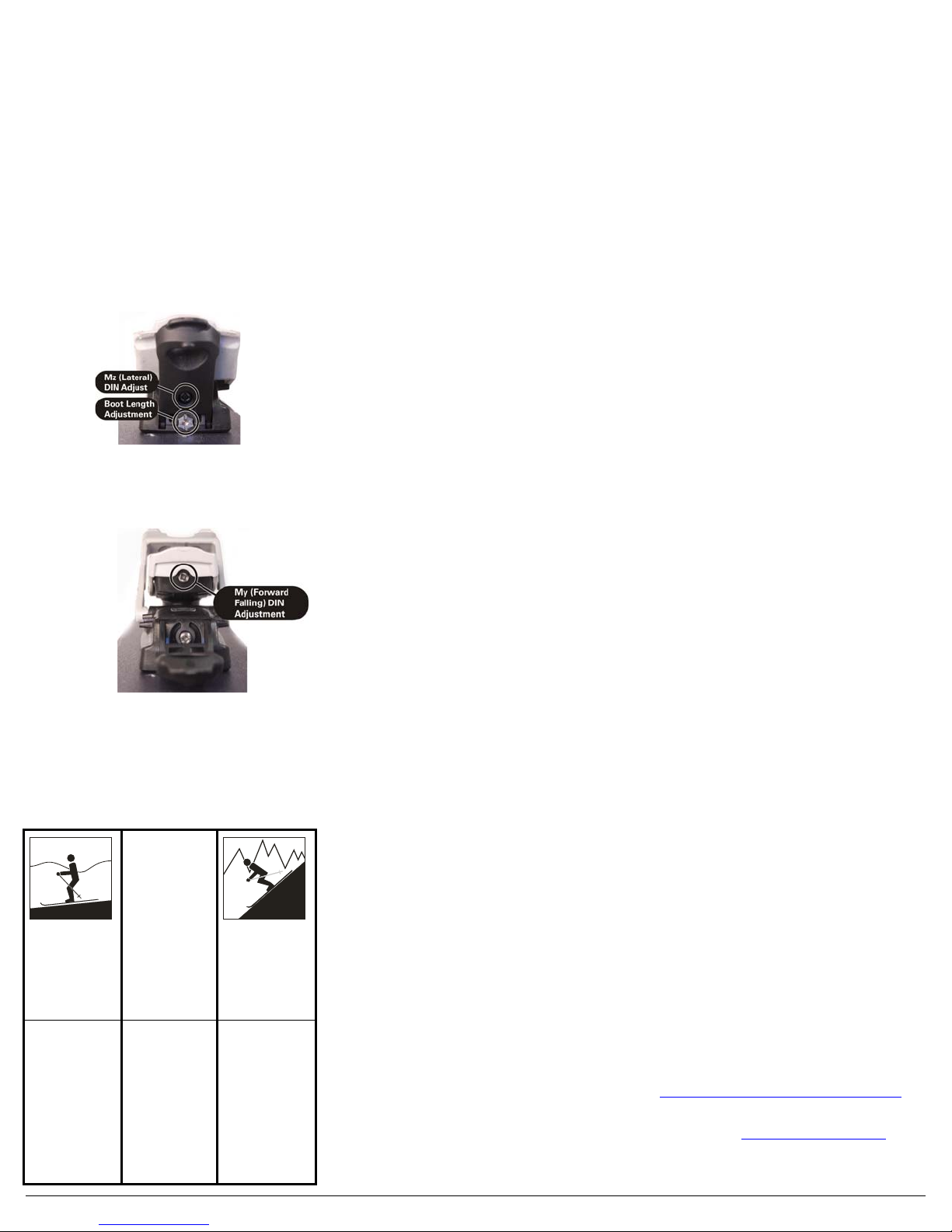
3.1. Setting of Lateral (Mz) Release
•NOTE The heel tour mode lever must be in ski
mode in order to set Mz release.
•Mz(twisting) DIN adjustment is located on the main
heel body, above the boot length adjustment screw.
Using a Pozidrive #3 screwdriver, turn adjuster clock-
wise to increase release setting, and counter clock-
wise to decrease setting.
3.2. Setting of Forward Falling (My) Release
•My (forward falling) DIN adjustment is located on the
upper part of the heel. Using a Pozidrive #3, turn
adjuster clock-wise to increase release setting, and
counter clock-wise to decrease setting.
4. Selection of Release Setting Values
(ISO 11088/ ASTM F939)
4.1. Determination of Skier Type
•It is the responsibility of the skier to determine his/her
skier-type classification as defined in Table 1
Table 1 – Determination of Skier-type
Classification
Skiers that do
not meet the
descriptions of
either
1 or 3
Type 1 Type 2 Type 3
Cautious skiing on
smooth slopes of
gentle to moderate
pitch
Fast skiing on
slopes of moderate
to steep pitch.
Skiers who designate
themselves as Type 1
receive lower than
average release settings.
This corresponds to an
increased risk of
inadvertent binding
release in a fall.
This type also applies to
entry level skiers
uncertain of their skill
level.
Skiers who designate
themselves as Type 2
receive average release
settings appropriate for
most recreational skiing.
Skiers who designate
themselves as Type 3
receive higher than
average release settings.
This corresponds to
decreased capacity for
release in a fall, in order
to gain a decreased risk
of inadvertent binding
release.
•Skiers 10 years of age or older of any type who desire
a higher or lower setting than the setting of their skier
type according to Table 1, may do so in the following
cases:
•Skiers who have satisfactory experience with lower
settings regarding these recommend-dations may
request setting based on their experience.
•Skiers who have satisfactory experience without
inadvertent releases may request a setting up to 15%
lower than that recommended in Table 2
•Skiers having certain characteristics, such as neutral
skiing technique, defensive attitude, high degree of
control, etc. may request a setting of 15% lower than
that recommended in Table 2.
•Skiers who have experienced inadvertent releases
may request a setting up to 15% higher than that
recommended in Table 2.
•Skiers may request settings that are different for
lateral twist and forward lean.
•If a skier selects a different skier type for forward lean,
record the choice with a (/) separating the two types,
in the order lateral twist/forward lean (LT/FL)
•If a skier selects discretionary settings lower than
those derived from Type 1, record this selection with a
(-) symbol. For example Type 1-
•If a skier selects discretionary settings higher than
those derived from Type 3, record this selection with a
(+) symbol. For example Type 3+
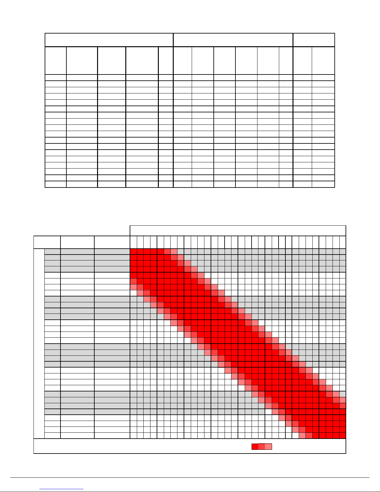
4.2. Selection of Release Settings
•Locate the skier’s weight (mass) and height in the
appropriate column in Table 2. If weight and height are
not on the same line, select the line closest to the top
of the table.
•Adjustment for skier type (see 4.1):
For a Type 1 skier, stay on the line and use that
skier code.
For a Type 2 skier, move down the table one skier
code.
For a Type 3 skier, move down the table two skier
codes.
If the skier is age 9 and younger, or 50 and older,
move up the table one skier code.
•If separate lateral twist (Mz) and forward lean (My) skier
types were selected, repeat the selection of release
settings above for the second skier type, recored the
resulting codes in the order LT/FL.
4.3. Release Value Determination
•Locate the release value at the intersection of the
skier code row and the appropriate boot sole length. If
there is a blank box, move left or right to the in same
row to the next value.
•Note that release values selected using this
practice may not be appropriate for circumstances
in which:
the skier carries an object that significantly
increases the skier’s effective body weight,
the skier grasps or in some manner controls an
object such as a sled, or the skier encounters
exceptional snow or terrain
conditions not commonly found on developed ski
slopes.
•Release torque values outside the recommendations
of this practice may increase the risk of injury to the
skier. However, skiers who are informed of this
potential risk may request such settings and have
them provided, subject to the guidelines and
limitations specified in this document.
•These values refer to recommended release torque for
initial adjustment of a ski binding and subsequent
readjustment of the binding during routine
maintenance or following a suspected malfunction.
However, these values are not intended to apply to
the condition of the equipment at any time after it is
put into use.
5. Checks and Functional Tests
•Upon completing installation and setting of the
binding, the following inspection and functional checks
should be performed:
•boot center mark is aligned with the ski center mark
•toe piece with the heel piece alignment by installing a
boot in the binding, and checking that the binding heel
pins are aligned with the boot insert.
•heel location by checking gap between boot and
binding.
•both lateral twisting (Mz), and forward falling (My)
adjustments on both bindings are set to the correct
value.
•lateral release travel by hitting the heel of the boot to
displace it several mm and ensure that the binding
returns to center quickly and smoothly.
•heel pins do not interfere with the boot when the
binding is in tour mode, and that the heel can easily be
engaged and disengaged from tour mode.
•toe positioning screws are tightened to the correct
torque
•verify release values with a binding test device. Follow
the manufacturer’s instructions for Dynafit®
compatible bindings.
6. Troubleshooting
•If the lateral release (Mz) is not symmetrical, check the
following:
worn boot inserts
toe piece alignment with the heel. Check by
installing boot in toe and checking that binding heel
pins are aligned with boot heel insert. Test with
multiple boots to ensure that boot heel and toe
inserts are correctly aligned in boot.
dirt contamination or excessive wear of binding
components, in particular the toe pins or heel pins.
heel location by checking gap between boot and
binding. Refer to section 2.6.
7. Instructions to Customer
•Explain the operation and features of the binding. In
particular:
Switch from ski to tour mode
Correct operation of heel lifts
Use of toe tour mode lock
•Explain the importance of regular maintenance and
performance checks. The binding should be kept free
of dirt and other contamination and that at the
beginning of each season, and/or after 60days of
skiing, G3 Onyx bindings be checked by an authorized
G3 dealer and have the release setting recalibrated
•Explain that the binding release values are set to the
customers personalized settings. Tell the customer
the setting values selected, and where the setting
adjustments are located.
•Explain the importance of having the binding adjusted
correctly for boot sole length.
•Provide the customer with the retail box and include all
instruction manuals.
•If the customer experiences any problems or issues
with the boot, binding or ski, they should contact an
authorized G3 dealer.
8. Warranty
•For complete warranty information, please visit:
http://www.genuineguidegear.com/service/g3-product-warranty
9. Additional Information
•The G3 website www.genuineguidegear.com has the
most current information regarding all G3 products.
Please go to the website to find any recent updates
and additional information on how to use the product.
©2009 G3 Genuine Guide Gear Inc. 0901217 Rev C
Table 2 – Release Value Selection Using Skier’s Weight
Table 3 - ONYX Mounting Guide
Fit Range
1
Fit Range when using
a Dynafit® Brand
MountingJig
1
270
273
275
278
280
283
285
288
290
293
295
298
300
303
305
308
310
313
315
318
320
323
325
328
330
333
335
338
340
343
345
348
270
254mm-287mm
253mm-283mm
273
256mm-289mm
255mm-285mm
275
259mm-292mm
258mm-288mm
278
261mm-294mm
260mm-290mm
280
264mm-297mm
263mm-293mm
283
266mm-299mm
265mm-295mm
285
269mm-302mm
268mm-298mm
288
271mm-304mm
270mm-300mm
290
274mm-307mm
273mm-303mm
293
276mm-309mm
275mm-305mm
295
279mm-312mm
278mm-308mm
298
281mm-314mm
280mm-310mm
300
284mm-317mm
283mm-313mm
303
286mm-319mm
285mm-315mm
305
289mm-322mm
288mm-318mm
308
291mm-324mm
290mm-320mm
310
294mm-327mm
293mm-323mm
313
296mm-329mm
295mm-325mm
315
299mm-332mm
298mm-328mm
318
301mm-334mm
300mm-330mm
320
304mm-337mm
303mm-333mm
323
306mm-339mm
305mm-335mm
325
309mm-342mm
308mm-338mm
328
311mm-344mm
310mm-340mm
330
314mm-347mm
313mm-343mm
333
316mm-349mm
315mm-345mm
335
319mm-352mm
318mm-348mm
338
321mm-354mm
320mm-350mm
340
324mm-357mm
323mm-353mm
343
326mm-359mm
325mm-355mm
345
329mm-362mm
328mm-358mm
348
331mm-364mm
330mm-360mm
2This table ONLY applies to the boot length setting on G3 Onyx
mounting jigs.
1Variation in boot sole length, sole length measurement,and drilling of
holes will result in variations in binding location. This may lead to a
slightly different range than indicated.
Boot Sole Length
1,2
Mounting Jig Boot Size* (mm)
Ideal Fit
Variation in Boot Sole length measurement
may cause fit issues
Using G3 Onyx Mounting Jig
Skier
Code
Lateral
Twist
Mz
Forw-
ard Lean
My
Nm Nm
518
10 to 13 22 to 29 A0.75 0.75 8 29
14 to 17 31 to 37 B1 1 0.75 11 40
18 to 21 40 to 46 C1.5 1.25 1 14 52
22 to 25 49 to 55 D1.75 1.5 1.5 1.25 17 64
26 to 30 57 to 66 E2.25 2 1.75 1.5 1.5 20 75
31 to 35 68 to 77 F2.75 2.5 2.25 2 1.75 1.75 23 87
36 to 41 79 to 90 G3.5 3 2.75 2.5 2.25 2 27 102
42 to 48 < 1.5 93 to 106 < 4'10" H3.5 3 3 2.75 2.5 31 120
49 to 57 1.5 to 1.6 108 to 126 4'11" to 5'2" I4.5 4 3.5 3.5 3 37 141
58 to 66 1.6 to 1.7 128 to 146 5'2" to 5'5" J5.5 5 4.5 4 3.5 43 165
67 to 78 1.7 to 1.8 148 to 172 5'6" to 5'10" K6.5 6 5.5 5 4.5 50 194
79 to 94 1.8 to 1.9 174 to 207 5'11" to 6'4" L7.5 7 6.5 6 5.5 58 229
95 < 2 < 209 < 6'5" < M8.5 8 7 6.5 67 271
N10 9.5 8.5 8 78 320
O11.5 11 10 9.5 91 380
P105 452
118 540
Inspection
Parameters
311 mm
to
330 mm
Initial Indicator value, Z (presetting), depending on
boot sole length
<250m
m
251 mm
to
270 mm
271 mm
to
290 mm
291 mm
to
310 mm
>331
mm
Skier's
Mass
Skier's
Height
lbs ft in
Skier's Parameters
Skier's
Mass
kg
Skier's
Height
m

Other manuals for Onyx

3

This manual suits for next models

1

Popular Fitness Equipment manuals by other brands

Core Home Fitness BM100 owner's manual

Core Home Fitness

Core Home Fitness BM100 owner's manual

Pivot Fitness HR3210 owner's manual

Pivot Fitness

Pivot Fitness HR3210 owner's manual

NordicTrack Commercial S22i Studio Cycle user manual

NordicTrack

NordicTrack Commercial S22i Studio Cycle user manual

SCIFIT PRO1000 Sport Service manual

SCIFIT

SCIFIT PRO1000 Sport Service manual

Insportline RK120 manual

Insportline

Insportline RK120 manual

XMark Fitness XM-4440 owner's manual

XMark Fitness

XMark Fitness XM-4440 owner's manual

Hammer Xantio XT manual

Hammer

Hammer Xantio XT manual

Waterflex WR3 user manual

Waterflex

Waterflex WR3 user manual

Fit4Home TF-WB501001 user manual

Fit4Home

Fit4Home TF-WB501001 user manual

Vision Fitness T9200 DELUXE Engineering guide

Vision Fitness

Vision Fitness T9200 DELUXE Engineering guide

Matrix C7xe owner's manual

Matrix

Matrix C7xe owner's manual

Sunny Health & Fitness SF-RW5809 user manual

Sunny Health & Fitness

Sunny Health & Fitness SF-RW5809 user manual

Taurus DIP PRESS (TRICEP) IT95 owner's manual

Taurus

Taurus DIP PRESS (TRICEP) IT95 owner's manual

NordicTrack Elite 12.5 NTEVEL13014.0 user manual

NordicTrack

NordicTrack Elite 12.5 NTEVEL13014.0 user manual

Titan Fitness NEMESIS CFNTLTNR210 Operator's manual

Titan Fitness

Titan Fitness NEMESIS CFNTLTNR210 Operator's manual

Sunny Health & Fitness SF-XF9933 user manual

Sunny Health & Fitness

Sunny Health & Fitness SF-XF9933 user manual

Hang ups Teeter GL9500 Series Assembly instructions

Hang ups Teeter

Hang ups Teeter GL9500 Series Assembly instructions

Pyle SQUATZ ROTA I user guide

Pyle

Pyle SQUATZ ROTA I user guide

manuals.online logo
manuals.online logoBrands
  • About & Mission
  • Contact us
  • Privacy Policy
  • Terms and Conditions

Copyright 2025 Manuals.Online. All Rights Reserved.