Mars One EM-6300A User manual

FOR THE
INSTRUCTION MANUAL
INSTRUCTION MANUAL
INSTRUCTION MANUAL
Premier Combo Plus
DIGITAL TENS/EMS
Distributed by:
V1.0
0434
Read Before Use
Model No.: EM-6300A

1
INDEX
1. General Description ................................................2
2. Introduction .............................................................2
3. Cautions ...................................................................4
4. Warnings ..................................................................6
5. Contraindications ....................................................6
6. Adverse Reactions ..................................................6
7. Construction ............................................................7
8. TechnicalSpecications .........................................9
9. Replacement Parts ..................................................15
10. Accessories .............................................................15
11. Graphic Symbols .....................................................16
12. Operating Instructions ............................................17
13. Parameter Controls .................................................17
14. Attachment of Electrode Lead Wires .....................20
15. Lead Wire Maintenance ..........................................21
16. Electrode Options ...................................................21
17. Electrode Placement ...............................................21
18. Tips for Skin Care ....................................................22
19. Application of Reusable self adhesive
electrodes ................................................................22
20. Adjusting the Controls ............................................24
21. Battery Information ................................................32
22. Maintenance, Transportation, and Storage ..........34
23. Safety-Technical Controls ......................................34
24. Malfunctions ...........................................................35
25. Conformity to Safety Standards ............................35
26. Warranty ...................................................................36
Manufacturer ............................................................36
Representative in the EU ........................................36
27. Electromagnetic Compatibilityinformation ...........37
28. Appendix ..................................................................41
Chapter Contents

32
HOW TENS WORKS
There is nothing “magic” about Transcutaneous Electrical Nerve
Stimulation (TENS). TENS is intended to be used to relieve pain.
The TENS unit sends comfortable impulses through the skin that
stimulate the nerve (or nerves) in the treatment area. In many cas-
es, this stimulation will greatly reduce or eliminate the pain sensa-
tion the patient feels. Pain relief varies by individual patient, mode
selected for therapy, and the type of pain. In many patients, the
reduction or elimination of pain lasts longer than the actual period of
stimulation (sometimes as much as three to four times longer). In
others, pain is only modied while stimulation actually occurs. You
may discuss this with your physician or therapist.
EXPLANATION OF EMS
Electrical Muscle Stimulation is an accepted and proven way of
treating muscular injuries. It works by sending electronic pulses to
the muscle needing treatment; this causes the muscle to contract.
It is derived from the square waveform, originally invented by John
Faraday in 1831. It works by directly stimulating motor neurons
which causes muscle contraction. It is widely used in hospitals and
sports clinics for the treatment of muscular injuries and for the re-
education of paralyzed muscles, to prevent atrophy in affected mus-
cles and improve muscle tone and blood circulation.
HOW EMS WORKS
1. Relaxation of muscle spasms
2. Prevention or retardation of disuse atrophy
3. Increasing local blood circulation
4. Muscle re-education
5. Immediate post-surgical stimulation of calf muscles to prevent
venous thrombosis
6. Maintaining or increasing range of motion
The EMS units send comfortable impulses through the skin that
stimulate the nerves in the treatment area. When the muscle re-
ceives this signal it contracts. As the signal strength increases,
the muscle contracts as in physical exercise. Then when the pulse
ceases, the muscle relaxes and the cycle starts over again, (Stimu-
lation, Contraction and Relaxation.) Powered muscle stimulators
Chapter 1: GENERAL DESCRIPTION
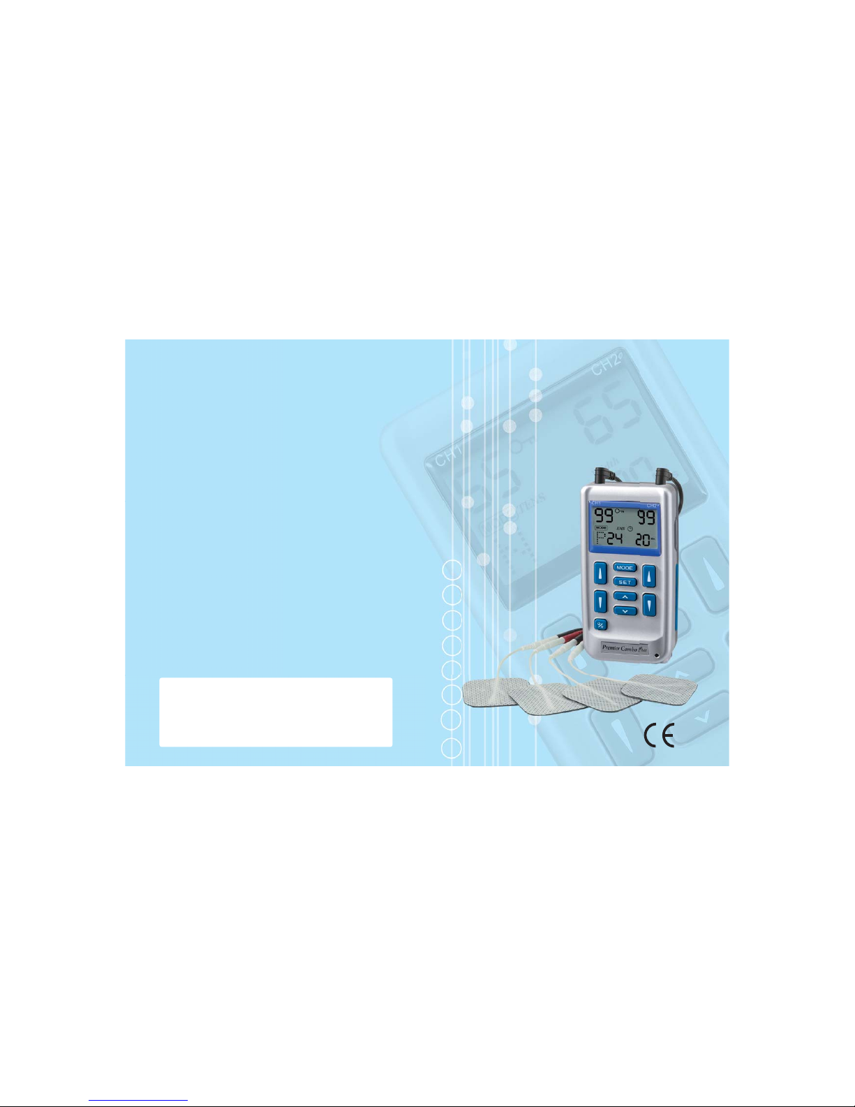
The Premier Combo Plus TENS/EMS is a fully digital battery oper-
ated pulse generator that sends electrical impulses to the nerves
and underlying muscle groups. This unit is a combination stimulator
of TENS and EMS which can be used for pain relief and muscle
stimulation. The device is provided with two controllable output
channels, each independent of the other. A pair of electrodes can
be connected to each output channel. The intensity level and set-
tings are controlled by press buttons
Chapter 2 : INTRODUCTION
EXPLANATION OF PAIN
Pain is a warning system and the body’s method of telling us that
something is wrong. Pain is important; without it abnormal condi-
tions may go undetected, causing damage or injury to vital parts of
our bodies.
Even though pain is a necessary warning signal of trauma or mal-
function in the body, nature may have gone too far in its design.
Aside from its value in diagnosis, long-lasting persistent pain serves
no useful purpose. Pain does not begin until coded messages
travel to the brain where they are decoded, analyzed, and reacted
to. The pain message travels from the injured area along the small
nerves leading to the spinal cord. Here the message is switched to
different nerves that travel up the spinal cord to the brain. The pain
message is interpreted and pain is perceived.
EXPLANATION OF TENS
Transcutaneous Electrical Nerve Stimulation is a non-invasive, drug-
free method of controlling pain. TENS uses tiny electrical impulses
sent through the skin to nerves to modify your pain perception.
TENS does not cure any physiological problem; it only helps control
the pain. TENS does not work for everyone; however, in most pa-
tients it is effective in reducing or eliminating the pain, allowing for a
return to normal activity.

54
9. Turn the TENS off before applying or removing electrodes.
10. Isolated cases of skin irritation may occur at the site of electrode
placement following long term application. If this occurs,
discontinue use and consult your physician.
11. If TENS therapy becomes ineffective or unpleasant, stimulation
should be discontinued until its use is re-evaluated by a physician
12. Keep this device out of the reach of children.
13. The device has no AP/APG protection.
Do not use it in the presence of explosive atmosphere and
ammable mixture.
EMS
1. Federal law (USA) restricts this device to sale by or on the
order of a physician
2. Safety of powered muscle stimulators for use during pregnancy
has not been established.
3. Caution should be used for patients with suspected or diagnosed
heart problems.
4. Caution should be used for patients with suspected or diagnosed
epilepsy.
5. Caution should be used in the presence of the following:
a. When there is a tendency to hemorrhage following acute
trauma or fracture;
b. Following recent surgical procedures when muscle
contraction may disrupt the healing process;
c. Over the menstruating or pregnant uterus; and
d. Over areas of the skin which lack normal sensation.
6. Some patients may experience skin irritation or hypersensitivity
due to the electrical stimulation or electrical conductive medium.
The irritation can usually be reduced by using an alternate
conductive medium, or alternate electrode placement.
7. Electrode placement and stimulation settings should be based
on the guidance of the prescribing practitioner.
8. Powered muscle stimulators should be kept out of the reach of
children.
9. Powered muscle stimulators should be used only with the leads
and electrodes recommended for use by the manufacturer.
10. Portable powered muscle stimulators should not be used while
driving, operating machinery, or during any activity in which
involuntary muscle contractions may put the user at undue risk
of injury.
should only be used under medical supervision for adjunctive thera-
py for the treatment of medical diseases and conditions.
IMPORTANT SAFETY INFORMATION
Read instruction manual before operation. Be sure to comply with
all “CAUTIONS” and “WARNINGS” in the manual. Failure to follow
instructions can cause harm to user or device.
Chapter 3 : CAUTIONS
TENS
1. Federal law (USA) restricts this device to sale by or on the
order of a physician.
2. Do not use this device for undiagnosed pain syndromes until
consulting a physician.
3. Patients with an implanted electronic device, such as a cardiac
pacemaker, implanted debrillator, or any other metallic or
electronic device should not undergo TENS treatment without
rst consulting a doctor.
4. Patients with heart disease, epilepsy, cancer or any other health
condition should not undergo TENS treatment without rst
consulting a physician.
5. Stimulation delivered by this device may be sufcient to cause
electrocution. Electrical current of this magnitude must not ow
through the thorax or across the chest because it may cause a
cardiac arrhythmia.
6. Do not place electrodes on the front of the throat as spasm of
the Laryngeal and Pharyngeal muscle may occur. Stimulation
over the carotid sinus (neck region) may close the airways,
make breathing difcult, and may have adverse effects on the
heart rhythm or blood pressure.
7. Do not place electrodes on your head or at any sites that may
cause the electrical current to ow transcerebrally (through the
head).
8. This device should not be used while driving, operating
machinery, close to water, or during any activity in which
involuntary muscle contractions may put the user at undue risk
of injury.

76
Chapter 7 : CONSTRUCTION
FRONT
(1) LEAD CONNECTOR
(2) ON/OFF/PAUSE CONTROL
(3) LIQUID CRYSTAL DISPLAY
(4) MODE CONTROL
(5) SET CONTROL
(6) SETTING INCREMENT CONTROL
(7) SETTING DECREMENT CONTROL
(8) INTENSITY INCREMENT CONTROL
(9) INTENSITY DECREMENT CONTROL
Chapter 4 : WARNINGS
1. The long-term effects of chronic electrical stimulation are
unknown.
2. Stimulation should not be applied over the carotid sinus nerves,
particularly in patients with a known sensitivity to the carotid
sinus reex.
3.
Stimulation should not be applied over the neck or mouth. Severe
spasm of the laryngeal and pharyngeal muscles may occur and
the contractions may be strong enough to close the airway or
cause difculty in breathing.
4. Stimulation should not be applied transthoracically in that the
introduction of electrical current into the heart may cause cardiac
arrhythmias.
5. Stimulation should not be applied transcerebrally.
6. Stimulation should not be applied over swollen, infected, or
inamed areas or skin eruptions, e.g., phlebitis, thrombophlebitis,
varicose veins, etc.
7. Stimulation should not be applied over, or in proximity to,
cancerous lesions.
Chapter 5: CONTRAINDICATION
Electrical stimulators should not be used on patients with cardiac
demand pacemakers.
Chapter 6: ADVERSE REACTIONS
On rare occasions skin irritation and burns beneath the electrodes
have been reported with the use of electrical stimulators. If irritation
occurs, discontinue use and consult your physician.

98
Chapter 8 : TECHNICAL SPECIFICATIONS
The technical specication details of Premier Combo Plus Digital
TENS/EMS are as follows:
MECHANISM TECHNICAL DESCRIPTION
01 Channel Dual, isolated between channels
02 Pulse Amplitude Adjustable, 0-100 mA peak into 500 ohm
load each channel.
03 Wave Form
Asymmetrical Bi-Phasic Square Pulse
04 Voltage 0 to 50V (Load: 500 ohm)
05 Power source One 9 Volt Battery.
06 Size 11.8cm(L) x 6 cm(W) x 3.1cm(H)
07 Weight 157 grams with battery.
08 Pulse Rate Adjustable, from 2 to 150 Hz, 1 Hz/step
09 Pulse Width Adjustable, from 50 to 300 microseconds,
10 µs/step
10 On Time Adjustable, 2~90 seconds , 1 Sec./ step
11 Off Time Adjustable, 2~90 seconds , 1 Sec./ step
12 Ramp Time Adjustable, 1~8 seconds, 1 Sec./ step, The
“On” time will increase and decrease in
the setting value.
13 Mode Six TENS Modes: B(Burst), N(Normal),M
(Modulation Rate & Width),S1( Modulation
Width), S2 (Modulation Width) and P
Three EMS Modes:C(Constant), S
(Synchronous), A(Alternate)
14 Burst Mode Burst rate: Adjustable, 0.5 – 5Hz
Pulse width adjustable, 50~300µs
Frequency xed = 100 Hz
15 Normal Mode The pulse rate and pulse width are
adjustable. It generates continuous
stimulation based on the setting value.
16 Modulation Mode Modulation mode is a combination of pulse
rate and pulse width modulation. The pulse
rate and width are automatically varied in
a cycle pattern. The pulse width is
decreased by 50% from its original setting
BACK SIDE
BACK
(10) BELT CLIP
(11) BATTERY STRIP
(12) BATTERY CASE
SIDE
(13) KEY LOCK FACILITY
Liquid Crystal Display
1. INTENSITY LEVEL
2. MODE
3. SETTINGS
4. STIMULATION TYPE
5. LOW BATTERY INDICATOR
6. LOCK

1110
time. The OFF Time should be equal to or
greater than the ON Time.
ON TIME ≥Ramp up + Ramp down
OFF TIME ≥ON TIME
22 Mode P The pre-set parameters of the 24
programs are as given below:
Program The pre-set parameters of the TENS 1-12
Details programs are as given below:
Program Mode Pulse Rate
Pulse Width
Timer
P1 Constant 80Hz 180µs Continue
P2 Burst 2Hz 180µs Continue
P3 P.W. 80Hz 70µs -180µs Continue
Modulation
P4 Mixed
15Hz in 3 Sec /
180µs Continue
Frequency 2Hz in 3 Sec
P5 Mixed
80Hz in 3 Sec /
180µs Continue
Frequency 2Hz in 3 Sec
P6 Constant 10Hz 180µs Continue
P7 Constant 80Hz 60µs Continue
P8 Constant 10Hz 200µs
30 Minutes
P9 Burst 50Hz 250µs 30 Minutes
P10
on Time Pause Time Frequency Pulse Width Sub- Active Pulse
(sec) (sec) (Hz) (µs) Pulse Channels Polarity
2 0 5 120 No CH1 & CH2 Positive
1.5 0 8 120 No CH1 & CH2 Positive
1.4 0 10 120 No CH1 & CH2 Positive
1 0 15 120 No CH1 & CH2 Positive
0.8 0 20 120 No CH1 & CH2 Positive
0.7 0 30 120 No CH1 & CH2 Positive
0.7 0 40 120 No CH1 & CH2 Positive
0.7 0 50 120 No CH1 & CH2 Positive
1 0 75 120 No CH1 & CH2 Positive
in 0.5 second, then the pulse rate is
decreased by 50% from its original setting
in 0.5 second. Total cycle time is 1 second.
In this mode, pulse rate(2-150Hz) and
pulse
width(50-300µs) are fully adjustable.
17 S1 Mode Pulse width is automatically varied in a
cyclic pattern over a nominal 10 second
period. Pulse width decreases over a
period of 4 seconds from the initial setting
to a value 40% less.
The narrower pulse width continues for 1
second. It then increases over a period of
4 seconds to its initial setting. The cycle is
then repeated. Pulse rate and pulse width
are fully adjustable.
18 S2 Mode Pulse width is automatically varied in a
cyclic pattern over a nominal 10 second
period. Pulse width decreases over a
period of 4 seconds from the initial setting
to a value 70% less.
The narrower pulse width continues for 1
second. It then increases over a period of
4 seconds to its initial setting. The cycle is
then repeated. Pulse rate and pulse width
are fully adjustable.
19 Constant The pulse rate and pulse width are
Mode(C) adjustable. It generates continuous
stimulation is delivered .
20 Synchronous Output from both channels occurs
Mode(S) synchronously. The "ON" time includes
"Ramp Up" and "Ramp Down" time.
Therefore, the setting of ON Time should
be no less than two times of the "Ramp"
time in this mode.
21 Alternate The stimulation of the CH2 will occur after
Mode(A) the 1st contraction of CH1 is completed. In
this mode, the setting of ON Time should
be no less than two times of the "Ramp"

1312
0.7 0 100 120 No CH1 & CH2 Positive
1 0 125 120 No CH1 & CH2 Positive
0.7 0 100 120 No CH1 & CH2 Positive
1 0 75 120 No CH1 & CH2 Positive
0.7 0 50 120 No CH1 & CH2 Positive
0.7 0 40 120 No CH1 & CH2 Positive
0.7 0 30 120 No CH1 & CH2 Positive
0.8 0 20 120 No CH1 & CH2 Positive
1 0 15 120 No CH1 & CH2 Positive
1.4 0 10 120 No CH1 & CH2 Positive
1.5 0 8 120 No CH1 & CH2 Positive
P11 Modulation 2-100Hz 260µs-150µs Continue
Rate & width
over 6 seconds
P12 Modulation 80< - >7Hz 260µs Continue
Rate & width
over 6 seconds
Program The pre-set parameters of the EMS 13-24
Details programs are as given below:
Mode SYN/ Rate Width Ramp ON Time Off Time Timer
ALT (Hz) (µs) (Sec) (Sec) (Sec) (Min)
P13 ACL repair/joint SYN 35 300 3 8 24 20
protection back muscle
P14 Spasm small SYN 80 300 3 10 5 20
muscle
P15 Spasm SYN 80 250 2 8 4 20
Postoperative
P16 Arthroscopy SYN 25 200 2 6 30 15
P17 Disuse atrophy SYN 35 300 2 5 15 30
P18 Shoulder SYN 50 300 5 15 50 15
Subluxation
P19 Range of motion SYN 40 250 3 6 21 30
muscle re-education of hips
P20 Muscle training SYN 50 250 2 10 10 20
P21 Muscle training SYN 50 250 2 14 14 20
P22 Muscle training SYN 35 400 2 10 10 20
P23 Muscle training ALT 50 250 2 10 10 20
P24 Muscle training ALT 50 250 2 10 14 20
23 Timer
Adjustable, from 5 to 60 minutes minutes
and continue(C), 5 minutes each step
24 Patient This unit can store 60 sets of operation
Compliance Meter records. Total recorded time is 999 hours.
25 Low Battery A low battery indicator will show up when
Indicator the battery is low.
26 Operating Temperature:0°~40°C
Condition Relative Humidity: 30%~75%
Atmosphere Pressure : 700Hpa~1060Hpa
27 Remark There may be up to a +/-10% tolerance of
all parameters and +/-20% tolerance of
output amplitude & voltage.

1514
The waveforms of the TENS modes are as follows.
1. Burst
2. Normal
3. Modulation
4. S1 (Strength-Duration)
5. S2 (Strength-Duration)
Chapter 9 : REPLACEABLE PARTS
The replaceable parts and accessories of Premier Combo Plus Digi-
tal TENS/EMS devices are as given below.
Except lead wires and electrodes, please do not try to replace the
other parts of a device.
PARTS
1. Lead Wires
2. Electrodes
3. Belt Clip
4. Lead Connector
5. Main PCB
6. Press Buttons
7. LCD Cover
8. 9V Battery
9. Device Case
Chapter 10 : ACCESSORIES
Each Premier Combo Plus Digital TENS/EMS comes complete with
standard accessories and the standard labels as given below:
I. Accessories
REF. NO. DESCRIPTION Q’TY
1. KF4040 40x40mm Adhesive Electrodes 4 pieces
2. KE-24 Electrodes Leads 2 pieces
3. GC-01 9 V Battery, type 6F22 1 piece
4. Instruction Manual 1 piece
5. Carrying Case 1 piece

1716
II. LABEL
The label attached to the back of device con-
tains important information about this device-
model, supply voltage, CE number and cau-
tion. Please do not remove.
III. Serial Number(YYWWXXXX)
The serial number of the device is put on the back of the unit.
There are 8 digits in the number.
The rst 2 digits represent the year the unit is produced. For
example, “16” means 2016. The second 2 digits means the
week number.
The last 4 digits means the serial number of unit produced in
that week. Please always tell your distributor the serial number
of the device if you have any question about the device.
Chapter 11 : GRAPHIC SYMBOLS
1. Degree of Electrical Protection BF
2. Do not insert the plug into AC power supply socket.
3. Timer
4. Increment
5. Decrement
7. Consult Instructions for use
8. Manufacturer
9. Serial Number
10. Lock
11. Low Battery
12. Pause
13. DC Current(DC Power source)
14.
Comply with MDD 93/42/EEC requirements as amended
by 2007/47/EC. Notify body Det Norske Veritas(DNV).
15. Power
Chapter 12: OPERATING INSTRUCTIONS
1) Insert the 9V battery into the device's battery compartment.
Make sure that the plastic seal on the 9V battery is removed.
Line up the positive and negative terminals on the battery with
their corresponding terminals in the device. Make sure that the
unit is turned off.
2) Insert the lead wires into the lead wire sockets on top of the
device.
3) Open the electrode package. Then insert each lead wire pin
into the pig tail of the electrodes
4) Place the electrode on your body as
directed by your physician.
5) Turn on the power by pressing the
power On/Off/Pause button.
6) Select the mode and settings as
directed by your physician.
7) Slowly increase or decrease the
intensity by pressing the intensity
control buttons.
8) You may press the On/Off/Pause
button if you want to stop treatment
for a while.
9) After treatment, turn the device off
by pressing the On/Off/Pause button.
Chapter 13 : PARAMETER CONTROLS
PULSE DURATION
Wider pulse duration settings will deliver stronger stimulation for
any given intensity setting. As mentioned in the Controls section, by

1918
using a combination of intensity and pulse duration different nerve
bres are stimulated.
The wider pulse duration is needed to recruit motor bres, whereas
the narrow pulse duration is used on the more sensory bres. The
choice of which pulse duration to use is partially dependent upon
the Treatment Mode and Protocol selected.
PULSE RATE
The Pulse Rate (hertz or pulses per second) chosen depends great-
ly upon the type of electrode placement given to the patient.
When using contiguous and dermatome electrode placements (i.e.
stimulating directly through the area of pain or localized innnerva-
tion), a higher pulse rate (setting greater than 80Hz on the Pulse
Rate Control) is required. The patient should not perceive individual
pulses but rather have the sensation of steady continuous stimulation.
When using point treatments, it has been suggested that lower
pulse rates be utilized (less than 10Hz). With this setting the patient
should be able to perceive individual pulses.
When using multiple electrode placement strategies, such as com-
binations of point and contiguous electrode placements, the higher
pulse rates are suggested.
Despite the above recommendations, individual patients may re-
quire slight variations of the above settings, according to the nature
of their condition.
TREATMENT MODE
Normal or Conventional TENS offers the practitioners complete con-
trol over all the various treatment parameters of the instrument.
Burst Mode is analogous to the Low Rate TENS technique except
the low frequency individual pulses are replaced by individual “bursts”
of 7-10 individual pulses. It is thus a combination of Conventional
TENS and Low Rate TENS. In Burst Mode, the treatment frequency
is adjustable at the range between 0.5Hz ~ 5Hz.
Modulated Mode attempts to minimise nerve accommodation by
continuously cycling the treatment intensity. Advise the patient to
increase the intensity very slowly when using modulation mode.
INTENSITY
Each patient responds differently to different levels of intensity, due
to varying degrees of tissue resistance, enervation, skin thickness,
etc. Intensity instructions are therefore limited to the following settings:
Perception – The intensity is increased so that the patient can feel
the stimulation, but there is not any muscular contraction.
Slight Contraction – Intensity is increased to a barely visible muscu-
lar contraction that is not strong enough to move a joint. When us-
ing low pulse rate settings, this will show as individual twitches. At
higher pulse rates there will simply be increased muscle tension.
Strong muscular contraction is typically not used in TENS therapy.
However, muscular contraction may be useful if the pain involves a
cramped or spastic muscle. The TENS can be used as a traditional
muscle stimulator in the circumstances to quickly break the spasm.
Use a higher pulse rate, wide pulse duration and set the intensity
to visible contraction (still within patient tolerance). Twenty or thirty
minutes of such a tetanized muscular contraction will generally
break the spasm. In all cases, if the patient complains that the stim-
ulation is uncomfortable, reduce intensity and/or cease stimulation.
TIME DURATION
The onset of pain relief should occur shortly after the intensity set-
ting has been determined. However, in some cases, pain relief may
take as long as 30 minutes to achieve, especially when using point
electrode placements and slow pulse rates.
TENS units are typically operated for long periods of time, with a
minimum of 20 ~ 30 minutes and in some post-operation protocols,
as long as 36 hours.
In general, pain relief will diminish within 30 minutes of the ces-
sation of stimulation. Pain relief obtained through point electrode
placements may last longer (perhaps because of the presence of
endorphins).

2120
CONTRACTION / RELAXATION
The contraction time and relaxation time of EMS is adjustable.
Stimulation will commence at the contraction setting time and cease
at the relaxation setting time. Then the cycle starts over again -
Stimulation, Contraction and Relaxation.
RAMP
In order to achieve a comfortable exercise and avoid discomfort be-
cause of immediate current onset, each contraction may be ramped
so that the signal comes on gradually and smoothly. The intensity of
electrical current will reach the set level within the Ramp time. It will
NOT reach the desired level if the ramp time is greater than the total
contraction time.
OUTPUT MODE
The output of both channels are adjustable. Stimulation can be
synchronous or alternate. Stimulation of both channels will occur at
the same time when synchronus pattern is selected. In alternating
mode, the stimulation from CH2 will occur after contraction of Ch1 is
nished.
Chapter 14 : ATTACHMENT OF ELECTRODE
LEAD WIRES
The wires provided with the
system insert into the jack
sockets located on top of the
device. Holding the insulated
portion of the connector, push
the plug end of the wire into
one of the jacks (see drawing);
one or two sets of wires may
be used.
After connecting the wires to the stimulator, attach each wire to an
electrode. Use care when you plug and unplug the wires. Jerking
the wire instead of holding the insulated connector body may cause
wire breakage.
CAUTION
Do not insert the plug of the patient lead wire into any AC power
supply socket.
Chapter 15: LEAD WIRE MAINTENANCE
Clean the wires by wiping with a damp cloth. Coating them lightly
with talcum powder will reduce tangling and prolong life.
Chapter 16 : ELECTRODE OPTIONS
The electrodes are disposable and should be routinely replaced
when they start to lose their adhesive nature. If you are unsure of
your electrode adhesive properties, order replacement electrodes.
Replacement electrodes should be re-ordered through or on the
advice of your physician to ensure proper quality. Follow application
procedures outlined in electrode packing, to maintain optimal stimu-
lation and to prevent skin irritation.
Chapter 17: ELECTRODE PLACEMENT
The placement of electrodes can be one of the most important
parameters in achieving success with TENS or EMS therapy. It
is important that the physician experiments to determine optimum
electrode placement.
Every patient responds to electrical stimulation differently and their
needs may vary from the conventional settings suggested here. If

2322
the initial results are not positive, speak to your physician about al-
ternative stimulation settings and/or electrode placements. Once an
acceptable placement has been achieved, mark the electrode sites
and the settings, so that effective treatment may effectively continue
at home.
Chapter 18: TIPS FOR SKIN CARE
To avoid skin irritation, especially if you have sensitive skin, follow
these suggestions:
1. Wash the area of skin where you will be placing the electrodes,
using mild soap and water before applying electrodes, and after
taking them off. Be sure to rinse soap off thoroughly and dry
skin well.
2. Excess hair may be clipped with scissors; do not shave
stimulation area.
3. Wipe the area with the skin preparation your physician has
recommended. Let this dry. Apply electrodes as directed.
4. Many skin problems arise from the “pulling stress” from adhesive
patches that are excessively stretched across the skin during
application. To prevent this, apply electrodes from center
outward; avoid stretching over the skin.
5. To minimize “pulling stress”, tape extra lengths of lead wires to
the skin in a loop to prevent tugging on electrodes.
6. When removing electrodes, always remove by pulling in the
direction of hair growth.
7. It may be helpful to rub skin lotion on electrode placement area
when not wearing electrodes.
8. Never apply electrodes over irritated or broken skin.
Chapter 19: APPLICATION OF RE-USABLE SELF
ADHESIVE ELECTRODES
Application
1. Clean and dry the skin at the prescribed area thoroughly with
soap and water prior to application of electrodes.
2. Insert the lead wire into the pin connector on the pre-wired
electrodes.
3. Remove the electrodes from the protective liner and apply the
electrodes rmly to the treatment site. Make sure that the unit is
turned off prior to applying the electrodes.
Removal
1. Turn off the unit prior to removing the
electrodes.
2. Lift at the edge of electrodes and peel;
do not pull on the lead wires because it
may damage the electrodes.
3. Place the electrodes on the liner and
remove the lead wire by twisting and
pulling at the same time.
Care and Storage
1. Between uses, store the electrodes in the resealable bag in a
cool dry place.
2 . It may be helpful to improve repeated application by spreading a
few drops of cold water over the adhesive and turn the surface
up to air dry. Over Saturation with water will reduce the adhesive
properties.
Important
1. Do not apply to broken skin.
2. The electrodes should be discarded and re-ordered from your
physician when they are no longer adhering.
3. The electrodes are intended for single patient use only.
4. If irritation occurs, discontinue use and consult your physician.
5. Read the instructions for use of self-adhesive electrodes before
application.

2524
Chapter 20 : ADJUSTING THE CONTROLS
1. Power On/Off/Pause Button
The power of unit can be turned on by pressing the On/Off/
Pause button. You may start to adjust the settings when the
liquid crystal is light up. Press and hold for 2 seconds to switch
off. To pause stimulation press the button once. To resume
stimulation press the button again and stimulation will be restored
in 2 seconds.
If the unit is not used (buttons not pressed or output level at 0)
for 5 minutes, the power will be shut off automatically.
If the unit is not used(buttons not pressed or output level at 0) for 5
minutes, the power will be shut off automatically
2. Lead Connector
Connection of the electrodes is made with the two-lead connector
(lead wires) on the top of unit. The device must be turned off
before connecting
the cables.
Electrodes must be in
rm contact
with the skin.
Pause
3 Mode Control
There are 5 TENS modes(B, N, M, S1, S2) and 3 EMS modes
(C, S, A) available. The mode is selected by pressing the “Mode”
control. When a TENS mode is selected, the LCD shows
"TENS". When EMS mode is selected, the LCD shows "EMS"
4. Set Control
By pressing the "Set" control you select the
setting you intend to adjust. The value is set
by pressing the "Increment" or "Decrement"
controls when the "Set" value is ashing.
5. Increment Control
This button controls the increase of settings.
6. Decrement Control
This button controls the decrease of settings.
7. Intensity Increase Control
The intensity level can be increased by pressing this button.
There are 99 steps of intensity adjustment control. Press the
button until the desired intensity level is reached.
8. Intensity Decrease Control
The intensity level can be decreased by pressing this button.
There are 99 steps of intensity adjustment control. Press the
button until the desired intensity level is reached.
9. Key Lock Facility
Pressing the "Lock" buttons prevents the settings

2726
being changed but the output may be stopped by
pressing the "On/Off/Pause".
10. Steps to Set a TENS Program
The settings can be adjusted as follows
a. Turn on the Power
After the electrodes are placed rmly on skin and
the lead wires are plugged in the socket of device,
turn the unit on by pressing the On/Off/Pause
button. The settings will be displayed on the LCD
screen.
b. Select a Mode or a Preset Programme
Select a mode by pressing the "Mode" control.
The mode you selected will show up on the top of liquid
crystal display. There are 5 modes of your option including -
B(Burst), M(Normal), M(Modulation), S1, S2 and P. When a
TENS mode is selected, it shows "TENS" on the liquid crystal
display.
After a mode is selected, always press "Set" to enter next
setting, and press " " or " " to adjust its value.
The settings will be stored immediately after selected.
There are 12 preset programs of your option on P mode.
Press " " or " " to select a program desired
after P mode is selected. These programs are not adjustable.
c. Set Pulse Width
Pulse Width is adjustable from 50 µs to 300 µs. Press “SET”
control to enter this menu, then press “ ” or “ “
to adjust the setting. If no instructions regarding the pulse
width are given in therapy, set the control to the suggested
70-120 µs setting.
d. Set Pulse Rate
Pulse rate is adjustable from 2Hz to 150 Hz . Press "SET"
control to enter this menu, then press " " or " "
to adjust the setting. Unless otherwise instructed, set the
pulse rate l to the 70-120 Hz range.
e. Set Timer
The treatment time is adjustable between 5 - 60 minutes and
Continue(C). Press "SET" control to enter this menu, then
press " " or " " to
adjust the setting. The liquid
crystal will show the balance treatment time after the
stimulation is started. Output will be terminated when time
is up. Turn off the unit when the output is off.
Continuous End of Treatment

2928
f. Adjust Intensity
There are 99 steps within the intensity range. Set the desired
level by pressing the " " or " " controls. Press the
"Lock" button to prevent accidental changes.
11. Steps to Set a EMS Program
The settings can be adjusted according to the following steps.
a. Turn on the Power
After the electrodes are placed rmly on skin and the lead
wires are plugged in the socket of device, turn the unit on by
pressing the On/Off/Pause button. The settings will show
up on LCD for your further adjustment.
b. Select a Mode or a Preset Programme
Select a mode by pressing the "Mode" control. The mode you
selected will show up on the top of liquid crystal display.
There are 3modes of your option including -
C(Constant), S(Synchronous), A(Alternate). When an EMS
mode is selected, it shows "EMS" on the liquid crystal display.
After a mode is selected, always press "Set" to enter next
setting, and press " " or " " to adjust its value.
The settings will be stored immediately after selected.
After a mode is selected, always press “Set” to enter next
setting, and press “ “ or “ “ to adjust its value.
The settings will be stored immediately after selected.
There are 12 preset programs of your option on P mode.
Press “ “ or “ “ to select a program desired
after P mode is selected. These programs are not adjustable.
c. Set Ramp Time
The ramp time controls the time taken to reach maximum and
the time taken to fall to zero I order to make the contraction
more comfortable. The ramp time is adjustable between 1 - 8
seconds.
d. Set On Time
The On Time controls the length of stimulation. By pressing
the "Set" control, the contraction time can be adjusted. Both
channels' stimulation is cycled on and off by the contraction
and relaxation settings. The range is adjustable from 2
seconds to 90 seconds.
The total "ON" time must be at least twice the "Ramp" time

3130
e. Set Off Time
The Off Time controls the length of relaxation. By pressing
the "SET" control, the relaxation time can be adjusted. Both
channels' stimulation is cycled on and off by the contraction
and relaxation settings. The range is adjustable from 2
seconds to 90 seconds.
In Alternate mode, the OFF Time should be equal or more than
the ON Time. (OFF TIME ≥ ON TIME)
f. Set Pulse Width
Pulse Width is adjustable from 50 µs to 300 µs. Press "SET"
control to enter this menu, then press " " or " "
to adjust the setting. If no instructions regarding the pulse
width are given in therapy, set the control to the suggested
70-120 µs setting
g. Set Pulse Rate
Pulse rate is adjustable from 2Hz to 150 Hz . Press "SET"
control to enter this menu, then press " "or " "
to adjust the setting.
Unless otherwise instructed, set the pulse rate to the 70-
120 Hz range.
h. Set Timer
The treatment time is adjustable between 5 - 60 minutes and
Continue(C). Press "SET" control to enter this menu, then
press "Increment" or "Decrement" to adjust the setting. The
liquid crystal will show the balance treatment time after the
stimulation is started. Output will be terminated when time is
up. Turn off the unit when the output is off.
i. Adjust Intensity
There are 99 steps within the intensity range. Set the desired
level by pressing the " " or " " controls. Press the
"Lock" button to prevent accidental changes.
12. Compliance Meter
The individual treatment time and total treatment time can be
checked and deleted by the following steps. Sixty sets of
treatment records can be stored. Total recorded time is 999
hours.
Check & Delete Treatment Record
Press "Mode" control and turn on the power simultaneously.
The LCD will show the individual operation time. Press "Mode"
control to check the accumulated treatment time. The record
can be deleted by pressing the "SET" button for two seconds.
Continuous End of Treatment

3332
13. Check/Replace the Battery:
Over time, in order to ensure the functional safety of TENS/
EMS, changing the battery is necessary.
1. Make sure that both intensity controls
are switched to off
position.
2. Slide the battery compartment cover
and open.
3. Remove the battery from the
compartment.
4. Insert the battery into the
compartment. Note the polarity
indicated on the battery and in the
compartment.
5. Replace the battery compartment
cover and press to close.
Chapter 21: BATTERY INFORMATION
PRECATIONS
1. Remove battery if equipment is not likely to be used for some
time.
2. Please recycle the used battery in accordance with domestic
regulation.
3. Do not throw the used battery into re.
If you use rechargeable batteries, please follow the instructions.
RECHARGEABLE BATTERIES(NOT INCLUDED)
Prior to the use of a new unit, the rechargeable battery should be
charged according to the battery manufacturer’s instructions. Be-
fore using the battery charger, read all instructions and cautionary
markings on the battery and in this instruction manual.
After being stored for 60 days or more, the batteries may lose their
charge. After long periods of storage, batteries should be charged
prior to use.
BATTERY CHARGING
(1) Plug the charger into any working 110 or 220/240v mains
electrical outlet. The use of any attachment not supplied with
the charger may result in the risk of re, electric shock, or
injury to persons.
(2) Follow the battery manufacturer’s instructions for charging time.
(3) After the battery manufacturer’s recommended charging time
has been completed, unplug the charger and remove the battery.
(4) Batteries should always be stored in a fully charged state.
To e n sure o p timum bat t ery p e r forma n c e, fo l l ow th e s e gui d eli n es:
(a) Although overcharging the batteries for up to 24 hours will
not damage them, repeated overcharging may decrease
useful battery life.
(b) Always store batteries in their charged condition. After a
battery has been discharged, recharge it as soon as
possible. If the battery is stored more than 60 days, it may
need to be recharged.
(c) Do not short the terminals of the battery. This will cause the
battery to get hot and can cause permanent damage. Avoid
storing the batteries in your pocket or purse where the
terminals may accidentally come into contact with coins,
keys or any metal objects.
(d) WARNINGS:
1. Do not attempt to charge any other types of batteries in
your charger, other than rechargeable batteries made
Individnal Record Accumulated

3534
for your charger. Other types of batteries may leak or
burst.
2. Do not incinerate the rechargeable battery as it may
explode!
Chapter 22 : MAINTENANCE, TRANSPORTATION
AND STORAGE
1. Non-ammable cleaning solution is suitable for cleaning the
device.
Note: Do not smoke or work with open lights (for example,
candles, etc.) when working with ammable liquids.
2. Stains and spots can be removed with a cleaning agent.
3. Do not submerge the device in liquids or expose it to large
amounts of water.
4. Return the device to the carrying box with sponge foam to
ensure that the unit is well-protected before transportation.
5. If the device is not to be used for a long period of time, remove
the batteries from the battery compartment (acid may leak from
used batteries and damage the device). Put the device and
accessories in carrying box and keep it in cool dry place.
6.
The packed device should be stored and transported under
the temperature range of -20°C ~ + 60°C, relative humidity 20%
~95%, atmosphere pressure 500 hPa ~ 1060 hPa.
Chapter 23: SAFETY-TECHNICAL CONTROLS
For safety reasons, review the following checklist before using your
Premier Combo Plus DIGITAL TENS/EMS.
1. Check the device for external damage.
- deformation of the housing.
- damaged or defective output sockets.
2. Check the device for defective operating elements.
- legibility of inscriptions and labels.
- make sure the inscriptions and labels are not distorted.
3. Check the usability of accessories.
- patient cable undamaged.
- electrodes undamaged.
- Battery is not corroded
Please consult your distributor if there are any problems with device
and accessories.
Chapter 24 : MALFUNCTIONS
Should any malfunctions occur while using the Premier Combo Plus
Digital TENS/EMS, check
- whether the parameters are set to the appropriate form of therapy.
Adjust the control correctly.
- whether the cable is correctly connected to the device. The
cables should be inserted completely into the sockets.
- whether the LCD reveals the menu. If necessary, insert a new
battery.
- f
or possible damage to the cable. Change the cable if any damage
is detected.
* If there is any other problem, please return the device to your
distributor. Do not try to repair a defective device.
Chapter 25: CONFORMITY TO SAFETY
STANDARDS
The Premier Combo Plus DIGITAL TENS/EMS devices are in com-
pliance with the following standards.
EN60601-1-2:2007, IEC60601-1-2:2007 Medical electrical equipment -
Part 1-2: General requirements for basic safety and essential per-
formance

3736
-Collateral standard: Electromagnetic compatibility - Requirements
and tests
EN60601-1:2006, IEC60601-1:2005 Medical electrical equipment -
Part 1: General requirements for basic safety and essential Perfor-
mance
Chapter 26 : WARRANTY
All Premier Combo Plus Digital TENS/EMS models carry a
warranty
of one year from the date of delivery. The warranty applies to the
stimulator only and covers both parts and labour relating thereto.
The warranty does not apply to damage resulting from failure to
follow the operating instructions, accidents, abuse, alteration or dis-
assembly by unauthorized personnel.
Chapter 27: ELECTROMAGNETIC COMPATIBILITY
INFORMATION
The device complies with current specications with regard to elec-
tromagnetic compatibility and is suitable for use in all premises,
including those designated for private residential purposes. The
radio frequency emissions of the device are extremely low and in all
probability do not cause any interference with other devices in the
proximity.It is recommended that you do not place the device on top
of or close to other electronic devices. Should you notice any inter-
ference with other electrical devices, move the device or connect it
to a different socket. Radio equipment may affect the operation of
this device.
Guidance and manufacturer’s declaration - electromagnetic emissions
The EM-6300A is intended for use in the electromagnetic environment
specied below. The customer or the user of the EM-6300A should
assure that it is used in such an environment.
Emissions test Compliance Electromagnetic environment -
guidance
RF emissions Group 1 The EM-6300A must emit electromag-
netic energy in order to perform its
CISPR 11 intended function. Nearby electronic
equipment may be affected.
RF emissions Class B The EM-6300A is suitable for use in all
CISPR 11 establishments other than domestic
Harmonic emissions Class C those directly connected to the public
IEC 61000-3-2 low-voltage power supply network that
Voltage uctuations Complies supplies buildings used for domestic
/ icker emissions purposes.
IEC 61000-3-3
Table of contents
Other Mars One Fitness Equipment manuals