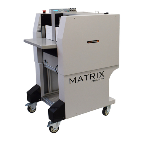
GALA D-12 A User manual

GALA INDUSTRIAL
EMANUAL TÉCNICO DE INSTRUCCIONES.
DEVANADORAS DE HILO DE REGULACIÓN ELECTRÓNICA.
GB TECHNICAL INSTRUCTIONS MANUAL.
ELECTRONIC ADJUSTMENT WIRE-FEED UNIT.
F MANUEL TECHNIQUE D'INSTRUCTIONS.
DÉVIDOIRS DE FIL À RÉGLAGE ÉLECTRONIQUE.
P MANUAL TÉCNICO DE INSTRUÇÕES.
DESBOBINADOR DE FIO DE REGULAÇÃO ELECTRÓNICA.
D-12 A
Ref. 618.00.000
D-20 A
Ref. 621.00.000
D-20 AR
Ref. 622.00.000
E ESTE EQUIPO DEBE SER UTILIZADO POR PROFESIONALES.
EN BENEFICIO DE SU TRABAJO LEA ATENTAMENTE ESTE MANUAL.
GB THIS EQUIPMENT MUST BE USED BY PROFESSIONALS.
TO HELP YOU IN YOUR WORK CAREFULLY READ THIS MANUAL.
F CET ÉQUIPEMENT DOIT ÊTRE UTILISÉ PAR DES PROFESSIONNELS.
POUR OBTENIR UN RÉSULTAT OPTIMUM, LIRE ATTENTIVEMENT CE MANUEL.
P ESTE EQUIPAMENTO DEVE SER UTILIZADO POR PROFISSIONAIS.
EM BENEFÍCIO DE SEU TRABALHO LEIA COM ATENÇÃO ESTE MANUAL.
Jaime Ferrán 19 50014 ZARAGOZA (Spain)
TLF.-34/976473410 FAX.-34/976472450
Ref. 618.17.045 / V7

D-12 A, D-20 A, D-20 AR. Manual de Instrucciones. 2
E ÍNDICE DE TEMAS.
CAPITULO 1. DESCRIPCIÓN GENERAL. CARACTERÍSTICAS TÉCNICAS ............................. Pág. 3
CAPITULO 2. TRANSPORTE E INSTALACIÓN ................................................................... Pág. 4
CAPITULO 3. PUESTA EN MARCHA. FUNCIONAMIENTO Y REGLAJES .............................. Pág. 5
CAPITULO 4. OPERACIONES DE MANTENIMIENTO. RECOMENDACIONES ..................... Pág. 6
CAPITULO 5. ANOMALÍAS. CAUSAS PROBABLES.SOLUCIONES POSIBLES ....................... Pág. 7
CAPITULO 6. MEDIDAS DE SEGURIDAD ..........................................................................Pág. 9
ANEXOS. .................................................................................................................. Pág. 31
- DECLARACIÓN DE CONFORMIDAD MARCADO CE.
- PLANOS ELÉCTRICOS.
- PLANOS DE DESPIECE Y LISTAS DE REFERENCIAS.
GB CONTENTS.
CHAPTER 1. GENERAL DESCRIPTION TECHNICAL CHARACTERISTICS. ............................Page 10
CHAPTER 2. TRANSPORT AND INSTALLATION ................................................................Page 11
CHAPTER 3. START-UP. ADJUSTMENT AND OPERATION CONTROLS. .............................Page 12
CHAPTER 4. MAINTENANCE OPERATIONS. RECOMMENDATIONS..................................Page 13
CHAPTER 5. ANOMALIES. PROBABLE CAUSES. POSSIBLE SOLUTIONS. ............................Page 14
CHAPTER 6. SAFETY MEASURES ......................................................................................Page 16
APPENDICES. ...................................................................................................................Page 31
- DECLARATION OF CONFORMITY & EC MARKING
- ELECTRICAL DRAWINGS.
- DETAIL DRAWINGS AND REFERENCE LISTS.
FTABLES DES MATIÈRES.
CHAPITRE 1. DESCRIPTION GÉNÉRALE. CARACTÉRISTIQUES TECHNIQUES. ................... Pag. 17
CHAPITRE 2 . TRANSPORT ET INSTALLATION .................................................................. Pag. 18
CHAPITRE 3. MISE EN MARCHE. FONCTIONNEMENT ET REGLAGES. .............................. Pag. 19
CHAPITRE 4. OPÉRATIONS D’ENTRETIEN. RECOMMANDATIONS..................................... Pag. 20
CHAPITRE 5. ANOMALIES. CAUSES PROBABLES. SOLUTIONS POSSIBLES........................ Pag. 21
CHAPITRE 6. MESURES DE SÉCURITÉ. ............................................................................ Pag. 23
ANNEXES. .................................................................................................................. Pag. 31
- DÉCLARATION DE CONFORMITÉ MARQUAGE CE.
- PLANS ÉLECTRIQUES
- PLAN ÉCLATÉ ET LISTES DE RÉFÉRENCES.
P ÍNDICE.
CAPÍTULO 1. DESCRIÇÃO GERAL. CARACTERÍSTICAS TÉCNICAS.......................................Pág. 24
CAPÍTULO 2. TRANSPORTE E INSTALAÇÃO ......................................................................Pág. 25
CAPÍTULO 3. ARRANQUE INICIAL. FUNCIONAMENTO E REAJUSTES ................................Pág. 26
CAPÍTULO 4. OPERAÇÕES DE MANUTENÇÃO. RECOMENDAÇÕES .................................Pág. 27
CAPÍTULO 5. ANOMALIAS. CAUSAS PROVÁVEIS. SOLUÇÕES POSSÍVEIS ...........................Pág. 28
CAPÍTULO 6. MEDIDAS DE SEGURANÇA...........................................................................Pág. 30
ANEXOS. ..................................................................................................... ..............Pág. 31
- DECLARAÇÃO DE CONFORMIDADE PARA O MARCADO CE.
- PLANOS ELÉCTRICOS.
- PLANOS DE LISTAGEM DAS PEÇAS E LISTAS DE REFERÊNCIAS.

D-12 A, D-20 A, D-20 AR. Manual de Instrucciones. 3
CAPITULO 1. DESCRIPCIÓN GENERAL CARACTERÍSTICAS TÉCNICAS.
Estas devanadoras forman parte de un sistema modular (GALA INDUSTRIAL) que permite la soldadura
eléctrica mediante el procedimiento semiautomático MIG-MAG de aceros al carbono, aceros débilmente
aleados, aceros inoxidables y aluminio, que son los metales más utilizados en la industria moderna.
El conjunto del sistema modular que configura la instalación, comprende los siguientes elementos:
1.1- Fuente de potencia. (Incluye cable de masa).
1.2- Devanadora de hilo (Independiente de la fuente de potencia).
1.3- Alargadera de conexión entre fuente de potencia y devanadora. Antorcha de soldadura.
1.4- Modulo de refrigeración para pistola de soldadura refrigerada.
1.5- Carro de transporte (obligado en caso de instalar modulo de refrigeración) ó soporte botellas.
1.6- Elementos auxiliares: Manorreductor para botella de gas, economizador de gas.
1.1. DEVANADORAS D-12 A ; D-20 A ; D-20 AR
D-12 A: Devanadora abierta con cubre rollo. Motor de arrastre con dos ruletas engranadas φ40 mm.
Control de velocidad de hilo y tensión de soldadura (Fuentes de potencia electrónicas). Posibilidad de
incorporar refrigeración. Puede incorporarse a cualquier fuente de potencia de la línea GALA INDUSTRIAL.
D-20 A: Devanadora abierta con cubre rollo. Motor de arrastre de cuatro ruletas engranadas φ30 mm.
Control de velocidad de hilo y tensión de soldadura (Fuentes de potencia electrónicas). Posibilidad de
incorporar refrigeración. Puede incorporarse a cualquier fuente de potencia de la línea GALA INDUSTRIAL.
D-20 AR: Devanadora abierta con cubre rollo. Motor de arrastre de cuatro ruletas engranadas φ30 mm.
Control de velocidad de hilo y tensión de soldadura (Fuentes de potencia electrónicas). Circuito de
refrigeración incorporado. Puede incorporarse a cualquier fuente de potencia de la línea GALA INDUSTRIAL.
TABLA 1. Características técnicas básicas de las Devanadoras D-XX-A
Ref. 618.00.000 Ref.621.00.000 Ref. 622.00.000
CARACTERÍSTICAS TÉCNICAS D-12 A D-20 A D-20 AR
TENSIÓN DE ALIMENTACIÓN U124 V 50/60 Hz 24 V 50/60 Hz 24 V 50/60 Hz
INTENSIDAD MÁXIMA DE ENTRADA I1max 5 A 5 A 5 A
Nº DE RULETAS IMPULSORAS ENGRANADAS 2 x φ40mm 4 x φ30mm 4 x φ30mm
DIÁMETROS DE HILO APLICABLES (mm.) φ0.6-0.8-1.0-1.2mm HASTA φ2.0mm. HASTA φ2 mm.
BOBINAS ROLLO DE HILO φ300mm; 20Kg φ300 mm; 20 kg φ300 mm; 20 kg
MOTOR ARRASTRE 24 V=; 50 W 24 V =; 100 W 24 V =; 100 W
VELOCIDAD MÁXIMA HILO (m/min.) 24 m/mín. 19 m/min. 19 m/min.
INTENSIDAD MÁXIMA DE SOLDADURA I2max 325 A/60% 450 A/60% 450 A/60%
INTENSIDAD NOMINAL DE SOLDADURA I2100% 250 A/100% 350 A/100% 350 A/100%
CIRCUITO DE REFRIGERACIÓN DE ANTORCHA KIT OPCIONAL Ref. 61812060 SI
CONTROL TENSIÓN DE SOLDADURA SI SI SI
SISTEMA DE PULSACIÓN 2T/4T SI SI SI
SANGRADO MOTOR-ELECTROVÁLVULA SI SI SI
CONTROL LONGITUD FINAL HILO SI SI SI
CONTROL RAMPA ANTIPROYECCIONES SI SI SI
PESO 13.5 Kg. 14 Kg. 14.5 Kg.
Fig. 1 - Dimensiones generales D-12 A / D-20 A / D-20 AR.

D-12 A, D-20 A, D-20 AR. Manual de Instrucciones. 4
Dotación de equipos de serie:
-D-12 A: Ruedas de arrastre φ40mm 0.8/1.0 – 1.0/1.2. Manual de instrucciones.
-D-20 A: Ruedas de arrastre φ30mm 1.0/1.2. Manual de instrucciones.
-D-20 AR: Ruedas de arrastre φ30mm 1.0/1.2. Racores de refrigeración. Manual de instrucciones.
CAPITULO 2. TRANSPORTE E INSTALACIÓN
En el transporte del equipo deben evitarse los golpes y los movimientos bruscos. La posición del transporte
será la referida por las flechas indicativas del embalaje. Debe protegerse el embalaje de la caída de agua.
2.1. INSTALACIÓN.
La instalación eléctrica de los equipos que componen el sistema, debe realizarla personal especializado
atendiendo a las normas en vigor.
El emplazamiento deberá cumplir los siguientes requisitos:
Lugar: Seco y ventilado. alejado suficientemente del puesto de soldadura con el fin de evitar que el polvo
metálico originado en el proceso de trabajo pueda introducirse en el equipo. El equipo no puede ser utilizado
bajo la lluvia.
COLOQUE LA MAQUINA DE SOLDADURA SOBRE UNA SUPERFICIE PLANA Y FIRME.
EL VUELCO DE UN EQUIPO DE ESTE TIPO PUEDE TENER CONSECUENCIAS MUY GRAVES.
La conexión eléctrica de la devanadora se realiza mediante una alargadera que la conecta a la fuente de
potencia GALA INDUSTRIAL. En la tabla 2 se definen las distintas posibilidades recomendadas.
TABLA 2. Alargaderas y antorchas de soldadura recomendadas.
DEVANADORAS
Ref. 618.00.000 Ref.621.00.000 Ref. 622.00.000
D-12 A D-20 A D-20 AR (Refrigerada)
Cable 35 mm2(5 mt)
Ref. 637.00.000
Cable 50 mm2(5 mt)
Ref. 638.00.000
Cable 70 mm2(5 mt)
Ref. 639.00.000
Cable 35 mm2(10 mt)
Ref. 637.81.000
Cable 50 mm2(10 mt)
Ref. 638.81.000
Cable 70 mm2(10 mt)
Ref. 639.81.000
ALARGADERA DE CONEXIÓN
Cable 50 mm2(20 mt)
Ref. 637.82.000
Cable 70 mm2(20 mt)
Ref. 638.82.000
Cable 70 mm2(20 mt)
Ref. 639.82.000
ANTORCHA DE SOLDADURA RECOMENDADA GM 36 Ref. 006308 GM 36 Ref. 006308 MB-501-D Ref. 005824
El proceso de instalación general se describe en el manual de la fuente de potencia GALA INDUSTRIAL.
Efectúe una lectura atenta de éste apartado.
CONDICIONES GENERALES DE LA GARANTÍA:
GALA GAR garantiza el buen funcionamiento contra todo defecto de fabricación del GALA INDUSTRIAL D-12 A, D-20 A y D-20
AR a partir de la fecha de compra (periodo de garantía) de:
•12 MESES
Esta garantía no se aplicará a los componentes con vida útil inferior al periodo de garantía, tales como repuestos y consumibles en
general.
Asimismo no incluye la instalación ni la puesta en marcha, ni la limpieza o sustitución de filtros, fusibles y las cargas de
refrigerante o aceite.
En caso de que el producto presentase algún defecto en el periodo de garantía, GALA GAR se compromete a repararlo sin cargo
adicional alguno, excepto en daños sufridos por el producto resultantes de accidentes, uso inadecuado, mal trato, accesorios
inapropiados, servicio no autorizado o modificaciones al producto no realizadas por GALA GAR.
La decisión de reparar, sustituir piezas o facilitar un aparato nuevo será según criterio de GALA GAR. Todas las piezas y
productos sustituidos serán propiedad de GALA GAR.
Para hacer efectiva la garantía deberá entregarse el producto y la factura de compra debidamente cumplimentada y sellado por
un Servicio Técnico autorizado. Los gastos de envío y transporte serán a cargo del usuario.
Los daños o gastos imprevistos o indirectos resultantes de un uso incorrecto no serán responsabilidad de GALA GAR.

D-12 A, D-20 A, D-20 AR. Manual de Instrucciones. 5
CAPITULO 3. PUESTA EN MARCHA. FUNCIONAMIENTO Y REGLAJES.
En principio, la conexión del sistema y las operaciones previas deben realizarse tal como se indica en los
CAPÍTULOS 2 y 3 del manual de instrucciones de la fuente de potencia GALA INDUSTRIAL.
Fig. 2. Mandos de control de las devanadoras GALA INDUSTRIAL.
A- Control de la velocidad de hilo.
B- Control de la tensión de soldadura (Fuentes de potencia electrónicas).
C- Indicador luminoso marcha-paro.
D- Portafusibles.
Sistema de protección general de la devanadora. Contiene un fusible DIN 6x32 de 10 A.
E- Conector hembra para la pistola.
F- Interruptor modo de trabajo 2T-4T.
- Modo de trabajo 2T.
Debe mantenerse oprimido el pulsador de la pistola para realizar la operación de soldeo.
- Modo de trabajo 4T.
Permite liberar el dedo del pulsador de la antorcha efectuando la operación del soldeo. Para concluir el
proceso de soldadura debe oprimirse de nuevo el pulsador de la antorcha y soltar acto seguido.
G- Interruptor sangrado gas y motor.
Llevando el interruptor a sus posiciones extremas conseguiremos el accionamiento exclusivo del motor de
arrastre o de la electroválvula de paso de gas.
H- Control de rampa de aceleración inicial del motor de arrastre.
Permite disminuir la brusquedad de inicio del arco creando una progresión de la velocidad del motor.
J.- Control de la longitud final de hilo.
Regula la longitud final de hilo en la salida de la antorcha.
I- Racor agua caliente. (KIT OPCIONAL EN DEVANADORAS D-12 A / D-20 A).
Para la conexión rápida del tubo de refrigeración (ROJO) de la pistola.
O- Racor salida agua fría. (KIT OPCIONAL EN DEVANADORAS D-12 A / D-20 A).
Para la conexión rápida del tubo de refrigeración (AZUL) de la pistola.

D-12 A, D-20 A, D-20 AR. Manual de Instrucciones. 6
3.1 . RECOMENDACIONES EN EL USO DEL EQUIPO Y SOLDEO. MATERIALES Y GASES.
El ajuste de los parámetros de soldadura en los equipos MIG-MAG es una labor más sensible que en los
equipos tradicionales de soldadura. La regulación depende principalmente de:
- Tensión de soldadura. Puede efectuarse desde la devanadora si la fuente de potencia es electrónica.
- Velocidad de hilo.
- Tipo de gas empleado.
- Espesor y material de la pieza a soldar.
- Longitud de arco, posición de antorcha y tipo de costura.
La intensidad de soldadura depende de la velocidad de hilo. Si la velocidad de hilo aumenta, se
incrementa el valor de la corriente de soldadura, dando como resultado un arco más corto.
Si se desea una máxima penetración, deberá soldarse a la mínima tensión posible. Aunque debe tenerse
en cuenta que a medida que la tensión baja, el aspecto de la costura empeora.
El ajuste correcto de los parámetros de soldadura se traduce en un desarrollo de ésta, suave y tranquilo,
con un sonido durante la operación característico.
Si la velocidad de hilo es elevada, el hilo tiende a tropezar siendo el arco muy inestable. Si la velocidad es
baja, pueden existir muchas proyecciones o el hilo puede llegar a quemarse.
Si el valor de la reactancia elegido es bajo (en relación al necesario), el número de proyecciones es alto; si
la reactancia es muy elevada, el hilo tiende a trabarse. A medida que el diámetro de hilo es alto, debemos
pensar en una reactancia elevada.
El sentido en el desplazamiento de la antorcha y la posición de la misma, afectan a la calidad de la
costura soldada.
En el apartado 3.5 del manual de instrucciones de la fuente de potencia puede consultar una serie de
recomendaciones en función del material a soldar.
CAPITULO 4. OPERACIONES DE MANTENIMIENTO. RECOMENDACIONES.
Con el fin de proporcionar una larga vida al equipo deberemos seguir unas normas fundamentales de
mantenimiento y utilización. Atienda estas recomendaciones.
UN BUEN MANTENIMIENTO DEL EQUIPO EVITARA UN GRAN PORCENTAJE DE AVERÍAS.
4.1 MANTENIMIENTO DE LA MAQUINA. RECOMENDACIONES GENERALES.
Es recomendable, antes de realizar cualquier operación de mantenimiento sobre la devanadora haber
desconectado esta de la fuente de potencia.
La intervención sobre la máquina para la realización de operaciones de mantenimiento y reparación,
debe realizarse por personal especializado.
)SOPLE PERIÓDICAMENTE CON AIRE COMPRIMIDO EL INTERIOR DE LA MAQUINA
La acumulación interior de polvo metálico es una de las principales causas de averías en este tipo de
equipos ya que están sometidos a una gran polución. Como medida fundamental debe separarse el equipo
del lugar de soldadura, evitando una colocación a corta distancia.
)UBIQUE EL EQUIPO EN UN LUGAR CON RENOVACIÓN DE AIRE LIMPIO.
)MANTENER SIEMPRE CERRADOS LOS PANELES DE LA MAQUINA.
)MANTENGA EN BUENAS CONDICIONES DE USO LA PISTOLA DE SOLDADURA.
Una pistola dañada o desgastada puede ocasionar soldaduras poco eficaces.
)AL FINALIZAR LA OPERACIÓN DE SOLDEO VERIFIQUE QUE EL GATILLO DE LA ANTORCHA ESTA
DESBLOQUEADO. (En el caso de utilizar pistolas con bloqueo mecánico del pulsador)

D-12 A, D-20 A, D-20 AR. Manual de Instrucciones. 7
CAPITULO 5. ANOMALÍAS. CAUSAS PROBABLES. SOLUCIONES POSIBLES.
SÍNTOMA. ANOMALÍA.
CAUSA PROBABLE.
SOLUCIÓN POSIBLE.
La máquina carece de tensión en alguno o
todos sus elementos vitales.
1.Observar que la tensión en la entrada de la
máquina existe; de no ser así hay que proceder a
cambiar la toma. Es conveniente observar si hay
algún magnetotérmico "saltado".
2. Comprobar que el fusible D de la devanadora no
este abierto.
PROBLEMA GENERAL.
NO FUNCIONA NADA.
3. Deben desmontarse los paneles de la máquina
testeando los puntos del esquema eléctrico lógicos
para el caso.
SALTA LIMITADOR.
Calibre del interruptor magnetotérmico
bajo para el caso. Puede existir un
cortocircuito que es el que provoca que
dispare el limitador.
Cambie el magnetotérmico por otro de mayor
calibre. Es importante que el interruptor
magnetotérmico sea de una curva característica tipo
lenta. En el caso de que la instalación eléctrica sea
de potencia limitada debe probar la realización del
trabajo de soldadura a niveles de corriente más
bajos.
Problema en la conexión fuente de potencia-
devanadora.
Compruebe que la conexión eléctrica entre la fuente
de potencia y la devanadora es correcta. El piloto
luminoso de la devanadora debe estar encendido.
Compruebe el fusible de la devanadora. Testee el
circuito eléctrico de la devanadora.
Fallo del interruptor de la pistola que no
realiza perfectamente el contacto.
Cambiar microinterruptor de la pistola.
SI BIEN LA MAQUINA SE
ENCUENTRA CONECTADA
Y CON EL PILOTO C
ILUMINADO, AL PULSAR
NO EXISTE NINGÚN TIPO
DE REACCIÓN
Placa electrónica de la devanadora averiada. Sustituir placa electrónica.
AL PULSAR LA PISTOLA, SI
BIEN SALE HILO, NO
ACTÚA EL CONTACTOR
O/Y NO FLUYE GAS DE
PROTECCIÓN
No llega tensión al contactor o/y
electroválvula.
Debe determinarse si el fallo proviene de la placa
electrónica o bien es un fallo de conexión eléctrica.
Compruebe que las bobinas del contactor o/y
electroválvula no están abiertas.
AL DEJAR DE PULSAR, EL
GAS DE PROTECCIÓN
SIGUE FLUYENDO.
Existe una impureza en la cámara interior de
la electroválvula que impide que el embolo de
esta cierre completamente.
Desmonte y limpie la electroválvula.
AL FINALIZAR DE SOLDAR
EL HILO QUEDA PEGADO
AL TUBO DE CONTACTO
DE LA ANTORCHA
El contactor tiene un retardo en la apertura
muy elevado.
Regule convenientemente el potenciómetro de
longitud final de hilo existente en la devanadora.
El contactor tiene un retardo en la apertura
muy bajo.
Regule convenientemente el potenciómetro de
longitud final de hilo existente en la devanadora.
AL FINALIZAR DE SOLDAR
LA LONGITUD FINAL DE
HILO ES MUY ELEVADA Se retira la antorcha de forma inmediata al
dejar de oprimir el pulsador de la antorcha.
El sistema de control de longitud final de hilo exige
que no se retire de forma inmediata la antorcha de
soldadura al dejar de oprimir el pulsador de la
antorcha.
Tensión efectiva de soldadura baja. Onda de
salida no correcta.
Comprobar que no existe un fallo de fase en la
tensión de alimentación.
Comprobar que los elementos eléctricos de contacto
del circuito de soldadura son correctos: Masa de
soldadura, superficies oxidadas o muy sucias. tobera
de contacto de diámetro superior al del hilo...etc.
Testear el esquema eléctrico de la fuente de
potencia: Tensiones de entrada y salida al
rectificador.
EL EQUIPO NO SUELDA
CORRECTAMENTE.
“REGULA MAL”
El hilo de soldadura tiene una resistencia
mecánica en su salida que impide que
mantenga una velocidad uniforme.
Examine la pistola de soldadura. Sople el interior de
esta (sirga) con aire comprimido.
Reactancia seleccionada baja. Cambie la toma de reactancia H de la fuente de
potencia a un valor más elevado.
EN EL PROCESO DE
SOLDADURA EXISTEN
MUCHAS PROYECCIONES. Gas de protección no adecuado. En la soldadura de los aceros normales aconsejamos
la utilización de un gas mezcla Ar-CO2.

D-12 A, D-20 A, D-20 AR. Manual de Instrucciones. 8
SÍNTOMA. ANOMALÍA.
CAUSA PROBABLE.
SOLUCIÓN POSIBLE.
Se esta realizando labores de punteado con
una toma de inductancia elevada.
Coloque la toma de masa en el valor de inductancia
más bajo.
Se esta realizando soldadura de aluminio
existiendo un problema de arrastre que
provoca un encendido de arco incorrecto al
quedar el hilo frenado al chocar con la pieza.
Examine el proceso de arrastre. Evite que las pistola
realice “cocas”, manteniéndola en línea recta. Debe
conseguir que el hilo al chocar con la pieza no
quede frenado.
La rampa de aceleración del motor es muy
baja llegando en el proceso inicial de cebado
con mucha velocidad.
Regule convenientemente el potenciómetro de rampa
de aceleración del motor existente en la devanadora.
La longitud de hilo al comenzar el proceso de
soldadura es muy baja, el hilo “explota”.
Regule convenientemente el potenciómetro de
longitud final de hilo existente en la devanadora.
para obtener al final del proceso de soldadura
MAYOR longitud final de hilo.
EL INICIO DE LA
SOLDADURA ES MUY
AGRESIVO.
EXISTEN MUCHAS
PROYECCIONES.
La longitud de hilo al comenzar el proceso de
soldadura es muy larga.
Regule convenientemente el potenciómetro de
longitud final de hilo existente en la devanadora.
para obtener al final del proceso de soldadura
MENOR longitud final de hilo.
LA INTERVENCIÓN SOBRE EL EQUIPO DEBE REALIZARLA PERSONAL ESPECIALIZADO.
TANTO AL COMIENZO COMO AL FINAL DE UNA REPARACIÓN COMPRUEBE LOS NIVELES DE
AISLAMIENTO DEL EQUIPO. DESCONECTE LAS PLACAS ELECTRÓNICAS AL MEDIR EL AISLAMIENTO.
El medidor de aislamiento será de una tensión de 500 V DC y será aplicado en los siguientes puntos
del circuito:
- Entrada rectificador-Tierra: Ra>50 Mohms.
- Salida rectificador-Tierra: Ra>50 Mohms.
- Interruptor I2- Salida rectificador: Ra>50 Mohms.
- Circuito de control-Tierra: Ra>50 Mohms.
En el caso de que observe falta de aislamiento es probable que ésta se deba a la acumulación de
polvo metálico en el interior del equipo:
TANTO AL COMIENZO COMO AL FINAL DE UNA REPARACIÓN, SOPLE CON AIRE COMPRIMIDO EL
INTERIOR DEL EQUIPO.
RECOMENDACIONES PARA REDUCIR LAS MOLESTIAS POR COMPATIBILIDAD ELECTROMAGNÉTICA (CEM).
El usuario es responsable de la instalación y utilización del material de soldadura siguiendo las instrucciones de este manual y las
siguientes recomendaciones:
Antes de instalar el material de soldadura debe tener en cuenta la presencia en los alrededores de:
•Cables de potencia, control, señalización y teléfono.
•Receptores y transmisores de radio y televisión.
•Ordenadores y otros equipos de control.
•Equipo crítico de seguridad.
•Personas con estimuladores cardíacos o aparatos para la sordera.
•Material de medida y calibración.
Para reducir las molestias por CEM tenga en cuenta la hora del día en que la soldadura u otras actividades se llevarán a cabo. Aleje las
posibles víctimas de interferencias de la instalación de soldadura.
CONECTE SIEMPRE LA MÁQUINA A LA ALIMENTACIÓN CON UNA TOMA DE TIERRA EFICAZ.
EN CASO DE PRECISAR BLINDAJES O FILTRADO DE RED SUPLEMENTARIO CONSULTE CON NUESTRO SERVICIO
TÉCNICO.
REALICE LAS OPERACIONES DE MANTENIMIENTO DEL EQUIPO DESCRITAS EN ESTE MANUAL.
UTILICE CABLES DE SOLDADURA TAN CORTOS COMO SEA POSIBLE Y COLOCADOS UNO JUNTO A OTRO CERCA
DEL SUELO.
EN CASO DE PUESTA A TIERRA DE LA PIEZA A SOLDAR TENGA EN CUENTA LA SEGURIDAD DEL OPERARIO Y LAS
REGLAMENTACIONES NACIONALES.

D-12 A, D-20 A, D-20 AR. Manual de Instrucciones. 9
CAPITULO 6. MEDIDAS DE SEGURIDAD.
La utilización de estos equipos exige en su utilización y mantenimiento un grado máximo de
responsabilidad. Lea atentamente este capitulo de seguridad, así como el resto del manual de instrucciones,
de ello dependerá que el uso que haga del equipo sea el correcto.
En beneficio de su seguridad y de la de los demás, recuerde que:
¡ CUALQUIER PRECAUCIÓN PUEDE SER INSUFICIENTE!.
Los equipos de soldadura a los que se refiere este manual son de carácter
eléctrico, es importante, por lo tanto, observar las siguientes medidas de seguridad:
•La intervención sobre el equipo debe realizarla exclusivamente personal
especializado.
•El equipo debe quedar conectado a la toma de tierra siendo esta siempre eficaz.
•El emplazamiento del equipo no debe ser una zona húmeda.
•No utilizar el equipo si los cables de soldadura o alimentación se encuentran
dañados. Utilizar recambios originales.
•Asegúrese de que la pieza a soldar hace un perfecto contacto eléctrico con la masa del equipo.
•En cualquier intervención de mantenimiento o desmontaje de algún elemento interior de la máquina debe
desconectarse ésta de la alimentación eléctrica.
•Evitar la acción sobre los conmutadores del equipo cuando se está realizando la operación de soldadura.
•Evitar apoyarse directamente sobre la pieza de trabajo. Trabajaremos siempre con guantes de protección.
•La manipulación sobre las pistolas y masas de soldadura se realizará con el equipo desconectado
(Posición OFF (O) del interruptor general). Evitar tocar con la mano desnuda las partes eléctricamente
activas (pistola, masa, etc.).
Es conveniente limpiar la pieza de trabajo de la posible existencia de
grasas y disolventes dado que estas pueden descomponerse en el proceso de
soldadura desprendiendo un humo que puede ser muy tóxico. Esto mismo puede
suceder con aquellos materiales que incorporen algún tipo de tratamiento
superficial (cincado, galvanizado etc.). Evítese en todo momento la inhalación de
los humos desprendidos en el proceso. Protéjase del humo y polvo metálico que
pueda originarse. Utilice máscaras anti-humo homologadas. El trabajo con éstos
equipos debe realizarse en locales o puestos de trabajo donde exista una adecuada
renovación de aire. La realización de procesos de soldadura en lugares cerrados
aconseja la utilización de aspiradores de humo adecuados.
En el proceso de soldadura el arco eléctrico formado emite unas
radiaciones de tipo infrarrojo y ultravioleta, estas son perjudiciales para los ojos y
para la piel, por lo tanto debe proteger convenientemente estas zonas descubiertas
con guantes y prendas adecuadas. La vista debe quedar protegida con un sistema
de protección homologado de un índice de protección mínimo de 11. Con
máquinas de soldadura por arco eléctrico utilice careta de protección para la vista y
la cara. Utilice siempre elementos de protección homologados. Nunca utilizar lentes
de contacto, pueden quedar adheridas a la cornea a causa del fuerte calor
emanado en el proceso. Tenga en cuenta que el arco se considera peligroso en un
radio de 15 metros.
Durante el proceso de soldadura saltan proyecciones de material fundido,
deben tomarse las debidas precauciones. En las proximidades del puesto de trabajo
debe ubicarse un extintor. Evitar la existencia de materiales inflamables o explosivos
en las proximidades del puesto de trabajo. Evitar que se produzca fuego a causa de
las chispas o escorias. Utilice calzado homologado para este tipo de operaciones.
Utilice protectores auditivos homologados si el ruido es elevado.
No dirigir nunca el trazado de la una pistola de soldadura MIG hacia las
personas. Existe el peligro de una activación del sistema.
En entornos con riesgo aumentado de choque eléctrico, incendio, cercanías
de productos inflamables o altura, observe las disposiciones nacionales e
internacionales que correspondan.

D-12 A, D-20 A, D-20 AR. Instructions Manual. 10
CHAPTER 1. GENERAL DESCRIPTION. TECHNICAL CHARACTERISTICS.
These wire-feed units forms part of a modular system (INDUSTRIAL GALA) that permits electric welding of
carbon steels, slightly alloyed steels, stainless steels and aluminium, which are the most commonly used
metals in modern industry, by means of the MIG-MAG semiautomatic procedure.
The whole modular system that makes up the installation comprises the following elements:
1.1 – Power source. (Earth cable included).
1.2 – Wire-feed unit (Independent from the power source).
1.3 - Connection extension lead between power source and wire-feed unit. Welding torch.
1.4 - Cooling module for cooled welding gun.
1.5 - Transport trolley (compulsory if a cooling module is installed) or bottle support.
1.6 - Auxiliary elements: Pressure reducing valve for gas bottle, gas economiser.
1.1. WIRE-FEED UNITS D-12 A ; D-20 A ; D-20 AR.
D-12 A: Open wire-feed with roll-cover. Drive motor with two geared φ40 mm rollers. Wire speed and
welding voltage control (Electronic power sources). Possibility of incorporating an cooling unit. It can be
incorporated into any power source from the GALA INDUSTRIAL line.
D-20 A: Open wire-feed with roll-cover. Drive motor with two geared 30 mm φrollers. Wire speed and
welding voltage control (Electronic power sources). Possibility of incorporating an cooling unit. It can be
incorporated into any power source from the GALA INDUSTRIAL line.
D-20 AR: Open wire-feed with roll-cover. Drive motor with two geared 30 mm φrollers. Wire speed and
welding voltage control (Electronic power sources). Cooling circuit incorporated. It can be incorporated into
any power source from the GALA INDUSTRIAL line.
TABLE 1. Basic technical characteristics of the Wire-feed units D-XX-A
Ref. 618.00.000 Ref. 621.00.000 Ref. 622.00.000
TECHNICAL CHARACTERISTICS. D-12 A D-20 A D-20 AR
SUPPLY VOLTAGE U124 V 50/60 Hz 24 V 50/60 Hz 24 V 50/60 Hz
MAXIMUM INPUT INTENSITY I1max 5 A 5 A 5 A
No. OF GEARED DRIVING ROLLERS 2 x φ40mm 4 x φ30mm 4 x φ30mm
APPLICABLE WIRE DIAMETERS (mm.) φ0.6-0.8-1.0-1.2mm UP TO φ2.0mm. UP TO φ2 mm.
WIRE REELS φ300mm; 20Kg φ300 mm; 20 kg φ300 mm; 20 kg
DRIVING MOTOR 24 V=; 50 W 24 V =; 100 W 24 V =; 100 W
MAXIMUM WIRE SPEED (m/min.) 24 m/min. 19 m/min. 19 m/min.
MAXIMUM WELDING INTENSITY I2max 325 A/60% 450 A/60% 450 A/60%
NOMINAL WELDING INTENSITY I2100% 250 A/100% 350 A/100% 350 A/100%
COOLING CIRCUIT OF TORCH OPTIONAL KIT Ref. 618.12.060 YES
WELDING VOLTAGE CONTROL YES YES YES
2S/4S PULSATION SYSTEM YES YES YES
MOTOR-SOLENOID VALVE BLEEDING YES YES YES
FINAL WIRE LENGTH CONTROL YES YES YES
ANTI-ARCING RAMP CONTROL YES YES YES
WEIGHT 13.5 Kg. 14 Kg. 14.5 Kg.
Fig. 1 – General dimensions of D-12 A / D-20 A / D-20 AR equipment.

D-12 A, D-20 A, D-20 AR. Instructions Manual. 11
Standard equipment supplied with:
-D-12 A: Drive rollers φ40mm 0.8/1.0 – 1.0/1.2. Instructions manual.
-D-20 A: Drive rollers φ30mm 1.0/1.2. Instructions manual.
-D-20 AR: Drive rollers φ30mm 1.0/1.2. Cooling connectors. Instructions manual.
CHAPTER 2. TRANSPORT AND INSTALLATION.
Knocks and sudden movements must be avoided when transporting the equipment. The transport position
will be shown by arrows on the packaging. In any case, the packaging must be protected from water.
2.1. ELECTRICAL SUPPLY INSTALLATION.
The electrical installation of the equipment making up the system must be carried out by specialised
personnel according to the standards in force.
The location must meet the following requirements:
Place: Dry and ventilated, far enough away from the welding area in order to prevent the metal dust
caused by the welding process from getting into the equipment. The equipment must not be used in the rain.
PLACE THE WELDING MACHINE ON A FIRM FLAT SURFACE.
IF EQUIPMENT OF THIS KIND TIPS OVER IT CAN HAVE VERY SERIOUS CONSEQUENCES.
The electrical connection of the wire-feed unit is carried out with an extension, which connects it to the
GALA INDUSTRIAL power source. The different recommended possibilities are defined in table 2.
TABLE 2. Recommended Extension Cords and Welding Torch.
WIRE-FEED UNITS
Ref. 618.00.000 Ref. 621.00.000 Ref. 622.00.000
D-12 A D-20 A D-20 AR (Cooled)
Cable 35 mm2(5 mt)
Ref. 637.00.000
Cable 50 mm2(5 mt)
Ref. 638.00.000
Cable 70 mm2(5 mt)
Ref. 639.00.000
Cable 35 mm2(10 mt)
Ref. 637.81.000
Cable 50 mm2(10 mt)
Ref. 638.81.000
Cable 70 mm2(10 mt)
Ref. 639.81.000
EXTENSION CORDS
Cable 50 mm2(20 mt)
Ref. 637.82.000
Cable 70 mm2(20 mt)
Ref. 638.82.000
Cable 70 mm2(20 mt)
Ref. 639.82.000
RECOMMENDED WELDING TORCH GM 36 Ref. 006308 GM 36 Ref. 006308 MB-501-D Ref. 005824
The general installation process is described in the GALA INDUSTRIAL power source manual. Read this
section carefully.
GENERAL GUARANTEE CONDITIONS
GALA GAR guarantees correct operation against all manufacturing defects of the GALA INDUSTRIAL D-12 A, D-20 A y D-20 AR
products, as from the purchase date (guarantee period) of:
•12 MONTHS
This guarantee will not be applied to components with a working life that is less than the guarantee period, such as spares and
consumables in general.
In addition, the guarantee does not include the installation, start-up, cleaning or replacement of filters, fuses and cooling or oil
refills.
If the product should present any defect during the guarantee period, GALA GAR undertakes to repair it without any additional
charge, unless the damage caused to the product is the result of accidents, improper use, negligence, inappropriate accessories,
unauthorized servicing or modifications to product not carried out by GALA GAR.
The decision to repair or replace parts or supply a new appliance will depend on the criterion of GALA GAR. All replaced parts
and products will be the property of GALA GAR.
In order for the guarantee to become effective the product and the purchase invoice must be handed over, duly completed and
stamped by an authorized Technical Service. Shipping and transport expenses will be on the user’s account.
Damage or unforeseen or indirect expenses resulting from an incorrect use will not be the responsibility of GALA GAR.

D-12 A, D-20 A, D-20 AR. Instructions Manual. 12
CHAPTER 3. START-UP. ADJUSTMENT AND OPERATION CONTROLS.
In principle, the connection of the system and the preliminary operations must be carried out as indicated
in CHAPTERS 2 and 3 of the GALA INDUSTRIAL power source instructions manual.
Fig. 2. Controls of the GALA INDUSTRIAL wire-feed unit.
A- Wire speed control.
B- Welding voltage control (Electronic power sources).
C- On/Off luminous indicator.
D- Fuse-holder.
General protection system for wire-feed. It contains a 10A DIN 6x32 fuse.
E- Female connector for gun.
F- 2S- 4S working mode switch.
- 2S working mode.
The gun pushbutton must be kept pressed down to carry out the welding operation.
- 4S working mode.
In this mode the finger can be removed from the torch pushbutton when carrying out the welding
operation. To conclude the welding process, the torch pushbutton must be pressed again, releasing it
straightaway.
G- Gas and motor bleed-switch.
With the switch in its end positions we will achieve the exclusive operation of the driving motor or of the gas
passage solenoid valve.
H- Initial acceleration ramp control of driving motor.
The abruptness of the start of the arc can be decreased with this, creating a progression of the motor
speed.
J.- Final wire length control.
It adjusts the final wire length at the outlet from the torch.
I- Hot water connector. (OPTIONAL KIT FOR WIRE-FEED UNITS D-12 A / D-20 A).
For rapid connection of (RED) cooling pipe of gun.
O- Cold-water outlet connector. (OPTIONAL KIT FOR WIRE-FEED UNITS D-12 A / D-20 A).
For rapid connection of (BLUE) cooling pipe of gun.

D-12 A, D-20 A, D-20 AR. Instructions Manual. 13
3.1. RECOMMENDATIONS FOR THE USE OF THE EQUIPMENT AND WELDING OPERATION.
MATERIALS AND GASES.
The adjustment of the welding parameters in the MIG-MAG equipment is a much more sensitive job than
in traditional welding equipment. The adjustment depends mainly on:
- Welding voltage. It can be carried out from the wire-feed unit if the power source is electronic.
- Wire speed.
- Type of gas used.
- Thickness and material of the part to be welded.
- Arc length, torch position and type of seam.
The welding intensity depends on the wire speed. If the wire speed increases, the welding current value will
increase resulting in a shorter arc.
If maximum penetration is desired, the minimum voltage possible must be used. Although it must be taken
into account that as the voltage drops the seam aspect worsens.
The correct adjustment of the welding parameters results in a smooth and quiet operation, with a typical
sound during operation.
If the wire speed is high, the wire tends to trip up and the arc becomes unstable. If the speed is low there
may be many projections or the wire can get burnt.
If the reactance value chosen is low (respect to that needed) the number of projections is high; if the
reactance is very high the wire tends to get wound up. The greater the wire diameter, we must consider a high
reactance.
The direction of the torch movement and the position of the torch affect the quality of the welded seam.
You can consult a series of recommendations depending on the material to be welded in section 3.5 of the
power source instructions manual.
CHAPTER 4. MAINTENANCE OPERATIONS. RECOMMENDATIONS.
In order for the equipment to have a long life we must follow some essential rules for maintenance and
use. Abide by these recommendations.
CORRECT MAINTENANCE OF THE EQUIPMENT WILL AVOID A GREAT PERCENTAGE OF FAULTS.
4.1 MACHINE MAINTENANCE. GENERAL RECOMMENDATIONS.
Before carrying out any maintenance operation on the wire-feed unit, it is advisable to have disconnected it
from the power source.
Specialized personnel must handle the machine to carry out maintenance and repair operations.
)BLOW THE INSIDE OF THE MACHINE WITH COMPRESSED AIR FROM TIME TO TIME.
The accumulation of metal dust on the inside is one of the main causes of breakdowns in this type of
equipment as they are subject to a great amount of pollution. As an essential measure, the equipment must be
kept separate from the welding place, not placing it a short distance away.
)PLACE THE EQUIPMENT SOMEWHERE WHERE CLEAN AIR IS RENEWED.
)KEEP THE MACHINE PANELS CLOSED.
)KEEP THE WELDING GUN IN GOOD CONDITIONS FOR USE.
A damaged or worn gun can cause inefficient welding.
)WHEN FINISHING THE WELDING OPERATION MAKE SURE THAT THE TORCH CATCH IS
UNLOCKED. (If mechanical lock guns are used)

D-12 A, D-20 A, D-20 AR. Instructions Manual. 14
CHAPTER 5. ANOMALIES. PROBABLE CAUSES. POSSIBLE SOLUTIONS.
SYMPTOM. ANOMALY.
PROBABLE CAUSE.
POSSIBLE SOLUTION.
The machine has no voltage in one or all its
vital elements.
1. Make sure there is voltage at the entry to the
machine, if not the tapping must be changed. It is
advisable to see if any magnetothermal has "blown".
2. Check that fuse D of the power source is not open.
GENERAL PROBLEM.
NOTHING WORKS.
3. The machine panels must be removed testing the
logical points of the electrical diagram.
LIMITER TRIPS
Magnetothermal switch has low gauge for the
case. There may be a short circuit, which is
what causes the limiter to trip.
Change the magnetothermal for another larger
gauge one. It is important for the magnetothermal
switch to have a characteristic slow type curve. It is
important for the magnetothermal switch to have a
characteristic slow type curve. In the event that the
electrical installation has limited power the welding
work must be tested at lower current levels.
Problem in the power source-wire feed unit
connection. Check that the electrical connection between the
power source and the wire-feed unit is correct. The
warning light of the wire-feed unit must be on. Check
the wire-feed fuse. Test the wire-feed electrical circuit.
Failure of the pistol switch which does not
make perfect contact. Change the gun microswitch.
ALTHOUGH THE MACHINE
IS CONNECTED AND WITH
LIGHT C ON, THERE IS NO
REACTION WHEN PRESSED
Main electronic board of wire-feed unit faulty. Replace the electronic card.
WHEN THE GUN IS
PRESSED, ALTHOUGH WIRE
COMES OUT, THE
CONTACTOR DOES NOT
WORK OR/AND THERE IS
NO SHIELDING GAS
Voltage does not reach the Contactor or/and
solenoid valve. It must be established whether the fault comes from
the electronic board or if it is an electrical connection
fault.
Check that the contactor coils or/and solenoid valves
are not open.
WHEN THE SHIELDING GAS
IS RELEASED IT CONTINUES
FLOWING.
There is impurity in the inside chamber of the
solenoid valve which prevents the piston from
closing completely.
Dismantle and clean the electrovalve.
WHEN FINISHING
WELDING THE WIRE
REMAINS STUCK TO THE
TORCH CONTACT TUBE.
The contactor has a very high opening delay. Suitably adjust the potentiometer of final wire length
existing on the wire-feed unit.
The contactor has a very low opening delay. Suitably adjust the potentiometer of final wire length
existing on the wire-feed unit.
WHEN FINISHING
WELDING THE FINAL WIRE
LENGTH IS VERY GREAT. The torch is withdrawn immediately when torch
pushbutton is no longer pressed. The final wire length control system requires the
welding torch not to be immediately withdrawn when
the torch pushbutton is no longer pressed.
Low effective welding voltage. Output wave not
correct. Check that there is not a phase failure in the supply
power.
Check that the electrical contact elements of the
welding circuit are correct: Welding mass, rusty or
very dirty surfaces, contact nozzle with greater
diameter than the wire, etc.
Test the electrical diagram of the power source: input
and output voltages to the rectifier.
THE EQUIPMENT DOES
NOT WELD CORRECT.
"IT ADJUSTS BADLY"
The welding wire has a mechanical resistance
at the outlet, which prevents it from having a
regular speed.
Examine the welding gun. Blow the inside (cable)
with compressed air.
Reactance chosen low. Change reactance tap H on the power source to a
higher value.
THERE ARE MANY
PROJECTIONS IN THE
WELDING PROCESS Unsuitable shielding gas. When welding normal steels we advise the use of a
gas mixture Ar-CO2.

D-12 A, D-20 A, D-20 AR. Instructions Manual. 15
SYMPTOM. ANOMALY.
PROBABLE CAUSE.
POSSIBLE SOLUTION.
Spotting jobs are being carried out with high
inductance intake. Place the earth tap at the lowest inductance value
Aluminium is being welded with a drawing
problem, which causes incorrect arc ignition as
the wire is slowed down on knocking against
the piece.
Examine the drawing process. Prevent the gun from
making “knots”, keeping it in a straight line. The wire
must not be slowed down when it knocks against the
piece
The motor acceleration ramp is very low,
reaching a high speed in the initial priming
process.
Suitably regulate the acceleration ramp
potentiometer of the existing motor in the wire-feed
unit.
When starting the welding process the wire
length is very short, the wire “explodes”. Suitably regulate the existing final wire length
potentiometer in the wire-feed unit to obtain the
GREATER final wire length at the end of the welding
process.
THE WELDING START IS
VERY AGGRESSIVE.
THERE ARE MANY
PROJECTIONS.
The wire length at onset of welding process is
too long. Suitably regulate the existing final wire length
potentiometer in the wire-feed unit to obtain the
LEAST final wire length at the end of the welding
process.
SPECIALIZED PERSONNEL MUST CARRY OUT ANY WORK ON THE EQUIPMENT.
BOTH AT THE BEGINNING AND END OF A REPAIR CHECK THE EQUIPMENT INSULATION LEVELS.
DISCONNECT THE ELECTRONIC BOARDS WHEN MEASURING THE INSULATION.
The insulation-measuring device will have 500 V DC and will be applied to the following points of the
circuit:
- Intake rectifier-Earth: Ra> 50 Mohms
- Outlet rectifier-Earth: Ra> 50 Mohms
- Switch l2 - Outlet rectifier: Ra> 50 Mohms
- Control circuit-Earth: Ra> 50 Mohms
In the event that lack of insulation is observed it is likely that this is due to the accumulation of metal
dust on the inside of the equipment.
BOTH AT THE BEGINNING AND END OF A REPAIR, BLOW THE INSIDE OF THE EQUIPMENT WITH
COMPRESSED AIR.
RECOMMENDATIONS FOR REDUCING ELECTROMAGNETIC COMPATIBILITY (CEM) PROBLEMS.
The user is responsible for the installation and use of the welding material according to the instructions in this manual and
the following recommendations.
Before installing the welding material, the presence of the following in the surrounding area must be kept in mind:
•Wiring for power, control, signalling, and telephones.
•Radio and television receivers and transmitters.
•Computers and other control equipment.
•Critical security equipment.
•People with pace makers or hearing aids.
•Measurement and calibration equipment.
In order to reduce EMC problems, keep in mind the time of day when welding or other activities will be carried out. Move
possible interference victims away from the welding installation.
ALWAYS CONNECT THE MACHINE TO POWER USING AN EFFICIENT EARTH TAP.
IF PROTECTIVE DEVICES OR SUPPLEMENTARY ELECTRICAL SYSTEM FILTERS ARE NEEDED, CONSULT OUR TECHNICAL
SERVICE.
PERFORM THE MAINTENANCE OPERATIONS DESCRIBED IN THIS MANUAL.
USE THE SHORTEST WELDING WIRES POSSIBLE AND KEEP THEM PLACED NEXT TO EACH OTHER NEAR THE FLOOR.
IF THE WELDING PIECE IS GROUNDED, KEEP IN MIND OPERATOR SAFETY AND NATIONAL REGULATIONS.

D-12 A, D-20 A, D-20 AR. Instructions Manual. 16
CHAPTER 6. SAFETY MEASURES.
The use of this equipment requires a maximum amount of responsibility with respect to their use and
maintenance. Read this safety chapter carefully as well as the rest of the instructions manual. The correct use
of the equipment will depend on this.
For your safety and that of others, remember that:
ANY PRECAUTION MAY BE INSUFFICIENT!
The welding equipment referred to in this manual are electrical. It is
important therefore to observe the following safety measures.
•Any work on the equipment must only be carried out by specialists.
•The equipment must be connected to the earth connection and this must always
be effective.
•The equipment must not be located in a damp place.
•Do not use the equipment if the welding or supply cables are damaged. Use
original spares.
•Make sure that the part to be welded makes perfect electrical contact with the equipment earth.
•During any maintenance operations or when dismantling any element from the inside of the machine, this
must be disconnected from the electricity supply.
•Do not touch the equipment switches when carrying out a welding operation.
•Never lean directly on the work part. We will always work with protection gloves.
•Any work on the welding guns and earth clamps will be done with the equipment disconnected (OFF
Position (O) on the on/off switch). Do not touch the electrically active parts (electrode-holder clamp, earth
clamp, etc.) with your bare hand.
The part to be worked on should be cleaned from possible grease or
solvents as these may decompose during the welding process giving off fumes which
could be very toxic. This can also occur with those materials which have some kind
of surface coating (zinc-plated, galvanised, etc.). Avoid inhaling the fumes given off
in the process at all times. Protect yourself from the fumes and metal dust which can
be given off. Use quality approved anti-fume goggles. Work with this equipment
must be carried out in places or working posts where there is suitable air renewal. If
welding processes are carried out in closed places the use of suitable fume
extractors is recommended.
In welding processes, the electric arc formed gives off infrared and
ultraviolet type irradiations, these are harmful for the eyes and skin, so these areas
must be suitably protected with gloves and suitable clothing. The eyes must be
protected with goggles with an quality approved protection system with a protection
index of at least 11. With electric arc welding machines use protection shield for the
eyes and face. With electric cutting machine use protection goggles. Always use
quality approved protection elements. Never use contact lenses. They may adhere to
the cornea due to the great heat given off during the process. Bear in mind that the
arc is considered to be dangerous within a 15-metre radius.
Cast material projections are given off during the welding process so due
precautions must be taken. There must be a fire-extinguisher near to the working
area. Do not keep inflammable material or explosives near to the working post.
Prevent fire caused by sparks or slag. Use quality approved footwear for this type of
operations. Use approved acoustic protectors in case of too high noise.
Never direct the path of the MIG welding gun towards people. The danger
exists of activating the system.
In environments with a high risk of electrical shock, fire, proximity of
inflammable products or height, observe relative national and international
provisions.

D-12 A, D-20 A, D-20 AR. Manuel d'Instructions 17
CHAPITRE 1. DESCRIPTION GÉNÉRALE. CARACTÉRISTIQUES TECHNIQUES.
Ces dévidoirs fait partie d’un système modulaire (GALA INDUSTRIAL) qui permet le soudage électrique au
moyen du procédé semi-automatique MIG-MAG d’aciers au carbone, d’aciers faiblement alliés, d’aciers
inoxydables et d’aluminium, les métaux les plus utilisés par l’industrie moderne.
L’ensemble du système modulaire qui configure l’installation comprend les éléments suivants :
1.1- Source de puissance. (avec câble de masse).
1.2- Dévidoir de fil (indépendant de la source de puissance).
1.3- Rallonge de branchement entre la source de puissance et le dévidoir. Torche de soudage.
1.4- Module de refroidissement pour pistolet de soudage à refroidissement.
1.5- Chariot de transport (obligatoire en cas d’installation de module de refroidissement) ou support
bouteilles.
1.6- Éléments auxiliaires : Détendeur pour bouteille de gaz, dispositif d’économie de gaz.
1.1. DÉVIDOIRS D-12 A ; D-20 A ; D-20 AR
D-12 A: Dévidoir ouvert avec couvre-rouleau. Moteur d’entraînement avec deux galets de 40 mm φ.
Contrôle de vitesse de fil et tension de soudage. (Sources de puissance électroniques). Possibilité d’intégrer le
dispositif de réfrigération. Il peut être posé sur n’importe quelle source de puissance de la ligne GALA
INDUSTRIAL.
D-20 A: Dévidoir ouvert avec couvre-rouleau. Moteur d’entraînement à quatre galets de 30 mm φ.
Contrôle de vitesse de fil et tension de soudage. (Sources de puissance électroniques). Possibilité d’intégrer le
dispositif de réfrigération. Il peut être posé sur n’importe quelle source de puissance de la ligne GALA
INDUSTRIAL.
D-20 AR: Dévidoir ouvert avec couvre-rouleau. Moteur d’entraînement à quatre galets de 30 mm φ.
Contrôle de vitesse de fil et tension de soudage. (Sources de puissance électroniques). Circuit de
refroidissement intégré. Il peut être posé sur n’importe quelle source de puissance de la ligne GALA
INDUSTRIAL.
TABLEAU 1. Caractéristiques techniques basiques des Dévidoirs D-XX-A
Réf. 618.00.000 Réf. 621.00.000 Réf. 622.00.000
CARACTÉRISTIQUES TECHNIQUES D-12 A D-20 A D-20 AR
TENSION D’ALIMENTATION U124 V 50/60 Hz 24 V 50/60 Hz 24 V 50/60 Hz
INTENSITE MAXIMUM D’ENTREE I1max 5 A 5 A 5 A
Nbre DE GALETS 2 x φ40mm 4 x φ30mm 4 x φ30mm
DIAMÈTRES DE FIL APPLICABLES (mm) φ0.6-0.8-1.0-1.2mm JUSQU’A φ2.0mm. JUSQU’A φ2 mm.
BOBINES ROULEAU DE FIL φ300mm; 20Kg φ300 mm; 20 kg φ300 mm; 20 kg
MOTEUR D’ENTRAÎNEMENT 24 V=; 50 W 24 V =; 100 W 24 V =; 100 W
VITESSE MAXIMUM DE FIL (m/min). 24 m/min. 19 m/min. 19 m/min.
INTENSITÉ MAXIMUM DE SOUDAGE I2max 325 A/60% 450 A/60% 450 A/60%
INTENSITÉ NOMINALE DE SOUDAGE I2100% 250 A/100% 350 A/100% 350 A/100%
CIRCUIT DE REFROIDISSEMENT DE TORCHE KIT OPTIONNELLE Ref. 618.12.060 OUI
CONTRÔLE DE TENSION DE SOUDAGE OUI OUI OUI
SYSTÈME PULSÉ 2T / 4T. OUI OUI OUI
PURGE MOTEUR-ÉLECTROVALVE OUI OUI OUI
CONTRÔLE LONGUEUR DE FIL OUI OUI OUI
CONTRÔLE RAMPE ANTI-PROJECTIONS OUI OUI OUI
POIDS 13.5 Kg. 14 Kg. 14.5 Kg.
Figure 1 – Dimensions générales D-12 A / D-20 A / D-20 AR.

D-12 A, D-20 A, D-20 AR. Manuel d'Instructions 18
Équipement des appareils de série :
-D-12 A: Galets φ40mm 0.8/1.0 – 1.0/1.2. Manuel d’instructions.
-D-20 A: Galets φ30mm 1.0/1.2. Manuel d’instructions.
-D-20 AR: Galets φ30mm 1.0/1.2. Raccords de refroidissement. Manuel d’instructions.
CHAPITRE 2. TRANSPORT ET INSTALLATION.
Evitez les coups et les mouvements brusques lors du transport de l’équipement. Placez l’appareil en vous
guidant des flèches indicatives de l’emballage. Protéger l'emballage contre l'eau.
2.1. MISE EN APPLICATION.
L’installation électrique des composants du système doit être réalisée par un personnel spécialisé et
conformément aux normes en vigueur.
L'emplacement devra remplir les critères suivants:
Lieu : Sec et aéré, suffisamment éloigné du poste de coupe afin d'éviter que la poussière métallique qui se
produit lors du processus de coupe puisse s'introduire dans l'équipement. Ne pas utiliser l’équipement sous la
pluie.
PLACER LA MACHINE À SOUDER SUR UNE SURFACE PLATE ET STABLE.
LE RENVERSEMENT DE CE TYPE D’ÉQUIPEMENT PEUT AVOIR DE TRÈS GRAVES CONSÉQUENCES.
Le branchement électrique du dévidoir se fait au moyen d’une rallonge qui le relie à la source de
puissance GALA INDUSTRIAL. Les différentes possibilités recommandées sont définies dans le tableau 2.
TABLEAU 2. Rallonges et torches de soudage recommandées.
DÉVIDOIRS.
Réf. 618.00.000 Réf. 621.00.000 Réf. 622.00.000
D-12 A D-20 A D-20 AR (Réfrigéré)
Câble 35 mm2(5 mt)
Réf. 637.00.000
Câble 50 mm2(5 mt)
Réf. 638.00.000
Câble 70 mm2(5 mt)
Réf. 639.00.000
Câble 35 mm2(10 mt)
Réf. 637.81.000
Câble 50 mm2(10 mt)
Réf. 638.81.000
Câble 70 mm2(10 mt)
Réf. 639.81.000
RALLONGE DE BRANCHEMENT
Câble 50 mm2(20 mt)
Réf. 637.82.000
Câble 70 mm2(20 mt)
Réf. 638.82.000
Câble 70 mm2(20 mt)
Réf. 639.82.000
TORCHE DE SOUDAGE RECOMMANDÉE GM 36 Réf. 006308 GM 36 Réf. 006308 MB-501-D Réf. 005824
Le procédé d’installation générale est décrit dans le manuel de la source de puissance GALA INDUSTRIAL.
Lire attentivement le paragraphe correspondant à cette opération.
CONDITIONS GÉNÉRALES DE GARANTIE
GALA GAR garantit le bon fonctionnement contre tout défaut de fabrication du produit GALA INDUSTRIAL D-12 A, D-20 A y D-20
AR à compter de la date d'achat (période de garantie) de :
•12 MOIS.
Cette garantie ne s'applique pas aux composants dont la vie utile est inférieure à la période de garantie tels que les consommables
et les pièces de rechange en général.
Elle n'inclut pas non plus l'installation, la mise en marche, le nettoyage ou le remplacement des filtres, fusibles et les charges de
réfrigérant ou d'huile.
Si le produit présente un défaut pendant la période de garantie, GALA GAR s'engage à le réparer sans aucun frais, sauf pour les
dommages subis par le produit provenant d'accidents, mauvaise utilisation, mauvais entretien, accessoires inadéquats, service non
autorisé ou modifications de produit non réalisées par GALA GAR.
La décision de réparer, remplacer des pièces ou fournir un appareil neuf se fera sur critère de GALA GAR. Toutes les pièces et les
produits remplacés seront propriété de GALA GAR.
Pour bénéficier de la garantie, il faut remettre le produit, la facture d'achat et le certificat de garantie dûment rempli et tamponné
par un service technique agréé. Les frais d'envoi et de transport seront à la charge de l'usager.
Les dommages ou les frais imprévus ou indirects résultant d'un usage incorrect déchargeront GALA GAR de toute responsabilité.

D-12 A, D-20 A, D-20 AR. Manuel d'Instructions 19
CHAPITRE 3. MISE EN MARCHE. FONCTIONNEMENT ET REGLAGES.
En principe, le branchement du système et les opérations préalables doivent être réalisées selon les
indications des CHAPITRES 2 et 3 du manuel technique de la source de puissance GALA INDUSTRIAL.
Fig. 2. Panneau de contrôle des dévidoirs GAR INDUSTRIAL.
A- Contrôle de la vitesse de fil.
B- Contrôle de la tension de soudage (Sources de puissance électroniques).
C- Indicateur lumineuse de marche-arrêt.
D- Porte-fusibles.
Système de protection générale du dévidoir. Contient un fusible DIN 6x32 de 10 A.
E- Connecteur femelle pour pistolet.
F- Interrupteur mode de travail 2T – 4T.
- Mode de travail 2T.
Il faut donc maintenir le bouton de la torche appuyée pour réaliser l’opération de soudage.
- Mode de travail 4T.
Il permet de libérer le doigt du bouton de la torche pour effectuer l’opération de soudage. Pour finir le
procédé de soudage, il faut appuyer à nouveau sur le bouton de la torche puis le relâcher.
G- Interrupteur purge du gaz et moteur.
En mettant l’interrupteur sur ses positions extrêmes, on obtiendra l’actionnement exclusif du moteur
d’entraînement ou de l’électrovalve de passage du gaz.
H- Contrôle de rampe d’accélération initiale du moteur d’entraînement.
Il permet d’atténuer le début brusque de l’arc en créant une progression de la vitesse du moteur.
J- Contrôle de la longueur finale de fil.
Il règle la longueur finale du fil à la sortie de la torche.
I- Raccord d’eau chaude. (KIT OPTIONNELLE POUR DÉVIDOIRS D-12 A / D-20 A).
Pour le branchement rapide du tuyau de refroidissement (ROUGE) du pistolet.
O- Raccord de sortie d’eau froide. (KIT OPTIONNELLE POUR DÉVIDOIRS D-12 A / D-20 A).
Pour le branchement rapide du tuyau de refroidissement (BLEU) du pistolet.

D-12 A, D-20 A, D-20 AR. Manuel d'Instructions 20
3.1. RECOMMANDATIONS POUR L’USAGE DE L’ÉQUIPEMENT ET OPÉRATIONS DE SOUDAGE.
MATÉRIAUX ET GAZ.
Le réglage des paramètres de soudage dans les équipements MIG- MAG est une tâche plus délicate que
sur les équipements traditionnels de soudage. Le réglage dépend principalement de :
- Tension de soudage. Elle peut être effectuée du dévidoir si la source de puissance est électronique.
- Vitesse de fil.
- Type de gaz utilisé.
- Épaisseur et matériau de la pièce à souder.
- Longueur d'acier, position de torche et type de point.
L'intensité de soudage dépend de la vitesse de fil. Si la vitesse de fil augmente, la valeur du courant de
soudage augmente, donnant comme résultat un arc plus court.
Pour une pénétration maximum, il faudra souder à la tension minimum, même s'il est nécessaire de tenir
compte du fait que plus la tension baisse, plus l'aspect du point empire.
Le bon réglage des paramètres de soudage se traduit par son développement, doux et tranquille, avec un
son caractéristique lors de l'opération.
Si la vitesse de fil est élevée, le fil tend à buter, l'arc devenant alors instable. Si la vitesse est basse, il peut
se produire de nombreuses projections ou le fil peut arriver à se brûler.
Si la valeur de la réactance choisie est faible (par rapport à celle nécessaire), le nombre de projection sera
élevé ; si la réactance est très élevée, le fil tend à se lier. Plus le diamètre du fil est grand, plus il faut penser à
une réactance élevée.
Le sens de déplacement de la torche et la position de cette dernière ont une influence sur la qualité du
travail de soudage.
Le paragraphe 3.5 du manuel technique de la source de puissance énumère une série de
recommandations en fonction du matériel à souder.
CHAPITRE 4. OPÉRATIONS D’ENTRETIEN. RECOMMANDATIONS.
Afin d’assurer une longue vie r l’équipement, il faut suivre des normes essentielles de maintenance et
d’utilisation. Respecter ces recommandations.
UNE BONNE MAINTENANCE DE L’ÉQUIPEMENT ÉVITERA UN GRAND NOMBRE DE PANNES.
4.1 ENTRETIEN DE LA MACHINE. RECOMMANDATIONS GÉNÉRALES.
Il est recommandé avant toute opération de maintenance du dévidoir de le débrancher de la source de
puissance.
L’intervention sur la machine pour la réalisation d’opérations de maintenance et de réparation doit être
réalisée par un personnel spécialisé.
)NETTOYER RÉGULIÈREMENT L’INTÉRIEUR DE LA MACHINE AVEC DE L’AIR COMPRIMÉ.
L’accumulation intérieure de poussière métallique est une des principales causes de pannes de ces
équipements puisqu’ils sont soumis r une grande pollution. Comme mesure principale, il faut séparer
l’équipement du lieu de soudage, évitant une installation r proximité.
)INSTALLER L’ÉQUIPEMENT DANS UN LIEU BIEN AÉRÉ.
)MAINTENIR LES PANNEAUX DE LA MACHINE BIEN FERMES.
)MAINTENIR EN BON ÉTAT D'USAGE LE PISTOLET DE SOUDAGE.
Un pistolet abîmé ou usé peut être à l’origine de soudages peu efficaces.
)À LA FIN DE L’OPÉRATION DE SOUDAGE, VÉRIFIER SI LE CONTACTEUR DE LA TORCHE EST
DÉBLOQUÉ. (Si on utilise des pistolets avec blocage mécanique du contacteur).
This manual suits for next models
5
Table of contents
Languages: