Noise emission
The noise level at the place of use depends on the complete line into which the hopper will be incorporated and on the
material to be conveyed. For this reason, sound pressure levels in accordance with the 'Machinery' directive can only
be determined at the place of installation. If the noise level at the place of use exceeds the permissible, sound-
insulating hoods can be installed which we can offer on request.
2.1. Applicable directives and standards
The linear feeder has been manufactured in accordance with the following directives:
2006/42/EC Machinery Directive
2014/35/EU Low Voltage Directive
2014/30/EU Electromagnetic Compatibility Directive
We assume that our product will be incorporated into a stationary machine.
The applicable standards are specified in the Declaration of Incorporation (according to Annex II B of the Machinery
Directive).
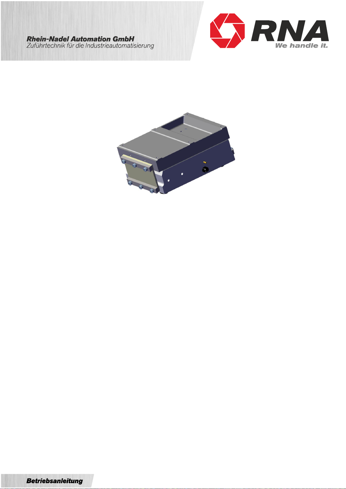
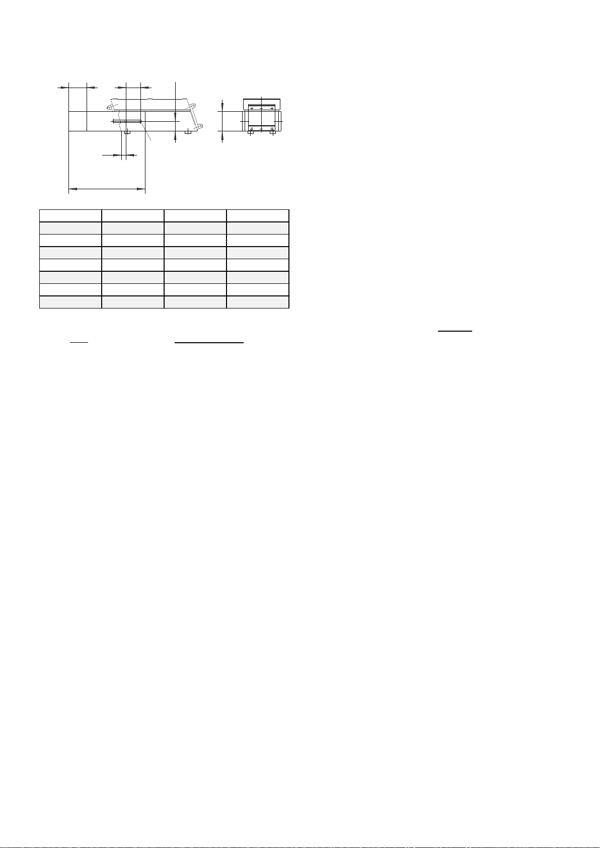
3. Design and functional description of linear feeder
Intended use of linear feeders is the feeding of parts. The driving force is provided by an electromagnetic coil. The
figure below is a schematic representation of a linear feeder:
The linear feeder belongs to the family of vibratory feeders, but produces a straight-line motion. Electromagnetic
oscillations are converted into mechanical vibrations that are used for conveying a material B. When current is applied
to magnet D which is rigidly connected to counter mass F, the magnet exerts a force which attracts and releases
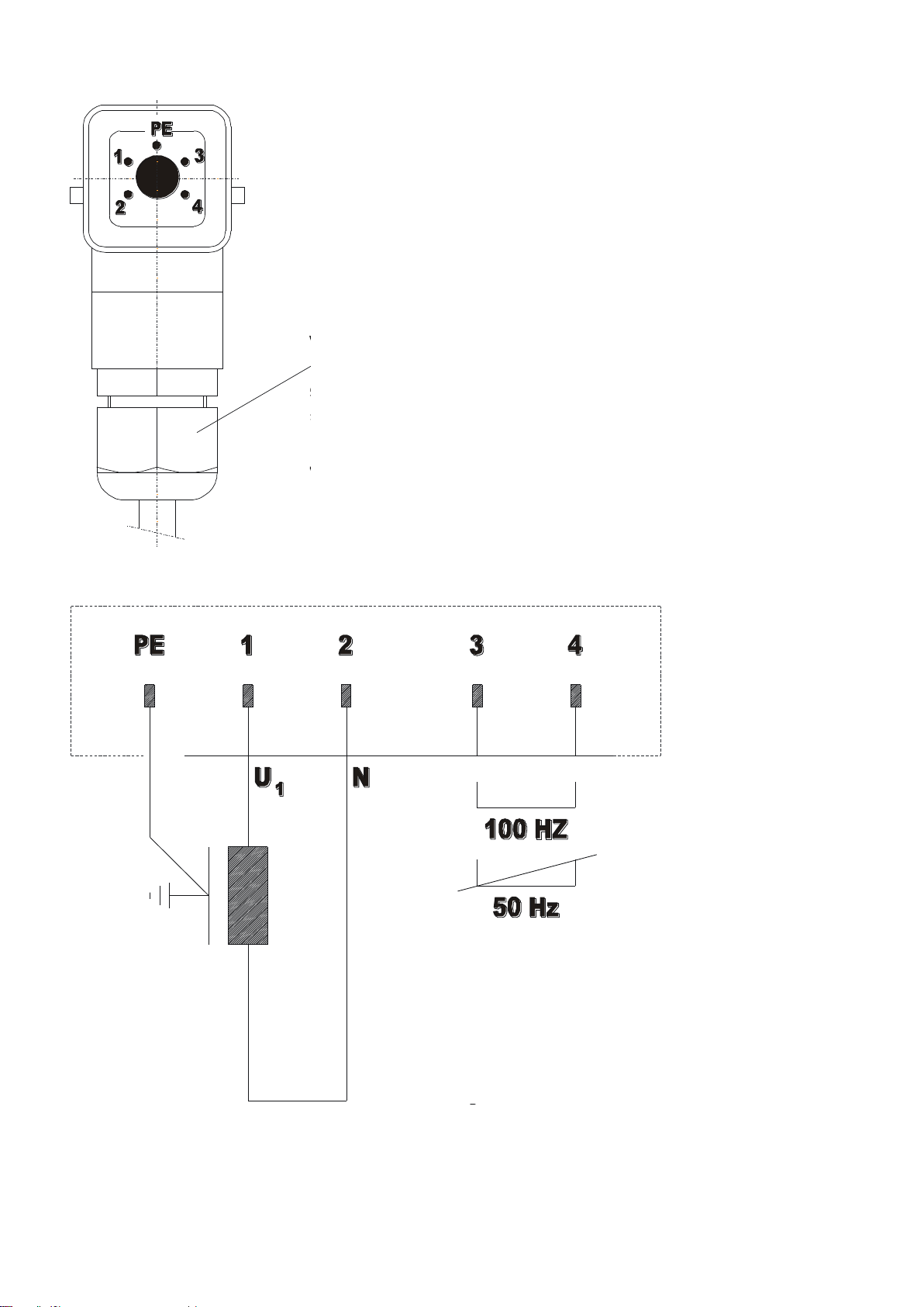
armature E in synchronism with the mains frequency. Within each period of the 50 Hz A.C. mains supply, the magnet
will achieve its maximum power of attraction twice as this force builds up independently of the current flow direction.
Accordingly, the vibration frequency is 100 Hz in this case. If one half-wave is removed, the vibration frequency is 50
Hz. The vibration frequency of your linear feeder is indicated in the 'Technical data' table in Section 1.
A linear feeder is a resonant system (spring-mass system). As a result, its factory set-up will rarely meet your on-site
requirements. Section 5 describes in detail how you can adapt the feeder to your specific requirements.
The linear feeder is controlled by a low-loss electronic control unit (type ESG 2000 or ESG 1000). The linear feeder
control unit is supplied loose (not installed). The controller has a 5-pin connector on its front panel for connection to the
linear feeder.
For assignment of the socket pins refer to the technical data in Section 1.