GALILEI GIANO 70 Operating instructions

USER AND MAINTENANCE MANUAL
Read carefully and keep for future use
GIANO 70 / GIANO 70 VD
R290
GB
ORIGINAL INSTRUCTIONS
AS/NZS

Cod. 80000050b – 23.04.2013
THANK YOU !
Dear customer,
We thank you very much for choos ng a product of Gal le Refr geraz one.
We w sh you a prof table and successful use of th s cab net, meanwh le we k ndly ask you to read
carefully the content of th s manual before ts nstallat on and use. The nstruct ons of th s manual
w ll prov de you all the necessary nformat on to guarantee a safe, effect ve, and long-last ng use
of th s equ pment.
Gal le Refr geraz one’s Team
Caut on!! Read the content of th s manual before nstallat on and
use of the equ pment
Cons der the User Manual as ntegral part of the equ pment.
Ensure that the Manual s at d sposal of the personnel who w ll be us ng the cab net and\or carry ng
out any ma ntenance operat on on t.
In case of resale ensure that the Manual s passed on to the subsequent owners.
Keep the Manual n good cond t ons for the whole l fe of the equ pment, and ensure ts content
rema ns undamaged. In case, ask for a copy to the manufacturer.

Cod. 80000680 – 23.04.2013
FOR YOUR SAFETY
Cabinets working with flammable refrigerant R290 ( ropane)
End-users and service personnel are required to fully
understand and observe the following instructions.
Notice: cabinets working with flammable refrigerant are identified by a specific abe app ied to the
side of the base. The Type of refrigerant is a so specified in the rating p ate, see be ow picture.
Each and every operator, as we as the maintenance personne , must carefu y read und fu y
understand or have these instructions exp ained before using this equipment.
Warning!! Do not damage the refrigerant circuit.
Warning!! Do not keep exp osive substances such as aeroso cans with a f ammab e prope ant
inside the equipment.
Warning!! Do not use mechanica devices or other means to speed up the defrost process un ess
those (if any) express y permitted by the producer.
Warning!! Do not use e ectric app iances inside the disp ay area un ess those (if any) express y
permitted by the producer.
Warning!! Keep c ear of obstruction a venti ation openings in the app iance enc osure
Do not exceed the oad imits of disp ay decks and she ves, as reported in the “Genera Data and
Features” section.

Cod. 80000680 – 23.04.2013
Warning!! In case the cab e or the p ug is damaged, ask for a prompt rep acement by qua ified
maintenance personne .
SERVICING, MAINTENANCE AND REFRIGERANT HANDLING
R290 is c assified as flammable refrigerant of C ass A3 according to ANSI/ASHRAE. It is a high y
f ammab e and very easy to ignite. It can burn with exp osive impacts.
R290 in contact with air can cause a risk of fire or exp osion in presence of open flames or sparks
generated by e ectrica equipment
Servicing can be on y performed by qualified personnel ho ding a va id certificate from an
accredited assessment authority which authorises:
- the competence to work on and break into a R290 refrigeration circuit
- the competence to hand e refrigerants (inc uding hydrocarbons) safe y in accordance with the
EN13313:2011
Service intervention must be carried out considering the mentioned above risk: do not use electric
tools and open flames.
Components which require substitution: on y use original spare parts for they have been
specifica y approved for the use with this kind of refrigerant gas.
The refrigerant circuit is hermetica y sea ed (c osed oop) therefore refrigerant fi ing, draining or
substitution of some components is not possible without breaking the vacuum. In such a case:
- the substitution cannot be performed indoor at the customer’s premises.
- the cabinet shou d be moved to a controlled workshop environment suitab e for the type of
repair where work can be conducted safe y.
- In any case, work in confined spaces must be avoided. Work area can be in the open or,
a ternative y, must be proper y venti ated. Venti ation shou d be ab e to safe y disperse any
re eased refrigerant and expe it externa y to the atmosphere.
Whi e working on cabinet working with R290 during which the refrigerant can be possib y re eased
to the surrounding space, a possib e ignition sources, inc uding cigarette smoking, must be
reasonab y far away from the p ace of insta ation, maintenance or disposa ,
In case hot work is required (we ding, brazing) best practice must be applied. This shou d require
the fo owing procedure to avoid risk of fire or exp osion.
-remove refrigerant
-purge the circuit (with inert gas)
-evacuate
-purge again with inert gas
-open the circuit by cutting (or brazing)
Operator must be proper y ski ed and authorized to perform hot works on systems working with
f ammab e refrigerants.
For Sp it-Systems: In order to reduce f ammabi ity hazards the insta ation of this app iance must
on y be carried out by a suitab y qua ified person.

Cod. 80000060a – 28-01-2014
INDEX
General data and features ………………………………………………………………………… 1
General dimensions 1
Unloading and handling of the cabinet 2
Noise level weights 3
Position of water draining outlet and power connection 3
General recommendations …………………………………………………………………………………….. 5
Placement of the cabinet 5
Electric connections 6
Preserving the displayed products 7
Cleaning 8
Maintenance 9
Safe use of the cabinet 10
Nameplate ……………………………………………………………………………………………………….… 12
SECTION ESE VED TO INSTALLATION
AND MAINTENANCE PE SONNEL
Setting-up and starting the unit ……………………………………………………………………………… 14
Installation of front glasses and endwalls 15
Installation of the air-baffles 16
Assembling and installation of the bumper rails 18
Multiplexing 21
Control panel, parameters table and wiring diagrams .……………………………………… 26
Declaration of conformity (Annexe)………………………………………………………………………..……

1 Cod. 80000070b – 23.04.2013
GENERAL DATA AND FEATURES
GIANO 70 promotional refrigerated cabinet
Self-service refrigerated cabinet with forced air circulation and built-in condensing unit suitable for the
displaying and merchandising of pre-packed food such as salami and cold meats cheese milk and dairy
products delicatessen fruits and vegetables. Complete with endwalls display decks in galvanized steel
powder-coated front bumper-rail in stainless steel D. 20 mm electronic control panel with safety circuit
breaker as main switch evaporator with thermostatic valve automatic defrost automatic system for the
re-evaporation of the defrost water. Base in galvanized steel powder-coated equipped with swivelling
wheels and leveling feet on the front side. Foamed body adjustable both in height and inclination
multiplexable with others on all sides.
General dimen ion
Front View
Giano 70 L: 937
Front View
Giano 70 L:1875
Front View
Giano 70 L: 1250

2 Cod. 80000070b – 23.04.2013
Unloading and handling of the cabinet
in order to be transported the cabinet is delivered on a Europallet with standard dimensions (120 x 80 cm)
and fixed by means of proper fixing plates. Unloading must be carried out by means of a forklift using the
designated handling points for this kind of pallet (along the stringerboards or deckboards see hatched area
on the below pictures). We take this opportunity to remind that the use of forklifts is exclusively allowed to
authorized personnel who has been properly certified as “forklift operator”. During unloading placement
and installation of the cabinets the use of proper protective equipment is required (e.g. protective gloves
and eyeware).
For the placement of the unit on the final point of installation please refer to the section “GENERAL
RECOMMENDATIONS” -> “PLACEMENT OF THE CABINET”.
1
Basement front
-
panel
2
Front levelling feet
3
Rear swivelling wheels with brakes
4
Sliding guides
5
Side bumper
-
rail
6
Endwall
7
Front bumper
-
rail
8
Condenser cladding panel
9
Condensing
unit
1
0
Cable
-
wrap bracket
11
Defrost water tank
12
Control panel
13
Air intake baffle
14
Display decks
15
Fan panel
16
Load limit
mark
17
Evaporator
18
Insulated
carcass
19
Air discharge baffle
20
Sel
f
-
s
ervice front glass
Cross Section

3 Cod. 80000070b – 23.04.2013
Once the cabinet is placed on the final point of installation remove the protecting film and all fixing plates.
The cabinet will look like the above pictures. Endwalls bumper-rails and front-glasses are packaged
separately and placed on the display decks inside the cabinet.
For the installation of the parts mentioned above make reference to the section “SETTING-UP AND
STARTING THE UNIT” of this manual. We remind you that the installation must be carried out by skilled
personnel only assembly instructions are therefore to be found in the section of this manual dedicated to
technical staff (“SECTION RESERVED TO INSTALLATION AND MAINTENANCE PERSONNEL”)
Weight
Giano 937: 125 kg (w/o packaging) 150 kg (with packaging)
Giano 1250: 135 kg (w/o packaging) 160 kg (with packaging)
Giano 1875: 180 kg (w/o packaging) 205 kg (with packaging)
Noi e level
Noise level of the cabinet can vary according to the environment conditions (temperature and humidity
inside the P.o.S.) and to the cleaning level of the condenser. The tests carried out in our lab have recorded a
noise level of 55 dBa (according the conditions defined in the norm EU 89/392/CEE).
Maximum Loading
Maximum Loading for Giano 70 is 90kg/m2 uniformly applied.
Considering the available display surface of both models the overall limits are:
Giano 70 L:937 60kg
Giano 70 L:1250 80kg
Giano 70 L:1875 120kg
Po ition of water draining outlet and power connection
The cabinet is equipped with a built-in condensing unit and an automatic system for the re-evaporation of
the condensing water. In normal conditions (operation in the climate class certified for this model) no floor
water-outlet or additional cable ducts are to be provided; they will have instead to be provided in case of
possible remote versions served by external condensing units.
For this purpose the positions of water draining-outlet evaporator piping opening and cable-exit are
shown in the below picture. Dimensions are referred to the points located on the bottom part of the
injected carcass respect the basement of the cabinet itself. The below dimensions are related to a cabinet
in horizontal position.

4 Cod. 80000070b – 23.04.2013
Water draining outlet (PVC pipe D.40mm)
Evaporator piping opening
Bottom cable-exit
(1) (2) Alternative exits (blind)

5 Cod. 80000080c – 17.07.2018
GENERAL RECOMMENDATIONS
It is hardly necessary to pay attention to the following instructions and guidelines, as well as to the
pictograms and their meanings. The topics included in this section of the manual have been categorized
and grouped according the following criteria:
NOTIC : information for a correct and effective use of the equipment.
DANG R: topics related to potential risks for users and third persons.
WARNING: topics related to potential risks for things and/or for the equipment itself.
Placement of the cabinet
For unloading and handling of the counter by means of a forklift make reference to the handling lifting
points described in this manual. The use of forklifts is exclusively allowed to skilled and authorized
personnel who has been certified as “forklift operator”. During unloading, placement and installation of the
cabinets the use of proper protective equipment is required (e.g. protective gloves and eyeware).
The cabinet cannot be used in open spaces. Verify the environment conditions in which the unit is
going to be installed (temperature and relative humidity) and make sure they are not higher than those of
the climate class indicated in the identification plate (e.g. climate class 3, max. temp. 25°C, R.H. 60%).
Higher levels of temperature and or relative humidity can possibly cause a higher energy consumption and
poorer performances of the cabinet. Such possible conditions are therefore likely to cause a shortening of
the shelf-life and a rapid deterioration of the displayed products.
Avoid the exposure of the cabinet to direct sun ight, or a placement of the unit in proximity of hot
sources like cooking ovens, heating radiators, high-intensity lighting systems and any other possible heating
source.
It is hardly recommended to place the unit away from doors, windows, AC air-grills. In any case, it
must be avoided that air drafts with speed higher than 0.2 m/sec may hit the cabinet.
Cabinets with built-in condensing unit (plug-in): assure a frequent change of air in the environment in
which the cabinet is operating, also during closing time closing holidays of the P.o.S.
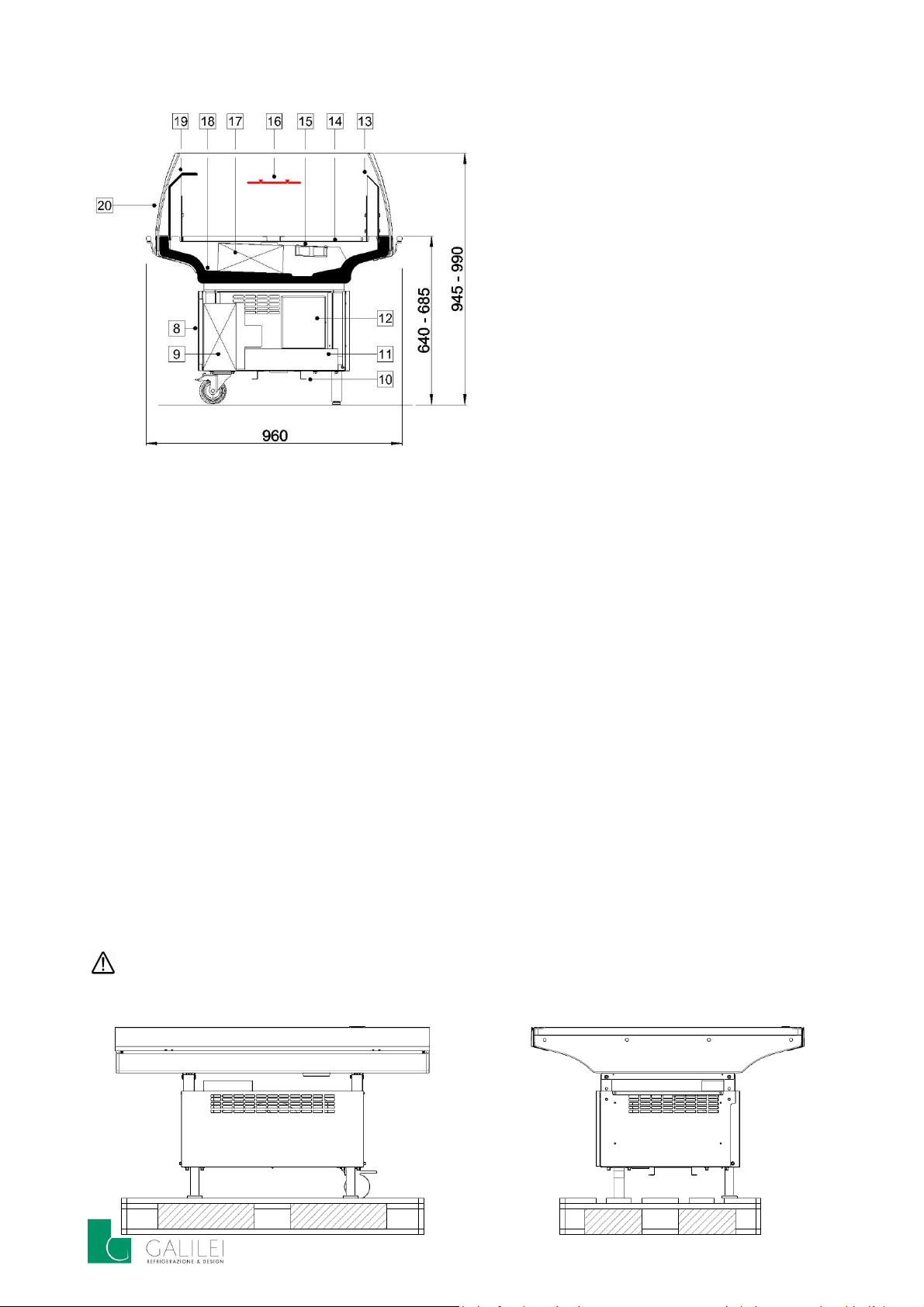
Cabinets with built-in condensing unit (plug-in): the basement of the cabinet has been engineered to
guarantee a proper ventilation of the condensing unit, it is therefore recommended not to obstruct the air-
intake gri s by p acing materia s, of whatever nature, a ong its externa perimeter.
Warning: insta ation of further covers or customized c adding systems of the basement is not a owed.
Cabinets with built-in condensing unit (plug-in): some plug-in units (e.g. promotional stand-alone
units) can be multiplexed side-by-side and or back-to-back, to form larger shop-around-islands. In this case
it is recommended to observe the instructions and the arrangement drawings included in this manual, and
not to exceed the indicated number of multiplexed units. The failure to observe these requirements lead to
a higher energy consumption and, as result of an insufficient ventilation, also to possible damages of the
condensing unit itself.
Cabinets with built-in condensing unit (plug-in): In case the cabinet is placed with its backside to a wall,
make sure to leave at least 5cm between the wall and the backside of the unit.
Once the cabinet is placed in the final point of installation, remove the packaging and the possible
protecting film. For remote counters, remove the handling bars (if present) fixed to the levelling feet.

6 Cod. 80000080c – 17.07.2018
Before operating the cabinet, feet supports must be adjusted so that the unit is stable and perfectly
horizontal. Such condition is necessary to guarantee a proper drainage of the defrost water and a running
of the equipment without vibrations and noises. In case, adjust the levelling feet (if present) checking at the
same time the horizontal alignment with a spirit level, both along the length and the width of the cabinet.
In case of cabinets equipped with tank for the evaporation of the defrost water, check the correct
installation of the tank inside the basement. Check also the correct mounting position of the drain trap and
related piping, and its connection to the drainage outlet of the cabinet.
Before to wire plug the unit to the power supply, it is necessary to clean both the internal and external
surfaces of the cabinet, particularly those of the display decks. For this purpose, it is recommended the use
of simple luke-warm water possibly combined with neutral detergents. Use a soft and non-abrasive cloth
for drying.
Electric connections
The power supply to which the cabinet is going to be connected must have been realized according,
and in keeping with, the regulations and the laws of the country in which the unit is installed. Frequency
and voltage rating of the power supply must correspond to those listed in the identification plate of the
cabinet. Before switching on the power, make sure that the voltage rating matches the one required, within
the allowed limits of ± 10%.
Upstream of the socket it is recommended the installation of an omni-polar power isolator switch,
with air gap between the contacts of at least 3mm. This measure is to be considered mandatory if the
connected load exceeds 1000W, or if the equipment is connected directly to the power supply without the
use of a plug. As power isolator switch it is recommended the use of a proper high-sensitivity differential
circuit breaker.
Connection to a state-of-the-art grounding system is mandatory and necessary to guarantee a safe
use of the equipment.
In order to avoid a hazard due to inadvertent resetting of the thermal cutout, this appliance must not
be supplied through an external switching device, such as a timer, or connected to a circuit that is regularly
switched on and off by the utility.
Cabinets equipped with supply cord: do not use patch cords, power adaptor sockets and multiple
sockets. Do not allow the cable to bend sharply. Avoid that compression, stretching and twisting forces may
damage the cord. Avoid the contact with hot surfaces and sharp edges. In case the cable or the plug is
damaged, ask for a prompt replacement by qualified maintenance personnel.
Cabinets equipped with supply cord: in case the socket does not match the shape of the plug, ask for
the replacement of the socket with a suitable type by qualified personnel. The replacement of the socket
also requires a check of the suitability of the cables (cross-sectional area and length) in respect of the
connected load.
Cabinets equipped with supply cord: before inserting the plug in the socket, make sure that the power
switch (according the model, differential safety circuit breaker or master switch) is in open position (“0”,
OFF, or green position). Insert the plug and then turn the power switch on (“1”, ON or in red position). In
case of long inactivity periods, turn the power switch off (“0”, OFF or in green position) and then pu out
the p ug. Proceed in reverse order to restart the unit.
Cabinets equipped with supply cord: If the supp y cord is damaged, it must be replaced by the
manufacturer, its service agent, or similarly qualified persons or its service agent. Use original spare part
only (Supply cord with Y-Type attachment)

7 Cod. 80000080c – 17.07.2018
Cabinets with remote condensing unit: electric connections and start-up must be carried out
exclusively by qualified technical personnel.
Cord plugs of external devices equipment produced by third parties (e.g. slicing machines, weighing
machines etc.), and or power lines for additional sockets (possibly delivered as accessories), will have to be
connected to separated power ines installed by qualified personnel, properly sized and protected in
respect of the loads to be connected.
Setting-up working parameters: for the adjustment of the “set-point” temperature and the other
working parameters make reference to the instructions of the control panel included in this manual.
Attention!! When setting up the set-point, make sure that the resulting temperature inside the cabinet is
coherent with the temperature class of the cabinet and or with the kind of product to be displayed. Setting
up a too low temperature may cause the evaporator to ice up, compromising a proper circulation of the air
inside the cabinet.
The working temperature of the cabinet is displayed by the digital thermometer installed inside the
cabinet (most commonly in the air-intake grill), and not by the display of the electronic controller. The
readings provided by the electronic controller, or by possible other devices (if present), cannot be
considered as reference to assess the preserving temperature and the performances of the unit. This is due
to the mounting position of the temperature sensors, which are placed according technical criteria related
to the temperature inside the cabinet and not directly related to the product temperature.
Preserving the displayed products
The refrigerated cabinets are designed with the aim to guarantee the displaying and the preserving of
pre-coo ed products. Products must therefore have been previously refrigerated and stored in refrigerated
warehouses or cold-rooms, at a temperature as close as possible to the ideal one. The quality of the
displayed products is strictly related to the effectiveness of the “cold chain” through which they are
processed before the final placement in the cabinet. Products not previous y precoo ed p aced in the
refrigerated cabinet cause a worsening of its performances, with possible damages to the goods already
displayed. It is therefore of fundamental importance to avoid a standing of the products, even temporarily,
in not refrigerated places, since this condition would increase the core temperature of the products. At the
delivery of the products from the supplier, make sure that they are promptly stored in cold rooms or
directly in the cabinet. Meats in particular, must be kept in refrigerated environment throughout the whole
manufacturing process (sectioning, boning, slicing, packaging etc.); if not, and in case the duration of the
process lasts for more than 2 minutes, make sure they are quickly brought back to a coldroom.
For a proper and effective running of the unit, avoid a placement of the product inside the cabinet
which may hinder the correct circulation of the refrigerated air. Furthermore, it is important to observe the
load limit (red line) __▼___▼__. When stacking the products or packages in the cabinets, the stacking
height must not exceed the loading limit. The product exceeding the loading limit would not be properly
refrigerated and that would cause air turbulence with negative effects on the performances of the cabinet
(massive formation of frost inside the evaporator with loss of heat transfer). Such condition would increase
the core temperature of the product, also for the one properly displayed.
It is hardly recommended not to p ace the product on the air-intake gri s (commonly placed close to
the display decks, on the front side of the cabinet). Such condition reduces the refrigerated air-flow inside
the cabinet, and a consequent rise of the product core-temperature.
In order to reduce the loss of cold air as much as possible, drawers doors of the refrigerated cabinets
(if present), doors of multideck counters or cold-rooms, can be kept open only for the time necessary to
perform the loading and unloading of the product.

8 Cod. 80000080c – 17.07.2018
The cabinets are equipped with an automatic system for the cyc ic defrost of the evaporator. This
system is handled by the electronic controller of the control panel. Defrost parameters are pre-set in
factory according the necessities and specificities of each unit. In particular cases it may be necessary to
manually initiate a defrost cycle, by operating the related function of the electronic controller (make
reference to the section of the manual dedicated to the electronic controller). A manual defrost will have to
be activated whenever a loss or a reduction of air flow is detected at the air-discharge grill. Such condition
occurs when the evaporator is clogged by frost, thus hindering a proper circulation of the refrigerated air. A
massive or too fast formation of frost inside the evaporator may require the manual defrost to be activated
with anomalous frequency. This is an indication of improper environment conditions, not suitable for the
use of the cabinet (too high temperature and relative humidity inside the p.o.s.), or a wrong placement of
the product inside the cabinet itself (see previous chapter, “preserving the displayed products”).
During closing time or closing holidays, it is recommended to use the so called “night blinds” or “night
covers”. This measure provides a substantial reduction of the energy consumption, and a better
preservation of the products.
Cleaning
Warning: safety first!! Before starting any c eaning operation, it is MANDATORY to switch-off the
cabinet and to disconnect it from the main power supp y by operating the sectiona ising switch upstream
of the corresponding power ine. (open position in “0”, OFF or green condition). It is recommended to
apply a lockout-tagout procedure (isolation, lock and tag of all energy sources). The Lock and tag of the
isolation points lets others know not to de-isolate the cabinet during the cleaning operation. In case of
plug-in cabinets, switch off the unit and disconnect the plug from the electrical outlet.
Warning: for the cleaning of the cabinet do not use in any case jets or streams of water, water hose or
high-pressure machines. In case, only for the cleaning of the internal part of the carcass, pour lukewarm
water gently inside the carcass from a container. Pay attention not to wet the e ectric parts such as fan
motors, sensors, defrost heaters, thermometers, electronic expansion valves (if present), wiring plugs etc.
The non-observance of these requirements may lead to irreversible damages, and a consequent need of
replacement of the devices mentioned above.
Warning: the evaporator inside the carcass is made up of a tight pack of aluminum fins; the fins
represent, because of their nature, an actual risk of injuries (cuts and abrasions) to hands and arms. On
counters equipped with electric defrost, electric heaters could still be hot even after the cabinets is turned
off (e.g. just after a defrost cycle) with a potential risk of burns. For the above reasons the use of protecting
gloves is hardly recommended.
Warning: hot cabinets for the displaying and merchandising of pre-cooked food are equipped with
infrared lamps, typically installed inside the top canopy. The supporting structure and the lamps itself may
cause serious burns. Before any cleaning operation, let the lamps and any other hot surface cool down
properly.
For the cleaning only use lukewarm water possibly with neutral detergents and, for drying, a clean soft
cloth. Do not use abrasive pads, abrasive or corrosive detergents, thinners, alcohol or solvents of any kind.
Cleaning of the internal parts: frequency of the cleaning depends on the nature of the displayed
product. Cabinets used for the displaying of fresh product such as meat, sausages and dairy products,
require the cleaning on daily basis of all display surfaces (display decks, shelves, air grills etc.), in order to
prevent the growth and developments of bacteria. On weekly basis it is also necessary to clean the internal
bottom surface of the carcass, mostly in those cases in which the displaying cause the product to release
liquids, grease or debris. For low-temperature cabinets (for frozen products) cleaning operations should be
planned on monthly basis.

9 Cod. 80000080c – 17.07.2018
Cleaning of the external parts: a frequent cleaning routine helps to keep the cabinets presentable, to
preserve it for a long-term use and to convey a sense of cleanliness and hygiene to the customers. It is
therefore recommended to clean frequently the external parts of the cabinets, such as glass
superstructure, backshelves, cladding panels, aluminium profiles, etc.
Maintenance
Any Maintenance task, as we as any access to technica parts, are strict y reserved to qua ified and
authorized service personne (refrigeration technicians, e ectricians, etc.). In case, switch-off the cabinet
and disconnect it from the main power supp y by operating the sectiona ising switch upstream of the
corresponding power ine. (open position in “0”, OFF or green condition). It is recommended to apply a
lockout-tagout procedure (isolation, lock and tag of all energy sources). The Lock and tag of the isolation
points lets others know not to de-isolate the cabinet during the maintenance operation. In case of p ug-in
cabinets equipped with chord p ug, switch off the unit and disconnect the p ug from the e ectrica out et.
For cabinets working with f ammab e refrigerant R290 (Propane) see specific safety warnings provided at
the beginning of this manua .
At regular intervals, and at least once a year, the cabinet and its structural and electric components
should be carefully checked by maintenance personnel, (condensing unit if present, controllers and control
panels, thermometers, defrost heaters, fan motors, solenoid valves, etc. ). Check for possible coolant leaks,
as well as water leaks from coupling points (in case of multiplexed cabinets), from the drainage piping and
water taps placed under the carcass. Make sure that the state of maintenance of the electric system
guarantee a correct and safe use.
Cabinets with lift-up front glasses: during loading and unloading of the cabinets, as well as cleaning
and maintenance operations, front glasses must be lifted until they reach the maximum opening position
and kept in this position only for the time strictly necessary to carry out the required operation. In normal
conditions of use frontglasses must remain closed (in lowered position). Gas springs (“pistons”), with which
every glass module is equipped, are an aid for the lifting and a safety measure to prevent the glass to fall
down accidentally. The efficiency and the correct fixing of the gas springs to their supporting structure must
be checked on monthly basis. If the opening of the front glass requires an effort higher than usual, that
means that one or both gas springs are losing their efficiency. In this case have both of them be replaced by
qualified personnel.
Cabinets with built-in condensing unit: in normal conditions of use, the condenser should be cleaned
at least once a month, by using a brush with soft bristles and a vacuum cleaner. A condenser clogged with
dirt causes a higher electric consumption, and an overload of the compressor which may drastically shorten
its service life. The aluminium fins of the condenser represent a risk of injuries to hands and arms, the use
of protective gloves is therefore recommended.
Cabinets equipped with lighting system and fluorescent lamps: before to replace any burn-out lamp,
switch-off the cabinet and disconnect it from the main power supply by operating the sectionalizing switch
upstream of the corresponding power line (open position in “0”, OFF or green condition). In case of plug-in
cabinets, switch off the unit and disconnect the plug from the electrical outlet. Wear protective gloves.
Take the lamp at the two ends and turn it 90° until a slight click is heard, then remove it being careful not to
knock it against anything. Remove the transparent plastic protection from the lamp (“sleeve”) and keep it
for the new lamp. Apply the protection to the new lamp and fit the assembly following the above
procedure in the reverse order.

10 Cod. 80000080c – 17.07.2018
Safe use of the cabinet
This appliance cannot be used by people, including young children, whose physical, sensorial or
mental capacities are reduced, or by people who are not properly trained unless they are supervised by a
person responsible for their safety.
Young children should be supervised to ensure that they do not play with the appliance
Unsuitable use of the unit, or part of it, is strictly forbidden.
Using the cabinet, avoid overloading of display decks, shelves and top canopy and observe the loading
limits declared in this manual (see section “General Data and Features”). Do not place product or any other
object over the front glasses unless the superstructure is provided with supporting stanchions (valid for
serve-over cabinets).
Note for p ug-in unit running on R290 (Propane): see specific safety warnings provided at the beginning
of this manua .
Dismantling and disposal
For the preservation of the environment, all parts and materials composing this counter have to be
sorted in accordance with the waste disposal regulations in force in the country where the disposal occurs.
These parts cannot be considered in any case as common household waste. In particular, the components
of the refrigerating circuit must not be dismantled separately, and proper measure must be taken to
prevent a release of refrigerant gas in the environment.
The dismantling of the refrigerating circuit must be carried out by authorized center, specialized in
recycling of refrigerant gases.
Note for p ug-in unit running on R404A – R134A: The cabinet contains fluorinated green-house gasses
covered by the Kyoto protocol.
Note for p ug-in unit running on R290 (Propane): see specific safety warnings provided at the beginning
of this manua . The operator must be properly skilled and authorized to handle equipment working with
f ammab e gas, in a contro ed workshop environment where work can be conducted safe y.
After the safe removal of refrigerant, the system should be flushed with OFN (Oxygen Free Nitrogen) to
render the unit safe. The process should be repeated several times until satisfied that no R290 is still within
the system.

11 Cod. 80000080c – 17.07.2018

12 Cod. 80000090c – 20.07.201
NAMEPLATE
The nameplate is normally placed beside the control panel, or inside the counter in case of multideck
or island unit. The plate contains all the necessary information to identify the unit, and the technical
specifications for its correct installation and functionin .
The cabinet is subject to WEEE Europena Directive 2002
/96/EC (only for plu
-
in cabinets)
RoHS
The cabinet is compliant with RoHS European Directive 2002/95/EC
(only for plu
-
in cabinets)
If present, it indicates the cabinet has IMQ certificate
22
2
1
2
0
19
18
17
16
15
14
13
12
11
10
9
8
7
6
5
4
3
2
2
1

13 Cod. 80000090c – 20.07.201
Meanin of the ratin plate fields
1 Model name, with len th in centimeters and possible additional marks identifyin a iven version
Attention: this infor ation ust always be provided when requiring any spare-part
2 Serial number, code and/or confi uration number (if present)
Attention: this infor ation ust always be provided when requiring any spare-part
3 Year of manufacture
4 Climatic class, indicatin the proper environment conditions in which the unit operates correctly.
3 – the unit is suitable for operatin in an ambient with temperature of 25°C and a relative humidity of 60%
4 – the unit is suitable for operatin in an ambient with temperature of 30°C and a relative humidity of 55%
5 Temperature class of the unit, indicatin the cate ory of products that can be displayed and preserved in the cabinet:
L1: suitable for the preservation of frozen food or ice-creams
M1: suitable for the preservation of fresh products such as meat and poultry
M2: suitable for the preservation of fresh products such as salamis, sausa es, dairy products
H: suitable for the preservation of fresh products such as fruits and ve etables
S: suitable for preservation of products with special classification
6 Maximum power absorbed by the unit, with the required optional installed, operatin in the temperature class for which
the unit has been built (see point 5)
7 Power absorbed durin the defrost; includes the electric heater (if present) and all the other electric devices operatin
durin the defrost cycle, such as controllers, fan motors, li htin etc.
8 Rated supply volta e, number of phases and frequency to which the cabinet must operate. Before installation, check that
the data on the ratin plate is compatible with mains power supply.
9 Electrical power absorbed, rated volta e and current of other electric devices installed (e. . automatic re-evaporation of
the defrost water, hot cases, automatic ni ht blinds, etc.)
10 Electrical power absorbed, rated volta e and current of the defrost heaters (if present)
11 Electrical power absorbed, rated volta e and current of the demistin heaters (if present)
12 Type and quantity of refri erant used
13 Indicates the kind of lamination device.
CT = capillary tube
TVX = thermostatic valve
14 Net volume of the additional refri erated stora e (if present)
15 Refri erated display area available for displayin the oods
16 Maximum operatin pressure inside the refri eration circuit of the unit
17 Rated electrical power absorbed by the unit in normal operatin conditions
18 Rated electrical power absorbed by the unit at the compressor startin phase (startin current)
19 Kind of condensin unit or compressor installed
20 Electrical power absorbed, rated volta e and current of the li htin system (if present)
21 Electrical power absorbed, rated volta e and current of the fan motors (if present)
22 Electrical power absorbed, rated volta e and current of the condensin unit (if present)

Cod.
TECHNICAL SECTION
!

15 Cod. 80000410a – 02.12.2014
INSTALLATION AND START-UP
Installation of the front glasses
Front glasses are kept in their mounting position by longitudinal slots made on the top side of the front
fa ias. On e removed the pa kaging of the glasses and the prote tive films, insert the lower rim of ea h
glass inside the slots, gently pressing downwards until they rea h the bottom of their respe tive slots. The
glasses are identi al and geometri ally symmetri al. For the installation of the glass It is therefore not
ne essary to onsider a spe ifi rim of insertion.
Glasses are tempered and have hamfered and deburred edges, nevertheless the use of prote ting
gloves is required for any installation, maintenan e and leaning operation.
Installation of the endwalls
The endwalls are made of a ryli glass, with a thi kness of 20mm. On the lower side of ea h endwall, 4
slotted holes are present for the fixing to the inje ted body; on this latter, orrespondent threaded inserts
are already on pla e. For the fastening, use the M6 s rews provided. It is re ommended the use of a
manual s rewdriver, and not ele tri or pneumati s rewdrivers, sin e a possible over-torquing an ause
irreparable damages to the endwalls and/or to the inje ted body. By doing so, he k the mounting position
so that the shapes of endwalls and front glasses mat h together. In ase, loosen the s rew slightly to fine
adjust the position of the endwall.
On e the endwalls have been fixed to the body of the abinet, remove the prote tive films from both their
internal and external surfa es.
This manual suits for next models
1
Table of contents
Other GALILEI Refrigerator manuals