2
PRECAUCIONES DE SEGURIDAD
.- Pantalla olor de 4,3".TFT c
.
- Monitor manos libres.
- .Pulsadores de función y selección de funciones del menú
- Pulsadores de acceso rápido (monitor en reposo).
.
.
- Entrada pulsador de puerta de la entrada del rellano"HZ" . Hasta 6 monitores/viviendas
con el pulsador "HZ" activado al mismo tiempo (con el sistema y los monitores en reposo).
Importante:
- Menú de instalador.
.
- Menú de ajustes pantalla y volumen.
- Menú de usuario.
- Salida sonería auxiliar (máximo 50mA/12V).
.
.
- Microinterruptores .de configuración
- Led de estado.
- Monitor con instalación simplificada (bus de 2 hilos no polarizados).
- Pulsadores de activación abrepuertas 1 y 2.
.
.
.
.
.
- No apretar excesivamente los tornillos de la regleta.
- Siga en todo momento las instrucciones de este manual.
- La instalación y manipulación de estos equipos deben ser realizado por personal autorizado.
.
- Cuando se instale o modifique el equipo, hacerlo sin alimentación.
- Toda la instalación debe viajar al menos a 40 cm. de cualquier otra instalación.
- Instale el monitor en un lugar seco y protegido sin riesgo de goteo o proyecciones de agua.
- Evite emplazamientos cercanos a fuentes de calor, húmedos, polvorientos o con mucho humo.
-Antes de conectar el equipo, verificar el conexionado entre placa, alimentador, distribuidores y monitores.
CARACTERÍSTICAS
FUNCIONAMIENTO DEL SISTEMA
*
( )
*
( ) Para más información ver manual de usuario “TART 4/G2+ (cód. 50122527)”.
https://doc.golmar.es/search/manual/50122527
3
DESCRIPCIÓN DEL MONITOR
Configuración dirección (código) del monitor:
*
( )
*
( ) Para más información ver manual de usuario “TART 4/G2+ (cód. 50122527)”.
https://doc.golmar.es/search/manual/50122527
INSTALACIÓN DEL MONITOR
*
( )
Edificio / Chalet (Placa Nexa)
*
( )
ESES
MONITOR 4ART /G2+MONITOR 4ART /G2+
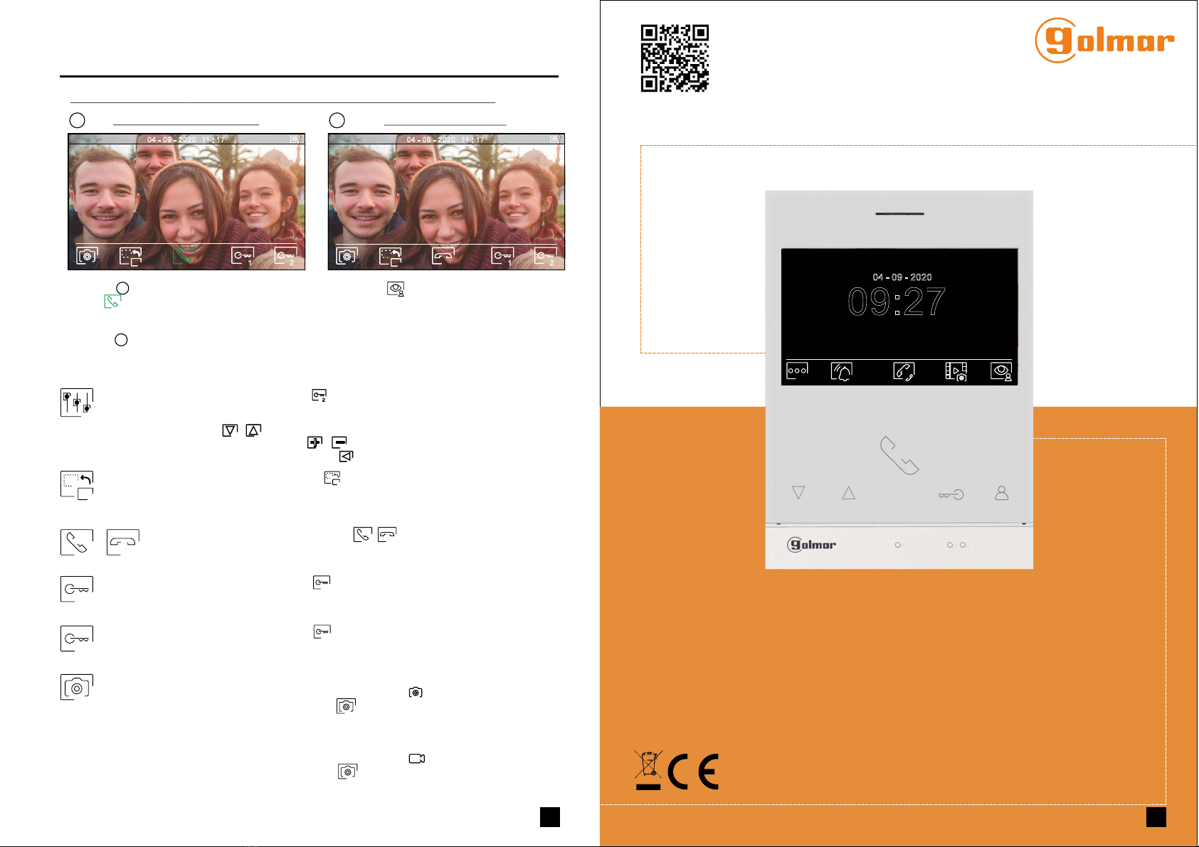
- La comunicación tendrá una duración de . o hasta resionar sobre el pulsador situado debajo d90 seg p el
icono colgado en el monitorde . Finalizada la comunicación, el led de la placa se apagará y el
canal quedará libre. Si la síntesis de voz está habilitada, el mensaje “llamada finalizada”nos indicará en
la placa que la llamada ha finalizado.
.
- Si se desea abrir la puerta , resione sobre el pulsador situado debajo del icono correspondiente
que se muestra en pantalla durante los procesos de llamada o comunicación: una sola pulsación activa
el abrepuertas durante segundos, el led de la placa se iluminará también durante seg. Si la
síntesis de voz está habilitada, el mensaje “puerta abierta”nos será indicado en la placa.
ó p
3 3
- Para la descripción de funcionamiento y configuración del monitor, ver el manual del monitor.
.
.
- Para realizar la llamada, el visitante deberá presionar el pulsador correspondiente a la vivienda con la
que desea establecer comunicación; un tono acústico advertirá de que la llamada se está realizando
y el led de la placa se iluminará. Si la síntesis de voz está habilitada el mensaje “llamando”nos
indicará que la llamada se está realizando. En ese instante, el monitor de la vivienda recibe la
llamada. Si se ha presionado por equivocación el pulsador de otra vivienda, pulsar sobre el que
corresponda de la vivienda deseada, cancelando así la primera llamada.
- Al recibir la llamada, la imagen aparecerá en la pantalla del monitor principal (y secundario 1, caso de
existir) sin que el visitante lo perciba y el icono mostrado en pantalla parpadeará en color verde.
Si se desea visualizar la imagen desde los monitores 2 ó 3, presione sobre uno de los pulsadores
del monitor de
la placa el canal quedará libre.
para que aparezca la imagen. Si la llamada no es atendida antes de 45 seg., el led
se apagará y
.
.
- Para establecer comunicación, presione el pulsador situado debajo del icono de descolgado .
mostrado en pantalla. El led se apagará y el led de la placa se iluminará.
12
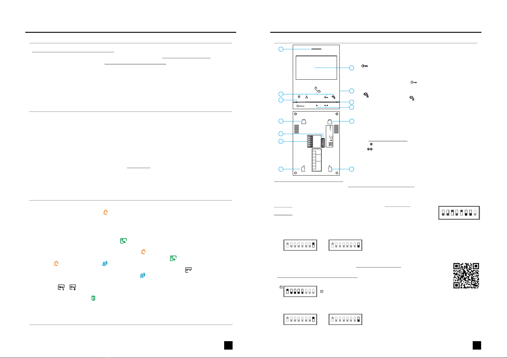
A. Altavoz.
G. SD (no incluida).Ranura tarjeta micro
B. Pulsadores de función, acceso y selección de funciones del menú.
- Con el código especial '0441' (Apertura automática de puerta) ya
introducido en el monitor (ver
), presione el pulsador durante 5 seg. para activar/
desactivar la función.
códigos especiales en manual
“TART 4/G2+”
- El led del pulsador parpadeará color blanco si la función
(Apertura automática de puerta) está activada y se apagará si
la función está desactivada.
Amarillo fijo: En reposo sin notificación.
D. Pantalla TFT color 4,3".
E. Micrófono.
Rojo fijo: Modo "No molesten" activado.
En llamada :/ comunicación
Sobre este punto de orientación está el pulsador de "Inicio/ fin
comunicación".
La función de cada pulsador, es mostrado en la pantalla del
monitor con un icono situado justo arriba de cada pulsador (ver
).manual “TART 4/G2+”
Pulsador de acceso rápido (monitor en reposo):
Pulsador de acceso rápido (monitor en reposo):
- El led del pulsador parpadeará color blanco, indicando foto/
video pendiente de visualizar. Al pulsar accederá al menú de
grabaciones.
C. Led de estado monitor:
F. invidentes.Puntos de orientación para personas
Sobre este punto de orientación está el pulsador "Apertura de puerta".de
Tipo: MicroSD Clase 10 de 4Gb hasta 128Gb.
H. Anclaje regleta de fijación a pared (x4).
J. Terminales de instalación.
I. Interruptores de configuración.
*
Chalet (Placa SOUL)
Dip1 a Dip :7 Asigna la dirección del monitor al pulsador de llamada de la placa.
Los interruptores a 7 deben permanecer en la posición .2 OFF
123
ON
4 5 6 7 8
Vivienda 1
Vivienda 1 (Dip1 a ON) monitor ART G2+ con V.0 y posterior.4/ 3
*
4Kit Soul / Art
Manual
1
( )
1
( )
*
*
A
D
B
C
E
H
I
J
H
H
H
SA
GND
HZ
HZ
ON
1 2 3 4 5 6 7 8
BUS
F
BUS
G
Dip1 a Dip :7 Configurar la dirección del monitor (dirección 1 a 2 ).1 8
Dip8: Configura el final de línea. Dejar en ON en aquellos monitores en los que acabe el recorrido del cable de
Bus. Resto colocar en OFF.
Los interruptores colocados en la posición OFF tienen valor cero. En la posición ON tienen asignados los valores
de la tabla adjunta. El código del monitor será igual a la suma de valores de los interruptores colocados en ON.
123
ON
Ejemplo: 0 + 0+4+0+16+ = 200+0
Interruptor nº: 1 2 3 4 5
Valor en ON: 1 2 4 8 16
6 7
32 64
Tabla de valores
4 5 6 7 8
Importante:
Vivienda 1 (Dip1 a ON y Dip2-Dip7 a OFF)
123
ON
4 5 6 7 8
Dip 8 a ON
1 2 3
ON
4 5 6 7 8
Dip 8 a OFF
Vivienda 128 (Dip1 - Dip7 a OFF).
(”0551" Secundario “0552" “0553" )."0550" Principal, 1, secundario 2 ó secundario 3
Nota: Para definir el monitor como principal o secundario, onfigure el código especial correspondientec :
Dip8: Configura el final de línea. Dejar en ON en aquel monitor en l que acabe el recorrido del cable de .
Resto colocar en OFF.
e Bus
123
ON
4 5 6 7 8
Dip 8 a ON
1 2 3
ON
4 5 6 7 8
Dip 8 a OFF
Nota: Para definir el monitor como principal o secundario, onfigure el código especial correspondientec :
(”0551" Secundario “0552" “0553" )."0550" Principal, 1, secundario 2 ó secundario 3
12210430 V05ProductVersion:
MONITOR 4.3”ART 4/G2+
GOLMARS.A. C/ Silici, 13 08940-SPAIN
WARNING
Toprevent fire or electric shock, do not
exposethis device to rain or moisture
Toprevent electric shock, do not remove cover.
CAUTION
Nouser serviceable parts inside.
Referservicing to qualified service personnel
MADEIN CHINA
128
codes
SA
OFF = 0
ON = 1
DIP 1 to 7
DIP 8
Monitor
address
EOL
resistor
GND
HZ
HZ
BUS
BUS
128
codes