Gamebox GGDH User manual

Installation &
Assembly Guide
For VA1 models or any Dual ASIC Game Gear
A PRODUCT OF Gamebox LLC ©2023
EXPERT
(Document Revision 10) 3.24.23

Is a product of Gamebox Systems LLC.
https://www.gamebox.systems
Our Socials
Instagram
instagram.com/gamebox.systems
instagram.com/postmanmods
instagram.com/nobble64
discord.gg/9ctaU
Join the community
™
Twitter
@GameboxSystems
@PostmanMods
@Nobblesnozzles

Kit Contents:
• GGHD PCB
• Genesis controller PCB
• 9 pin FFC ex cable
• 4x 25mm M3 screws
• 4x 4mm M2 screws
• Capacitor replacement kit
• Case parts (Top, middle spacer bracket, bottom, power button plunger)
Tools Required:
• Soldering iron
• Solder (Lead free or leaded)
• Phillips size 0 or 1 screwdriver
• Gamebit security screwdriver
• Wire (30AWG – 34AWG, single or multistrand)
• Needle nose pliers
• Desolder tool (Solder pump or copper braid)
• Tooth brush/Q-tip (Optional / Recommended)
• Isopropyl Alcohol, 90% (Optional / recommended)
Parts Required:
• VA1 or Dual ASIC Game Gear*
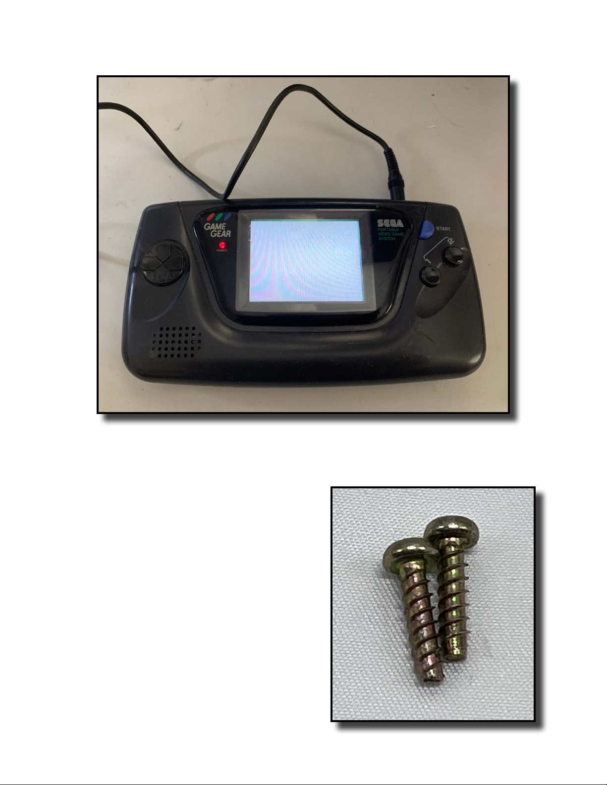
* 2 M3X11 philips screws if your system is missing the cartridge slot screws.
Page 3
Gamebox LLC can, in no way, be held liable for any damage to the user’s property, or the user’s health from
following these instructions. While these instructions aim to give the user a comprehensive and safe guide to
completing this modifcation, there are many potential variables that could result in the unit that the user is at-
tempting to modify requiring more restorative measures. ere is also a serious risk of, injuries, and death when
working with electronics. At the time of this guide’s writing these consoles are rapidly aging, and even working
units should be recapped as soon as possible. Chemicals associated with some of these processes are quite toxic
and should be handled with care and adult supervision. Results may vary. “GGHD”, “Gamebox”, “Gamebox Sys-
tems”, “gamebox.systems”, its associated internet domains, and the associated logos in this document are trade-
marks(™) of Gamebox LLC , A Limited Liability Company. is document, text and, images contained there-in are
property of Gamebox LLC ©2023 Gamebox LLC, all rights reserved.
Legal Disclaimer

Remove the 6 phillips screws and 1 gamebit screw holding the two halfs of the shell together and
carefully open up the Game Gear.
Page 4
PART 1: Game Gear Recap & Functionality Test
STEP 1

PART 1: Game Gear Recap & Functionality Test
STEP 2
Page 5
Ensure your Game Gear is compatible with this modication by nding a silkscreen that says “VA1”
when you open the case. If you see “VA1”, continue to step 3. All Dual ASIC models of Game Gear are
compatible with this mod.
NOTE: If you are not using a Dual ASIC board or DO NOT see “VA1” and you see “VA4”, “VA5”, or do
not see “VA1” then your Game Gear is NOT COMPATIBLE with this version of the hardware. A further
hardware revision will include support for these later models.

PART 1: Game Gear Recap & Functionality Test
STEP 3
NOTE: If a recap has been performed and the system is veried 100% working, skip step 3 and move
ahead to STEP 5 of PART 1.
Page 6
Remove cables from power and audio PCBs. Use a tooth brush or Q-tip with isopropyl alcohol or deoxit
to clean any corrosion o the Game Gear motherboard. Once the corrosion is cleaned, use needle nose pliers to
grab and GENTLY move the capacitors back and forth to break the glue underneath each capacitor

PART 1: Game Gear Recap & Functionality Test
STEP 3(continued)
Page 7
Remove all capacitors on the back of the motherboard and replace all capacitors on the motherboard and
the power PCB. For a capacitor map, go to https://wiki.console5.com/wiki/Game_Gear
Find your motherboard and power board revisions and follow the diagrams to recap your PCBs. Audio PCB
does not need a recap.

PART 1: Game Gear Recap & Functionality Test
STEP 4
Page 8
Reconnect the power PCB to the motherboard and close the Game Gear. Connect a power source (wall
adapter or 6x AA batteries), plug in a game, and test the console. Ensure the console powers on and reads the
game. If the recap is successful, move on to STEP 5.
NOTE: Save the screws from the cartridge
connector shown(right). Otherwise you will have to
procure 2 new M3X11mm screws. ey are required
for nal assembly.

PART 2: Game Gear Motherboard Preparation
STEP 5(a) For Dual ASIC Models
Page 9
Remove the circled componants.

PART 2: Game Gear Motherboard Preparation
STEP 5(b) For Single ASIC Models
Remove the circled componants.
Page 10

Page 11
PART 2: Game Gear Motherboard Preparation
STEP 5(c) For Single ASIC Models
Remove resistor R56

Remove the reective shield. Desolder the points in the red circles and remove the CFL tube and the
fuses.
NOTE: Solder must be removed for the GGHD to sit at on the motherboard.
PART 2: Game Gear Motherboard Preparation
STEP 6
Page 12

Remove tape below the cartridge connector. Remove the screen from the motherboard by applying
GENTLE but rm pressure upward and drag soldering the screen pin contacts. e screen cable will li cleanly
from the contacts one at a time when drag soldering with correct pressure applied. Remove excess solder from
screen pins on the motherboard.
PART 2: Game Gear Motherboard Preparation
STEP 7
Page 13

When doing a SINGLE ASIC installation replace each of the circled resistors with 4 solder bridges. Dual
ASIC installations can ignore this step.
PART 2: Game Gear Motherboard Preparation
STEP 8(For Single ASIC Install)
Page 14

Place the GGHD PCB on the Game Gear motherboard aligning the cartridge 16 connector pins to the
solder holes on GGHD as shown. Slide GGHD down as far as possible to make the castellated edges as close as
possible to the screen pins on the Game Gear motherboard. Ensure Pin 9 aligns with the rst castellated edge.
PART 3: GGHD PCB Installation
STEP 9
1 9
Page 15

FIRST Solder to the cartridge pins as shown. Apply a small amount of donward pressure on the GGHD
PCB to ensure it is as close as possible to the Game Gear motherboard. Only the solder pins on the cartidge con-
nector that are soldered in the picture above are required.
THEN Solder the castellated edges to the screen pins on the Game Gear motherboard by soldering at the
the point where the two PCBs meet.
PART 3: GGHD PCB Installation
STEP 10
Before moving to step 11, take a moment to ensure the GGHD PCB is sitting as close as possible to the
Game Gear motherboard. If there are any gaps caused by excess solder on the screen connector pins or the solder
points shown in step 6, remove the solder before continuing.
Failure to follow step 10 may result in a botched install!
STEP 11
SOLDER FIRST
SOLDER SECOND
Page 16

Solder to the anchor points circled. Apply a generous amount of solder rst, then pinch the 2 PCBS
together while applying the soldering iron to the anchor points again to ensure the PCBs are as close as possible.
PART 3: GGHD PCB Installation
STEP 12
Page 17

Solder GG Clock to either resistor pad circled in red.
NOTE: Keep this particular wire as short as possible! A long wire may cause graphical artifacting.
PART 4: Wiring Controls And Sense Signals To GGHD
STEP 13(a) For Dual ASIC Models
NOTE: Unless specied, pad labels on the Game Gear motherbaord are the same on Single and
Dual ASIC Motherboards. Location may vary slightly.
Page 18

Solder “GG Clock” to either of the points circled in red.
NOTE: If graphical artifacting or distortions occur then refer to the troubleshooting section at the end of
this document about adjusting the length of this wire.
PART 4: Wiring Controls And Sense Signals To GGHD
STEP 13(b) For Single ASIC Models
NOTE: Unless specied, pad labels on the Game Gear motherbaord are the same on Single and
Dual ASIC Motherboards. Location may vary slightly.
Page 19

T10 Location
PART 4: Wiring Controls And Sense Signals To GGHD
STEP 14(a) For Dual ASIC Models
Page 20
Table of contents
Other Gamebox Game Console manuals