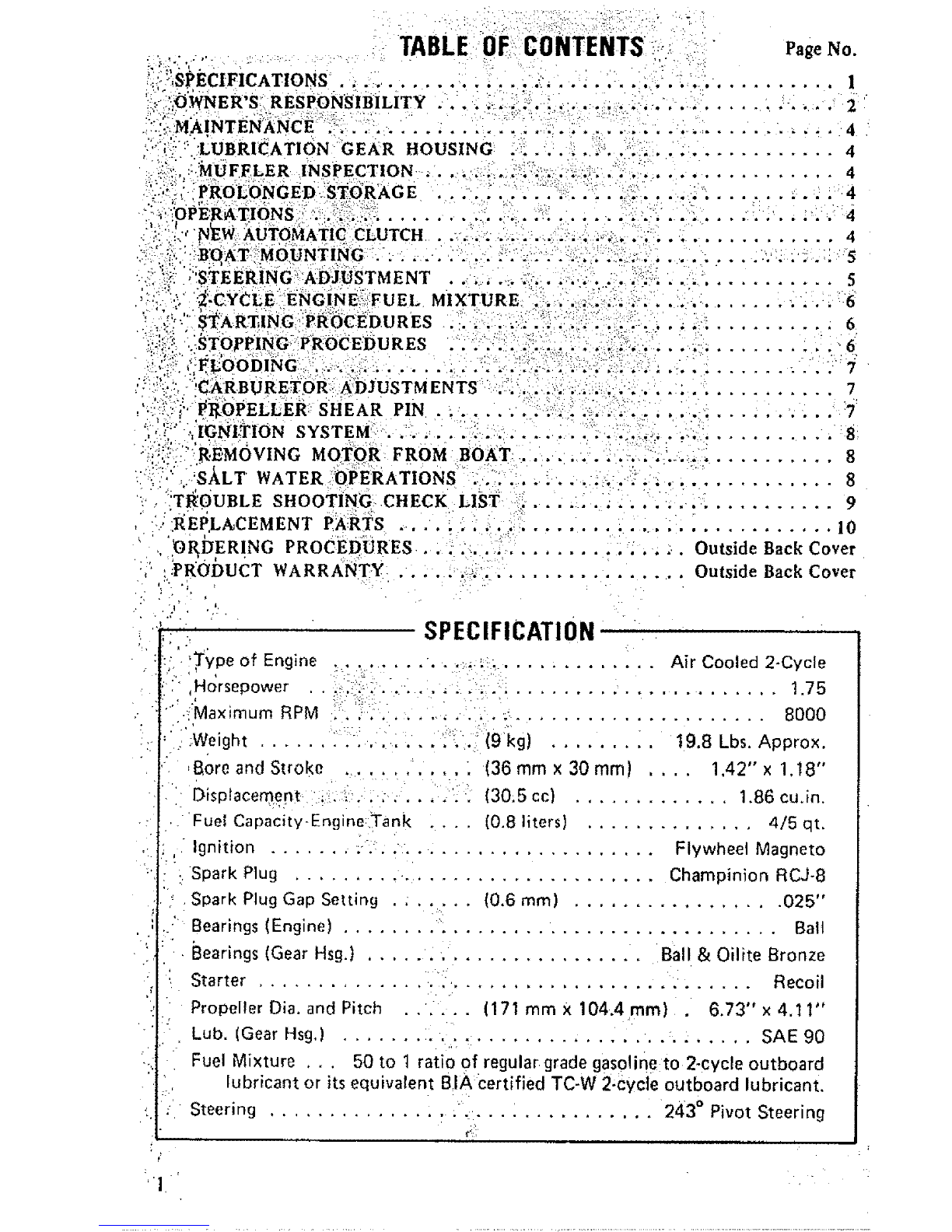
Gamefisher 298.585180 User manual

MODEL NO. .
298:585180
• owner's,
responsibility•
• mainlenance
Di}ouble.....
Shooting" ."
D replacemenl
paMs.....
!,! .
L
i ¸ . •
'bhcoIion No
0-3.5306-203

i:ii::i2:;:I_UBRICATION GEAR HOUSING :i: ..... _'. ,'................. 4
ii_:iii'il::.:MUFFLER INSPECTION ,.._ 1:::_i,!_::_:_ ,_ ;:; ,_;!,:_, ,,............. 4
_:}.:ii__ IPRoL!ONGED II:ST6RAG E , ,, 2_:..:./:_:•:i:_:: .::_. ::r :_ _ _ " . . :'4"_ ...... _ . :_ 4
:i::•I_OP_R_TI6NSi_::i_:i_:_:!iii:!'::_i;..i ...i _:.L.._,: ..... ii::?. :_.... :.:., .'.:. 4
:" '_I,"_N_EW,AUTO_ATi_ CLUTCH • ,!...._.-_' ;_:,_. _:i._:.. _.. ...... 4
;::,:_.,. mXTURE .... . ........... 6
•_:{'?;_.: JRETOR,: :A:DJUSTM EN TS :;/i ::.: i ::!_::;i_:!;:: :-: . 7
SHEAR PIN ............. .iz,_: _.::. :.. , ............ 7
SYSTEM ........ _;, .............. :.?. - ,-. ........... 8
MOTOR FROM BOAT ............ ., ' .......... 8
"::{:" WATER OPERATIONS .... °' 21}122:i_'ii!121;.iii1211111 8
,;':TI_0UBLE SHOOTING CHECK LIST, 9
•iil_EPLACEMENT PARTS 10
.'DI_IERING PROCEDURES ..... • .Outside Back Cover
• _ IPt_Oi)uCT WARRANTY .......................... Outside Back Cover
i SPECIFICATION
1]
-:/ 'lype_'- of Engine " ...... -.............. Air Cooled 2-Cycle
Horsepower . .,:. : .......... .......................... 1.75
Maximum RPM .. ,.. ................................ 8000
• ,:';Weight "(9kg) !9.8 Lbs, Approx,
,Bore and Stroke " (36 mm x 30 mm) .... 1,42" x 1.18"
Displacement ..... :. ...... (30.5 cc) ............. 1.86 cu.in,
• " Fuel Capacity-Engine:Tank .... [0.8 liters) .............. 4/5 qt,
Ignition "Flywheet Magneto
- , Spark Plug .......... ..................... Champinion RCJ-8
Spark Plug Gap Setting .; ..... (0.6 mm) ................. 025"
Bearings (Engine) .................................... Ball
Bearings (Gear Hsg.) ........................ Ball & Oilite Bronze
Starter ......................................... Recoil
Propeller Dia, and Pitch ...... (171 mm x 104.4 ram) 6.73" x 4.I 1"
Lub. (Gear Hsg,) .................................. SAE 90
Fuel Mixture ... 50 to t ratio of regular grade gasoline to 2-cycle outboard
lubricant or its equivalent BIA certified TC-W 2-cycle outboard lubricant.
Steering ................ "................ 243 ° Pivot Steering

IMPORTANT ...... -'..........
Owner's Responsibility and, Operating Safety Check List
:"'_I3E SURE TO READ AND DO THE FOLLOWING, BEFORE
OPERATINGIYOUR OUTBOARD MOTOR : .
,,
.; ! =
SAFETY CHECK LIST _-
1. Learn and observe the b0atingtaWsdf:the U.S, Coast Guard, state, local author,
ities, i....... i ' :
•2. U.S. Coast Guard regu ations t;eqUire thel following: ' :
e, Provide 8n 8pproved Iife,Veitiwpe I, 2 or 3 Personal Flotation Device for cacti
persoh }n bolat, :?(Encourage passengers to wear them.) ....
b, If the boat exceeds;i16 feeti also carry atype 4, throwable Personal Flotation
Device, '.... :::: " :
3, Do not fill fuel tank with motor running or near any flame or lighted smoking
material,
;: 41 When loading boat distribute the load evenly, keep the toad _ow; don't overload;
don't stand in a small boat, Tal_e weather and water conditions into account.
: 5, {3o not permit persons to ride on pelts of the boat not designed for such use,
Standing, bow riding and seat back or gunwale riding can be especially dangerous.
OWNER'S RESPONSIBILITY
:6, Reed owner's manuel before tut_nJi_gyour new outboard molor.
7. Before starting, make sure your motor is securely mounted to boat transom with a
safety chain, Tighten clamp stud handles securely by hand.
8. Be sure to have pliers, screwdriveri _pare spark plugs, wrench, shear pins and cotter
:::: ; :,= pins in boat whenever leaving shore.., ii.......
9, Be sure {o have an adequate supply of fuel (carry only in an approved container) on
board. Use a good grade of regurar gasoline with proper mixture, as cited in the
Specifications, :
0, Occasionally check to be sure clamp stU d handles on transom mounting bracket are
tight.
11. 1N CASE OF AN EMERGENCY, THE ENGINE CAN BE'STOPPED BY DEPRES-
SING THE STOP BUTTON OR PLACING CHOKE KNOB IN FULL CHOKE
POSITION.
12. Keep an alert lookout. Serious accidents have resulted from failure to use eyes,
13. Keel ?fireflghting and lifesaving equipment in good condition and readit _ accessible
'at atl times;
14..Good housekeeping is even more important afloat than ashore, Cleanliness dimin-
:ishes the pt'obability of fire and tripping hazards,
TIPS FOR TRAILERING OR AUXILIARY USE
15. When :launching or loading:boat on a trailer, Place y'our outboard motor _in the
]tilted Stoi-age position. Also when trailering your boat and 0utbo_rd motor, keep
! outb0ard motor in upright (vertical) position on the boat transom, Outboard
Imotors: transported across rough roads in the "tilt" position couldcause ti'ansom
!damage or mounting brackets to break off ,{osingybu.r motor: if motor must be
. trailered in "tilt'* position, a short length of 2 x;4 should be placed between the
l,,:-.;_::;:,_,:'-motor bracket and the motor leg, The motor leg should then be firmly tied down
i:egainst :1;he 2x 4 to prevent any possible damage. Similar precautiens should be
taket_ If using the motor as an auxiliary power sou¢c'e for a sailboat or Power boat.
!:when us_r_g motor as an auxiliary power source, the Use of an auxiliary adjustable
,_;pbsition motor bracket is recommended.

.-MAJOR-,PARTS
ChokeLever
Power Head
FuelFillerCap
andAirVentScrew
SparkPlug
Oua]Au!omaticClutch Housing
Reverse Driving Lock
Fuel Sediment Bowl
and,Filter
Till Pie;Adjuslmenl
MufflerPipe
Exhaust Oulie!
Propeller
Culler Pin
Stop Buflon
Fuel Shut-oil Valve
Throltin ControlLover
• TransomBracket
DriveShaftPipe
Cavilali0nPlale
Fill andDrainPIu_
Bear Housing
GearHousingCovel
Figure i
.•MAINTENANCE
7._' FEATURE .INFORMATION
'_ "This out_)oarrJ mnto_ h;_s special desi,_n
ll.qlltJ_l_S JI_, _hOW!l In |e_JtttJJ 1*
b: Your selection of our Marine Products will
,Provide you with many flours of enjoyable
boating, To assure your complete satisfac-
''"tr_OnOn the investment You have just made,
-, We _sk you to read this manual thoroughly
,'before going afloat. Acquaint yourself with
:.':'lh'e 'particular areas of operation on your
.: '" :,outboard mot0r aS you read the step-by-step
'_ pK6cedureS: Keep in mind maximum per,
-" 46rmarlce is'achieved only when the owner
,q_- oPerator is completely familiar with the
..op_rating instructions•
;c: ,,Per,i'odic servicing wilt be required. It is
_recommended that ,/ou consult your Sears
., SeryiCe _enter when service is necessary.
! We' wilt be happy to extend our facilities
'_snd assure prompt service.
.
PRO
PROPELLER
Figure 2
Figure 3
=.
AND
DRAIN PLUG
GEAR HOUSING
COVER

MAINTENANCE
2. LUBRICATION_GEAR HOUSING
a. The Gear Housing has been pre-lubricated al
the factory; h0wevec ihe grease level should
be checked as follows using SAE 90 out-
board motor grease, (See Figure 2).
11) Prioi" to initial operation;
_ (2) After first four {4) hOurs of use.
13) Recheck after every flfty _t6Ol hou,s
il; 'running time.
(4) Replace with new lubricant at the end
of your outboard motor season. This
is important, as it removes any water
from the gear housing and prevents
possible corrosion to internal parts,
(3} The outboard motor shoutd L
mounted on a stand vertically wit
power head up for storage,
(4) Pull starter handle si0wly until resis
ance ;s felt due to compression pre
sure, ther, stop. Release starter tensio
srowly tO prevent englne frorr; rever_
pressurL, i 'This t_osition will close bet
the intake and exhaust ports IC
storage.
(5) Drain and fill gear housing as outline
under Lubrication of Gear Hous_n:g,
(6) Wipe exterior completely with ires
b. To Check, Drain or Fill gear housing, foUow , water cloth and then apply light coa"
these steps:
{1) Position outboard motor upright,
(2) Remove drain plug and washec then
insert nozzle of gear lubricant tube
into hole.
(3); Squeeze tube until lubricant is forced
out around tube.
(4) Replace plug and washer. Be sure plug
is tightened securely,
(5) To achieve complete drainage of lubri-
cant, remb;,/e cotter pin, propeller and
shear pin from propeller shaft, also,
gear housing covet by unscrewing 2
bolts.
(6) When lubricant has completely drained,
replace parts and refill gear housing
using f_ll_ng procedure above•
For best results, lubricate propeller .shaft
with Hthium grease every 30 to 60 days,
_ •
3. MUFFLER INSPECTION
a, Periodically remove _ufflor cover by un-
screwing screws and inspect- for car_on
build-up inside the muffler inlet and outlet,
the exhaust port and= the combustion
chamber of the cylinder, Excessive carbon
witl prevent drawing the maximum power
out of the engine. (See Figure 3).
b, Care should be exercised while cleaning
awav carbon to prevent-scratches to the
surface of the engine components and dro_-
ping carbo_ inside of crankcase.
:ing of oil,
b+ When starting a new season, always use fres
gasoline, Last year's gasoline may hay
varnish deposits that will plug the carl_.
refer jets, thus requiring a complete ove_
haul,
c. To plan for the coming season; we recorr
mend you contact ,,,our Sears Serv.c
Center before the new season for any servJc
repair work required.
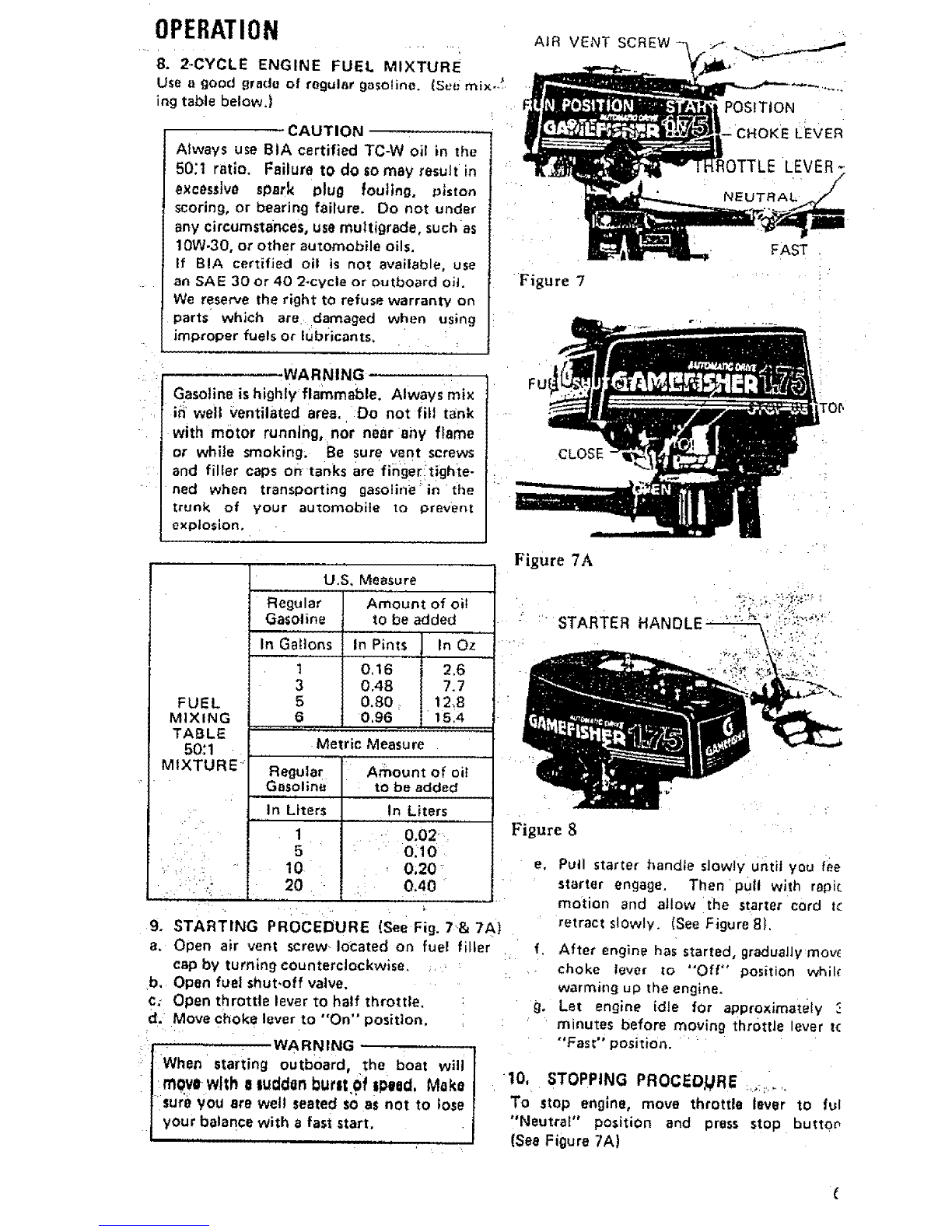
OPERATION
5.
a,
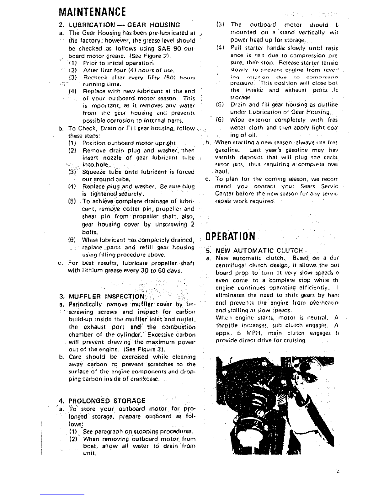
NEW AUTOMATIC CLUTCH
New automatic clutch. Based on a du_
centrifugal clutch des=gn, it altows the out
board prop to turn at very slow speeds o
even come to acomplete stop while th
engine contimJes operating efficiently, I
eliminates the need to shift gears by han_
and prevents tl_e engine from overheatin,
and stalling at slow speeds.
When engine slarls, molar msneutral. A
throttle increases, sub c_ulch engages. A
appx, 6 MPH. main clutch engages t=
provide direct drive for cruising,
4°
a.
PROLONGED STORAGE
To store your outboard motor for pro-
longed storage, ;_repare outboard as fol-
lows:
(1) See paragraph on stopping procedures.
(2) When removing outboard motor from
boat, allow all water to drain from
unit.

OPERATION
6._BOAT MOUNTING
a, ,"Mount the motor on the center of the boat
transom (stern)• (See Figure 4).
• " . CAUTION
Hand tighten clamp larackeI clamp stud
,handJes simultaneously. Oo not use a
',wrench or any other device that would
" cable damage to brackets. OccaslonaIly
"bheck to be sure lamp stud handles on
_.trabsom mounting bracket are light.
, {See Figure 5).
b,' TO ohtnin the best perfnrmane.n from Voter
outboard, the following boat trm_som speci-
•.ficaX ons are recommended: (See Figure 4).
T r.ahsom Angle (See View 3):
.,,,'" ', . ;........... 12 to !5degrees
..Transom Height (See View 4):
", " '; i 20_7 inches
e, T'he angle of the motor column is easily
':..adjusted by removing the Hitch Pin and
'-,changing the Tilt Lock Bracket Pin in the
-three (3), dlf_erent angle position holes
located on either side of the rigttt or left
Trat_som Mounting Brackets. Each angle
ipos_l;i'on: elevates five [5} degrees. Try
c;ehtef hole position first, (See Figure 6)
d'.'_.T6', f_!n_t the correct angle position,'make a
'"t_t':run at full throttle with yOU r u_ual
'. tbadin'g in the boat. Always stop motor to
• .,c_bnge the Tilt Lock Bracket Pin. The cor-
'_,rect,'ahgle position will have your boat
, _-"traVe]Ing with the bow slightly h!gher than
'_th#',s'tern but should not porpoise (bow
._, _rises-'and falls rapidly and continuously). Be
• ._urte._t t Lock Bracket Pin is always pushed
",; cbmpIptely through both Transom Mount-
." ;.ihg'B?ackets and Hitch Pin is secured,
,• ", './, , WARNING
(f'the _no{or column is tilted too far Out-
warld,, the boat is likely to porpoise or
cav_iate at full throttle, which can be
dan'qer6us because across wind or awave
coul_ suddenly- deft'act the boat into a
.da69erous turn. Also, if the' motor
c'olbmn is tilted too farinwatd,.the bow
oY the boat will dig in, which can be
dang_,rous when: crossing, awake "or, in
/[0ugh. Water. Do not run mot0r,in'the
(See View and 2,'st_Srage posltlon. ,1
Figur04]. ,
e:.S_cure motor toboat with Safety Chain.
.. Chain not included witl_ motor,
J
Figure 4View 4
20,7-
Figure 5
TRANSOM BRACKET
CLAMP STUD HANDLES
STEERING TENSION
SCREW
Figure 6
TILT LOCK 8RACKET PiN
AND HITCH PIN
7. STEERING ADJUSTMENT : _ ::
Tighten steering tension screw using ascrew-
dr'}ver for desired steerlng effort. (See Plgure 6),
CAUTION
Ihere is a possibility of losing screw ifbacked out too far.

OPERATION
8, 2-CYCLE ENGINE FUEL MIXTURE
Use agood grade of regular gasoline. {See mix-,_
ing table below.]
CAUTION
Always use BIA certified TC-W oil in the
50:1 ratio. Failure tO do so may result in
excessive spark Plug fouling, piston
scoring, or bearing failure. Do not under
any circumstances, use multigrade, such as
10W-30, or other automobile oils.
If BIA certified oil is not available, use
an SAE 30 or 40 2*cycle or outboard oil.
We reserve the right to refuse warranty on
parts which are damaged when using
improper fuels or lubricants.
-WARNING
Gasoline is highly flammable. Always mix
in well ventilated area. Do not fill tank
with motor running, nor near any flame
or while smoking. Be sure vent screws
and filler caps on tanks are finger tighte-
ned when transporting gasoline in the
trunk of your automobile to prevent
explosion,
FUEL
MIXING
TABLE
50:1
MIXTURE
• • )i ii
U.S, Measure
Regular Amount of oil
Gasoline to be added
In Gallons In Pints In Oz
10.16 2.6
3 0.48 7,7
5 0.80 : 12.8
6 0,96 15,4
,,_, ,, ....
Metric Measu re
Regular Amount of oil
Gasoline :to be added
in Liters
.... 0.02,
: " 0_10
,0;20
:0.40
In Liters
1
5
10• •
2O
9, STARTING PROCEDURE (see Fig. 7,& 7 A)
a, Open air vent screw: located on fuel filter
cap by turning counterclockwise.
b. Open fuel shut,off valve.
c: Open throttle lever to half throttle, :
d. Move chok_= lever to *'On" position.
,, : WARNING
[When starting outboard, the boat will
i ! movewith _1luddan but=tOfIpeed, Make
(sur_ you are well seated so as not to use
J your balance with afast start,
POSITION
LEVER
IOTTLE LEVER-
Figure 7
FAST
FU
CLOSE
Figure 8
e, Pull starter handle slowly u6tit you fee
starter engage, Then pull with rapi¢
motion and allow the starter cord tc
retract slowly. (See Figure 8).
f. After engine has started, gradually move
• choke lever to "Off" position whik
warming up the engine.
g. Let engine idle for approximately
' minutes before moving throttle lever tc
"Fast" position, '
"!0, STOPPING PROCED;URE ......,.....
To stop engine, move throttle lever to ful
"Neutral" position and press Stop buttor
(See Figure 7A)

+ +..* • . , j
j}PEnXTI •
,' :ON: •
WARNING
, ']n-lca'se of an Emergency, th e engine:can
" +be s,topped by moving the Choke Lever to
i :FuI.I Choke POsition. , . - :
•:if'. t_'e motor will not be operated for a
'i .t_eriod 'of time, if it is to be removed from
"1 .the .boat, or if it is to:be tilted up, we
,_+i']• rec_)mmend+the following practice to
"! J!,tsr_;ent spiltage fro m -the carburetor
'"I th'roat and bowl arid to :.prevent gum
/:fo_'tnations in the carburetor during
• / sl'orage: '"
I I, Close h++,,l sht+l-ofl valve and air
l,vent screw at lueI tillel cap.
I 2." Allow motor to run at i'_Jling speed
J : until it stops of its own accord,
{"indicating the carburetor has run
:dry,
1_ _LOODING
Tb clear eng ne of excess fuel, move choke lever
to "Off'_ position and throttle lever to half
throttle position. Pull recoil starter handle
unti} engine starts and conlimies to run.
12. CARBURETOR ADJUSTMENTS
a. Y_)LJ_ +nole, f has _ z(tle iHliustincl screw and
(h_ id{_ S|)eCd hag _)el_l_ l)irl'._lt| a_ the laclory,
However, you may need to adjust the idle
speed using Idle Ad,iusting Screw. Turn the
Screw clockwise to incFease motor speed
and counter clockwise to decrease it. The
idle speed adjustment must: be done with
:_hl-ottle lever at full closed position and the
idle speed should be as low as possible while
the engine runs steady. (See Figure9) I
b: Periodically check filter for dirt by unscrew-
in'g Sediment Bowl,
_3, PROPELLER SHEAR PIN & CHAIN
HOLDER
a.+ The Shear Pin is used for the purpose of
protecting the Drive Train and Gears, The
Shear Pin will not prevent the propeller .....
fi-om becoming damaged when striking an,
under water object. When shear pin i_
• broken the engine wilt contihue to run,'
. ,however, the propeller will not be rotating.
'_.'-"_" CAUTION l
.'l:St0p engine immediately after shearing
_ 1+p_in+tO' avoid possible damage 1;othe engine.
-b_ T,(?: replace shear pin, shut off motor, '
''remove cotter pin with pliers and slip off
,.:_ prQl_eller. (See Figures 10 & 11 ).
._€., Replace with new sheer pin located in Shear
,+' .pin,'and cotter pin holder, (See Figure:t2).
i
Figure 9
Figure 10
Figure 1 1
Idle ASjusting Screw
Figure 12
Figure 13
CONTACT POINT$_
CoNTACT-BREAKER AND _+_
+,+°GLoo+oo°o+
CONTAq%BREAKER _.'_:_]_._/
BASE PLATE "--'----"'_"

OPERATION i i
14, FLYWHEEL MAGNETO IGNITION
SYSTEM
a, The magneto ignition system consists of the
following component parts: Con-tact Points,
Condenser, and Ignition Coil. (See Figure
13),
b, Inspect the following if engine fails or is
hard to start:
(1} Spark plug as often as necessary, Be
sure spark plug gap setting is ,025"
(0.6ram).
(2) Gasoline fuel suPplY and fuel shut-
off valve should be open.
(3) Carburetor being starved of fuel.
c. The correct spark plug for this motor is
Champion RCJ-8.
d, To test ignition system, remove spark
plug and place against bare sPOt on metal
part of motor away from cylinder spark
ptug hole end then pull =_arter cord sovoral
times, if aspark bridges the plug gap, the
magneto is in good operating condition.
The high tension lead wire must be con .=
nected to the plug for this check. If there.
is no spark, have the ignition checked at
your Sears Service Center.
15. REMOVING MOTOR FROM BOAT
a, Always tilt motor by lifting on rear of
shroud. DO NOTPUSH DOWN ON THE
STEERING HANDLE, When removing the
motor from the boat ra se the outboard in
d_rect=on until the propeller _ars
upward
the transom. Hold the motor upright I(_ng
enough to allow all water to drain from the
exhaust pipe. When you find it difficult to
hold the motor upright, tighten the Center
Bolt increasingly for desired effort• (See
Figure 14).
WARNING
Although the engine is air cooled, it is
possible to burn your hands on the engine
biock and upper portion of the column,
Do not touch.
.... C,.
/
''4..
C_TERBOLT \_4_
1
Figure 14
Figure 14A WARNING
If the motor witl not be operated for a
period of time, if it is to be removed
from the boat, or if it is to be tilted up,
we recommend the following practice to
prevent spillage from the Carburetor
throat and bowl and to prevent gum
formations in the carburetor during
storage:
t. Close fuel shut-off valve and air vent
screw at fuet filler cap,
2. Allow motor to run at idling speed
until it stops of its own accord, indb
caring the carburetor has run dry:
d,
it may be necessary to rotate the motor to
one side before tilting the motor on the
transom to remove leg from the water when
16. SALT WATER OPERATION
To materially increase the life of all exposed
parts and decorative finishes, follow the steps
indicated below.
a. Always tilt your motor out of the water
when not in use.
b. Never-leave the lower unit in salt water
0vernigh t,
c. Wipe exterior completely with fresh water
cloth and then apply light coating of oil,
d. Lubricate propeller shaft occasionafly with
a waterproof type of lubricant ILithium
Grease}, thus enabling the Propeller to be
removed easiiy.
e. It is good practice when operating in salt
installed on boats with thick ttansoms_ _ ! water to inspect your motor daily and t.o
Always carry outboard with the engine ,apply a light coating of grease to any
above the lower unit to prevent: moisture .... part or area that shows evidence of car-
from entering the engine through the rosJon Or rust,
exhaust ports, f. Always remove motor from boat ver-
Steering handle serves as carrying handle as tically, allowing wafer to drain from column
shown in Figure 14A, before tilting the motor.
8

TROUBLE SHOOTING CHECK LIST
• Take your Outboard motor into any one of over
2000 Sears Service Unit=.
X __X --__
× X
XX XX
X X X
"X X _ X X
X X X X
X" X X X X
X×X X ×
x X ., •
x x x x x
-X' ×XXX:
XXX X
,,× X
Fuel Tank Empty
Fuel Shut-Oil Valve Closed
Fuet Line Kinked or Pinched
Fuel Filter Dirty of Clogged
Vent Screw on FUel Tank Filter Cap Closed ....
r,_atbur_Iof Passages Ctugged of D,rly
IncorreCt Fuel,Oil Mixture
Carburei0i Out of Adju_iment
Engine Flooded .
Wrong Type S_ad< Plu_ ...............
Defective or Fouled spark Plug
Breaker Contact, Points oUt ,o,,!,Adjus,tment
Defective Magneto .
!
i"
$
iX. '! ........ : s_0,_odesNotJumps_arkP(ugGap
_:i ; X ! EnginoOutofTim_ ........ :,:'::':"=(......
1,_ x x
•x :_ x
:×. x x
.X, X
.............. X"
X
X
X
'* X'.-
''l:'" ',:_i:, IMPORTANT INFORMATION
,:I."M:0oELNUMSER:gB,68S 80
:.,,l,SERIAlL•:, ,.l, NUMBER _ . .
:: f "- -J,-".'' ,. INSUREYOUR ENGINE '
• '1" Many' insurance companies including Allstate
'"11 insq_:ance offer protection contracts for your
f.:b'.Oa,t" _nd outboard engine. Insurance covering
• f" .¥ou:t. own ,equipment against damage, theft,
_'I_: et¢i _a$ wetl as liability insurance for property
:" l:!:: damaoe _nd personal Injury to others Is avatlo-
:I'" hie', _,lf'wouii:l be wise to contact your insurance
"'-] _ent;for further information about adequate
X Breaker Contact Points Burned or Pitted
XWeak Ignition Coil ' "
X Weak or Defective Condensen
.... Spark Plug Lead Wir'e Not Secured " '
•Frayed or Cracked Lead Wire'lnsulation
D'isconnected, Grounded or Loose Wiring in Electrical System
X i "Propellet" Bound by ForeignObjects (Fishing Line. Weeds. Etc.)
High Tension Lead-Salt Water Build Up - " ' "
IDENTIFICATION PLATE
L
NO, HRS. USED
OPERATING LOG
OALS. FUEL USED DATE NO. HRS, USED GALS, FUEL USED

_REPLACEMENT _PARTS
' FOR
...... MODEL::No.298.585180

0
a
1_ _" _"
iv..;
7op'
m
Z
m
Z
m
80
81 I
4
27

FIG. I ENGINE •
REF. No.
1-1
1-2
1-31.
t, 4
1,5
1-6
i.1.8 :i i
1-9
....1-10
" t-ll
1-12
t-13
t-t4
1.15
1-16
1,17
1-18
1-19
1-20
1.24
t-25 =:
1-26 - '
1-27 ,
t-28
t -29
1-30
1.31
1"32
1,33
1-34
1-44
1.45
1-46
1-51
1-52 .:.
i _-55
t-65
1-66
!.67
1-68
!-69
1-70
1-74
1-75
1-76
1-77
1-78
1-79
1-80
PART No.
016-0t046-200
157-04000-900
0t8,00562-200
:002,01046-800
017"O 1000" _O3 _ r:
040-0t000-201 !
041-01000-201,
039-01000-200
031-0100D,200 ._ _.
037,01000.200 i.
046-01003-804
068-02000-200:
._ PART NAME
CYLINDER SHROUD
SPARK PLUG ASS'Y
SPARK PLUG RCJ.8
CYLINDER COMP
CYLINDER GASKET
PISTON RING/TOP
PISTON RING/LOWER
CIR CLIP
PISTON ''
P{STON PtN
CRANK SHAFT COMP
WOOD, RUFF KEY 3 x13 x 5
070-0240t-20t
999-6!620-200
999-66152-500
076-01000.212
999-62101-004
177-20701-801
173-01046-800
159.20701-900
071.02007,200
071.02007,210
071.02007-220
071-02007-230
071-02007-240
999-61620-200
:999-66t52-500
'090-01000-200
076,0t000-212:
203-01000-201
167-20753-800
19_01046-900
155"20750.800
112.01048-200
202-01003-201:
246.20701"201
247-01000-201 .
19,1,01046-200
999-67045-000
::;173-2070i-802_"
256-01046-200
990-11050-102
992.10050-O41
990-11050-382
992-10O50-042
990-11040-081
994.15040-101
990-11050-202
992-10050-042
065-00000-200
066-00000-200
990-11050-202
992.10050.042
992-10060-042
CRANK SHAFT WASHER
BALL BEARING #6202
OIL SEAL 15257
CRANK CASE MAG SIDE COMP
NEEDLE BEARING #t0t0
CONDENSER COMP
PRIMARY coRD
CONTACT BREAKER ASS'Y
CRANK SHAFT SHIM 13,05
rCRANK SHAFT SHIM 0,10
CRANK SHAFT SHIM 0,15 ":
CRANK SHAFT SHIM 0.20
CRANK SHAFT SH[M 0.30
8ALL BEARING .#6202 i: .: i:
OIL SEAL '#15257 - ' _-
CRANK CASE GASKET .... "
CRANK CASE DRIVE SiDE
PRIMARY CORD GROMMET
IGNITION COIL COMP
CORD SUPPORT ASS'Y
MAGNETO ROTOR COMP
FAN CASE
SECONDARY CORD GROMMET
MAGNETO CAM
CAM SUPPORT SPRING
POINT COVER
O-RING G-45 _ - ,
PRIMARY CORD
SPARK PLUG RUBBER COVER 8'
SCREW 5 x 10
WASHER 5
SCREW 5 x 38 '
S. WASHER 5
SCREW 4 x 6
SCREW 4 x 101P,S
SCREW 5 x 20
S. WASHER 5
FLYWHEEL WASHER
FLYWHEEL NUT
SCREW 5 x20
S. WASHER 5
S. WASHER 6
Q'ty
I
I
1
1
I
I
I
2
I
1
I
2
I
I
I
I
I
1
I
I
I
I
I
I
I
I
I
I
I
I
I
I
I
2
I
I
I
1
I
I
4
4
4
4
I
2
2
2
I
I
4
4
4
12

150
BO •
Q
11'I

FIG.1 ENGINE
,REF. No. PART No, NAME C}'ty
1-8t
1-91
1-92
1-93
1.94
1-95
' 1-96 _
1-150
991-0t060-021
992-10040-012
99f-01030,Oll
992-10030-012
992-01030-011
990-11040-t02
992-10040-042
985-35306-900
P/kRT
NUT 6
S. WASHER 4
NUT 3
S. WASHER 3
WASHER 3
SCREW 4 x 10
S- WASHER 4
ToOL _KiT_,-
I
= ....... .
•'•r :
H
]
r. '_ •i::::
4
1
1
1
3
3
1
]4

61
60
44 43 42
66 48
_i63
51
49
1 \
I03_ \
t2
Z

FIG.2
REF.- No.
TANK, CLUTCH &MUFFLER
PART No. PART NAME
2. 1
2-2
2,3
2-4
2-5
2-6
2-7
= _ 2.8
2-9
2-I0
2.11
2-12,
2.13
2,14
2,15
2-16
2.17
2q8
_' 2-19
2-20
2-31
• : ,2-22
''2-23
-2-24 395,01225-200'
•2-25 394-01202-201
"': : -2-26 3gg-01000_200
"2-27 390-01046.200
_, 2.28 455-22907-90t '
2-29 424-10201-200,
'2-30:'_.-_ ! 437-10201-200,
"_2-31 333.01046-200 '
2-32 347,01046-200
2-33 210-35300-800
2.34 358.10112.200
2-35 290.10112-802
2-36 .359.10112-203
2-37 I 357-10112,204
2.38 342.10112-202
2-39 ..... 992-01080-011
RECOIL STARTER ASS'Y
TANK CAP ASS'Y
ENGINE COVER
TANK SUPPORT RING
TANK
STARTER PAWL SPRING
WASHER 5
STARTER PAWL
STARTER PAWL SHIM
STEp BOLT
COCK HOLDING METAL
'COCK ASS'Y :
"COCK NUT
STOP BUTTON
STOP -BUTTON COVER
SPECIAL SPRrNG WASHER
STOP BUTTON FIXING NUT
PIN HOLDER ,, ::: _''
FUEL PIPE :':
FUEL PIPE '_: :
756,00537,900
595-35100-902
300-35306-200
600-35100-203
40t-35300-200
790-00B01-202
992-01050-011
788.00601"203-
822,00601-200
793.10200-200
662-01046-200
592-10201-900
594-00517-200
170-01046,800
266.00503.202
18t-01004-200
1B0-01004-200"i "
021-35100-201
700,14508-068
700-14508-050
680,01004-200
701-00817-200 i
398-01000-202 :,
:.LEAD VALVE ........
LEAD VALVE COLLAR
LEAD VALVE SEAT
CARBURETOR ASS'Y
' CLEANER CAP
CLEANER JOINT
CLUTCH HOLDING BASE
CLUTCH FLANGE .....
CLUTCH'SPR NG:COMP "
CLUTCH WASHER A
CLUTCH ARM coMP
CLUTCH WASHE,R B
CLUTCH STEP BOLT
CLUTCH SPRING
CLIP _8 .: :
FUEL PIPE STOPPER .....
LEAD VALVE SEAT GASKET
LEAD HOLDING METAL
WASHER
2-40
2-41
2.42
2-43
2-44
2.45
2-46
2-47
2-48
2-49
2-50
2-51
2-52
2-53
2-54
991-0t080-011 NUT 8
737-01000-20t MUFFLER
715-01046-200 MUFFLER
737-01046-200
717.01046-200 _
22!.35500-200
226-35500-200
220.35300.200 '_
225-35500-200
227-35500-200
990-11040-252
992-10040-042
990-11060-162
992-10060-042
990.11030-101
GASKET
BODY A:.: ":
....... MUFFLER GASKET ii: :
MUFFLER BODY B :, ::
MUFFLER PiPE GASKET " " ....
MUFFLER PiPE STAY A
MUFFLER PIPE
MUFFLER PiPE STAy .-
MUFFLER PIPE STAY B .....
SCREW 4 x 25
S. WASHER 4
SCREW 6 x 16
S. WASHER 6
SCREW 3 x 10
k• •
Q'ty
ft
1
t
1
2
2
2
2
2
1
!
1
1
t
1
1
l
'3
1
t.
I
2
t
1
1
1
t
1
3
3
3
3
3
3
t
t
1
1
1
!
1
1
1
I
3
3
3
3
2

61 62
60 _
44 43 42

FIG.2
REF, No.
2-55
2-56
2-57
2-58
2-59
2"60
2-61
2-62
2-63
2-64
2-65
2-66
2.67
2-68
2-69
2-70
2-71
2,72
2.73
2-100
2-101
2-102
2-103
TANK, CLUTCH & MUFFLER ._
._ ,,,,
:PART" NQ_ PART NAME
,.t,, , - ....
990-1 I040-162 :
992-104;)40-042
990- !1040-302
992-10040-042
990-11040-t22
902.10040-042
990, ! 1060-202
992-10060,042
990-11050-122
992-10050-042
990-I 1060-252
992-10060-042:
990-11050-122
992-1O05O-042
992-01050-041
990- ! 1060-122
992- t 0060-042
012-35500,200
011-35100.200
330-35306-200
331-35306-200
906-35306.200
336,35118-200
SCREW 4_x 16
_S. WASHER 4
SCREW 4x30
'S. 'WASHER 4
• SCREW 4 x. 12
S: WASHER 4
SCREW 6 x :20
'&::WASHER 6 "
:SOHEW!5.,12
...._: WAS'HER 5
SCREW 6 x 25
S. WASHER 6
SCREW 5 x 12
: s; WXSHER5
WASHER 5
SCREW 6 x12
S. 'WASHER 6
SHEAR PIN
',. COTTER PIN
SIDE:MARK R]GHT
SIDE MARK LEFT
NAME PLATE
STAF_TE R MARK
...... i ......... t .......
!,
,, r
r""
.r
Q'ty
6
6
2
2
5
5
2
2
2
2
1
!
3
3
3
2
2
2
2
1
1
1
1
'•i8

;II'FiG:_3 RECOIL STARTER-:
11 12
I REF. No. i Q'ty
3. 0-1
3-1
3,2
3,3
3-8
3-9
'3_11
3-12
3.15
3-16
3,20
3,21
", 3,22
3-23
" ' 3-24
• 3-28
.
PART No,
p ,
756,00537-900
772.00537.200
774-04015-204
779,01006;20!
776-01006-207
783-00517-200
780-0060_.201
785.10207-901
773,00100-204
814-00500.200
PART NAME
RECOIL STARTER ASS'Y
* RECOIL STARTER' BODY
• STARTER PULLEY
RECOIL SPRING
*PULLEY SHAFT
"ROPE
•HANDLE GUIDE
• STARTER HANDLE ASS'Y
• PULLEY SHAFT OUTER
"STARTER PULLEY SHIM
990-t1050-122
992-10050.042
992.01060,041
992-10060-042
991-41060-022
782.00546-200
'SCREW 5 x T2
' S. WASHER 5
"WASHER 6
"S. WASHER 6
* BLIND NUT 6
"ROPE RECEIVE
1;
I
I
I
IZ
1
1
1
2
2
1
1
1
I
Table of contents
Other Gamefisher Outboard Motor manuals
Popular Outboard Motor manuals by other brands

MotorGuide
MotorGuide X3-40 Operation and maintenance manual

Mercury
Mercury XR2 user guide

Mercury
Mercury 300XS OptiMax user manual

MINN KOTA
MINN KOTA RIPTIDE INSTINCT QUEST owner's manual

Side-Power
Side-Power SE 130 IP Installation and user manual

Mercury
Mercury 75 Operation maintenance warranty installation manual