Gamefisher 298.586191 User manual

H•
MODEL NO
298.586191
O owner's
:_responsibility
•_maintenance
el operation
shooting L
Publication No.
96745_0:205 '

TABLE OF CONTENTS PageNo.
SPECIFICATIONS ....... 1
OWNER'S RESPONSIBILITY .................................. 2
MAINTENANCE .............................. ...: ......... 4
LUBRICATION GEAR HOUSING .......................... .. 4
MUFFLER INSPECTION ...... • : .......... 4
PROLONGED STORAGE .................................. 4
OPERATIONS _..... ......... ............ ........... 4
NEW AUTOMATIC CLUTCH ..................... ............. 4
BOAT MOUNTING ...................................... .... : :5
STEERING ADJUSTMENT ........... : ....................... 5
2-CYCLE ENGINE FUEL MIXTURE ...................... :.... 6
STARTING PROCEDURES .............................. :... 6
STOPPING PROCEDURES ...... ., _. •..... _:.... ............ 6
FLOODING ........ : ..... : ....................... :. ..... . . 7
CARBURETOR ADJUSTMENTS ............................ 7
PROPELLER SHEAR PIN 7
IGNITION SYSTEM ...................................... 8
REMOVING MOTOR FROM BOAT .......................... 8
SALT WATER OPERATIONS .............................. 8
TROUBLE SHOOTING CHECK LIST .......................... 9
REPLACEMENT PARTS ..................................... 10
ORDERING PROCEDURES ...................... Outside BackCover
PRODUCT WARRANTY ........................ Outside Back Cover
SPECIFICATION
Type of Engine ........ :.................. Air Cooled 2.Cycle
Horsepower ....................................... 3.00
Maximum RPM ..................................... 7500
Weight .................. (11 kg} ........ 24.3 Lbs. Approx.
Bore and Stroke ........... (41 turn x 38 mm) .... 1.61" x1.50"
Dispiacement ............. (50 cc) ............... 3.05 cu.in.
Fuel Capacity-Engine Tank .... (1.3 liters) ............... 1-1/5 qt,
Ignition ....... Flywheel Magneto with Transisterized Electronic Ignitor.
Spark Plug .................... NGK BMR.6A or Champion RCJ-8
Spark Plug Gap Setting ....... (0.6 mm) ................. 025"
Bearings(Engine).................................... Ball
Bearings (Gear Hsg.) ....................... Ball & Oilite Bronze
Starter ............... :.. ....................... Recoil
Prope[te_"Dia. and P_tch ...... (18:2 mrn x 130 mm] . . 7.17" x5.12"
Lub. (Gear Hsg,) .......................... ... ...... SAE 90
Fuel Mixture , .. 50 to 1ratio of regular grade gasolinetO 2-cycle outboard
lubricant or its equivalent BIA certified TC-W 2-cyc:le Outboard lubricant.
Steering ................................ 243" Pivot Steering

IMPORTANT
Owner's Responsibility and Operating Safety Check List
BE SURE TO READ AND DO TH_:FOLLOW}N_ _rORE
OPERATING YOUR OUTBOARD MOTOR
SAFETY CHECK LIST
1, Learn and observe the boating laws of the U.S. Coast: Guard. state, I_aJ author-
ities
2. U.S. Coast Guard regulations require=the fo owing:
a. Provide an approved life-vest, type 1.2 or 3,Personal Flotation Device fat each
person in boat, {Encourage pas_ngers to wear them.} .....
b. if the boat exceeds 16 feet. also carry a type 4. throwable _iers0'nal Flotation
Device,
3. Do not fill fuel tank with motor running or near any flame or lighted:smoking
material.
4. When |oading boat distribule the load evenly, keep the load loW; don't: overload;
,: ,: don't stand in au_r_altboat, Take weather and water conditions into account.
5: Do not permit persons to ride on:p_irts of the boat not designed for such use.
Standing. bow riding and seat back Or gunwale riding can be especially dangerous,
OWNER'S RESPONSIBILITY
6, Read owner's manual before running yoUTinew outboard motor .....
L 7. Before starting, make sure your motor is _curety mounted to boat transom with a
safety chain. Tighten clamp st_Jd handlessecurely by hand.
8.= Be sure tO have pliers, screwdriver, spare =park plugs, wrench, shear Pins and caller
pins in boat whenever leaving shore, :
9. Be sure to have an adequate supply 0f fuel (carry only in an approved container] on
board. Use agood grade of regular gasoline with proper mixture, as Cited in the
Specifications.
10, Occasionally check to be sure clamp stud handtes on transom mounting bracket are
tight,
11. IN CASE OF AN EMERGENCY. THE ENGINE CAN BE STOPPED 8Y DEPRES.
SING THE STOP BUTTON (IF SO EQUIPPED) OR PLACING CHOK E 'KNOB3N_
FULL CHOKE POSITION.
12. = Keep an alert:lookouL Serious accidents have resulted from failure to use eyes.
13. Keep firefighting and lifesaving equipment in good condition and readily accessible
at all times, :
14. Good housekeeping is eve6 m0te important afloat than ashore. Cleanliness dimin.
ishes the probability of fi_'e and tripping hazards,
TIPS FOR TRAILERING OR AUXILIARY USE
15. When launching or loading b0al on a trailer, place y0ur Outboard motor in the
tilted storage position, Also when trailering your boat and outboard motor, keep
outboard motor in upright (vertical) position on the boat transom, Outboard
motors transported across rough roads tn the "tilt" pbsitionc0uldcau_ transom
...... cfamageotmountinQbracket$ to break, oll_ losing your motor, if motor must _>e
;letec! in shOrt length of 2 x 4 should :be placed between the
lag, The motor leg should :then be firmly tied down
tOp_=ventanyposs_b_d_ma_.' :sire"orp",Coutio"sshouiJ_e
?"L:iaken:if:gsii'_g L,ihe mot0t aS an auxiliary gower source for a sailboat or power boaL
:.... When_-using mO't_r al anauxiliary power r_ource; the use of an auxiliary adjustable
position motor bracket is reCommended.

MAJOR PARTS
Sl0p Bull0n .....
FuelShuFoUValve
FuelSedimenlB0wl
andFilter
DualAulomalicClulch Housing
ReverseDriving LOCkL _ /
Tilt Pin Adjuslmenl-
MulflerPipe.... _.._
Exhausl0ulleI
PropeUer-
CotlerPin
MAINTENANCE
Figure" I
1. FEATURE;INFORMATION
., This oulboa_(] molt)( has,"si_cCl;_i(..i,)514j=_
tt'LllUrt)$ ;.,ISShowr) It) FIUU(U |
1) YOUr se|uctlOfl OI OUr _t;_rinu PEoduc($ will
p_ovidu you witllmany hou($ of enioyable
boalmg. To assure your complete satisfaC-
tion on the _nveslment you have justmade,
we ask you to read this manual thoroughly
"before going aflooL :Acquaint yourself with
the parlicular areas orf OperalJon on you(
ouIboard m0lbr as y0u re_=dthe s|ep_by;slep
pr0cedutes. Keep inmind maximum per.
(ormance is achieved onty when Zhe owner
or opera(or is complelely familiar with the
operating instructions.
Periodic survlcing will be required. I! I$
rucorrtm!_lilJ_d lii;)lly(IU COrI._UII your _alr$
Service CIHIIei" wh_l_l [_rv|_ff |[ n(]cessa('_,
We w(l| be happy (o extend our (acililies
_llda;sut!)PrONIDI 5t.'fviCu.
Starlet Handle
-ChokeLever
Power Head
Spark Plug
Sleeting Handle
Twist:Grip
t
_ : - ClampStudHandles
TransomBracket
Drive ShallPipe
Cavilali0n Plale
Fill and Drain Piu{]
.Gear Housing
"zfj -_- \/"
BOLT-----,. _.' "_,../.GEAR IIOUSINC:
\, _.... _)._" .,_l COVEt.
D.A,.,.Log/- >I)
COTTER PIN_/_,. .... _i
P PE ER Y = "-_ PROPELLR
RO LL : _/'_ 3
SHAFT----"
Figure 2
Figure 3

MAINTENANCE
2. LUBRICATION--GEAR HOUSING
a. The Gear Housing has been pre.lubricated at
the factory; however, the grease level should
be checked as follows using SAE 90 out-
board mo_ur grease° ISee Figure 2).
(I) Prior to initial operation.
{2) After firstfour (4) hoursof use.
(31 Recheck after every fifty (50) hours
runmng time.
(4) Replace with new lubricant at the end
at your outboard motor season. This
i_ important, as it removes any water
from the gear housing and prevents
possible corrosion to internal parts.
b. To Check. Drain or Fill gear housing, follow
these steps:
(I) Position outboard motor upright.
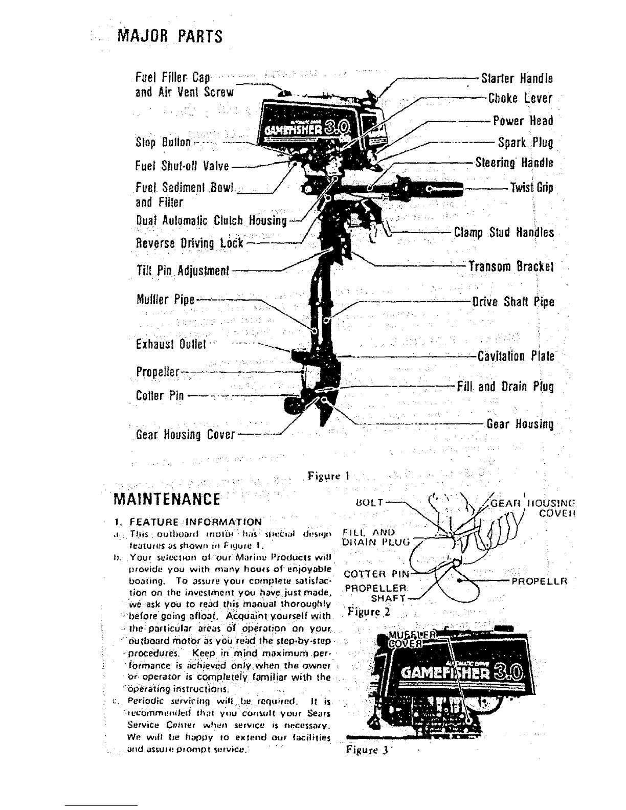
(2) Remove drain plug and washer, then
insert nozzle of gear lubricant tube
into hole.
(3) Squeeze tube until lubricant is forced
out around tube.
(4} Replace p!ug and Washer. Be_ure plug
is tightehed _curely.
(5)
(6)
{3} The outboard motor should be
mounted on astand vertically with
power head up for storage.
(4] Pull starter handle slowly until resist.
ance is felt due to compression pres.
sure. then stoP. Reteas;e starter tension
SlOWly tO prevent engine from revers.
ing rotation due to compression
pressure. This positlon'will close both
the intake and exhaust ports for
storage.
(5) Drain and fill gear'housing as oullined
under Lubrication of Gear Housing.
fRet. 21
[6) Wipe exterior completely with fresh
water Cloth and then apply light coat-
ing of oil,
b. When slatting a new season, always use fresh
gasoline. Last year's gasoline may have
varnish deposits that will plug the carbu-
retor lels. thus recluiring a complete over.
haul.
C. TO plan for the coming season, we recom-
mend you contact your Sears Service
To achieve complete drainage of fubd. : Center before the new season for any semice
cant. remove cotter pin0Propelier andi:: ' _-_.repair work required.
sheep pin from proPeller:shafto, ai=6. :. :; _
gear housing covet b'f unscrewing 2
bolts.
When ub.canthascompletetyarain .OPERATION
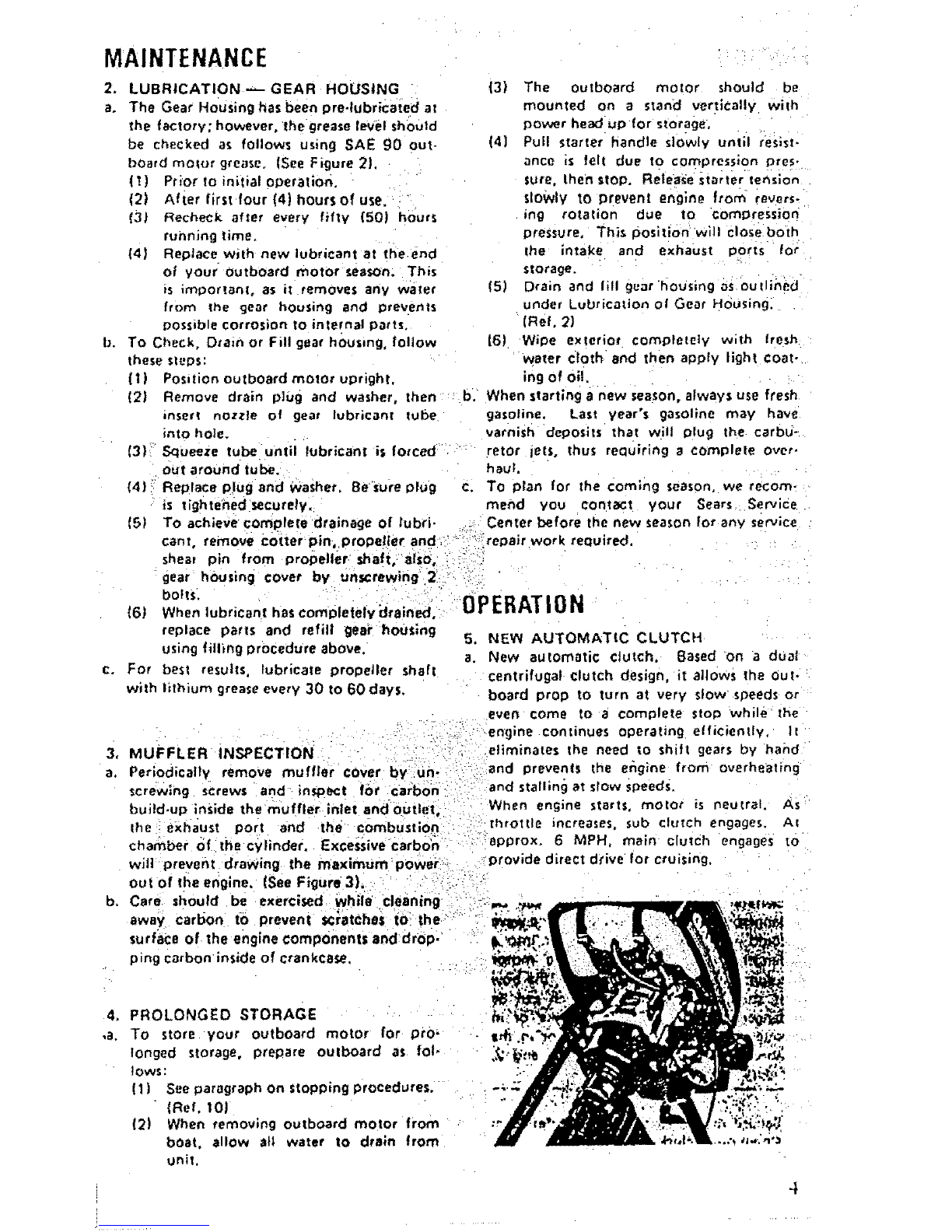
replace parts and refill geai" housing 5. NEW AUTOMATIC CLUTCH
using filling procedure above. a. New automatic clutch. Based on a dual
c. For best results, lubricate propeller shaft centrifugal clutch design, it allows the out.
with lithium grease every 30 to 60days. board prop to turn at very slow speeds or
even come to acomplete stop while the
.engine continues operating efficiently. 1t
3. MUFFLER INSPECTION i:i?': eliminates the need to shift gears by hand
a. Periodically remove muffler cover 13y:.un. ':and prevents the engine from overheating
screwing screws and in._koect f0r Ca_:bo:n and stalling at slow speed._.
build.up inside the muffler inlet andoutlet. When aniline starts, motor ts neutral. As
the ; exhaust port and the combustion throttle increases, sub clutch engages. AI
chamber of the cylinder. Excessive carb0_- ::'. approx. 6 MPH. main clutch engages to
will prevei_t `drawing the maximum powei: provide direct drive for cruising.
out Of the engine. (See Figure 3}, r__%1: "''
b. Care should be exercised While €leaning, _
away carbon to prevent _t-atcbe$ t0:the" ......
sudace of the engine components and drop.
ping carbon inside of crankcase.
4. PROLONGED STORAGE
.a. To store your outboard motor for pro.
longed storage, prepare outboard as fol-
Iows:
(1] See paragraph on stopping procedures.
{Ref. lOJ
(2) When removing outboard motet from
boat. allow all water to drain from
unit.

OPERATION
6. BOAT MOUNTING
,J= Mount the motor on the center at the bool
transom (sternl. {See Figure4).
CAUTION
Hand tighten transom bracket and clamp
stud handles simultaneously. 0o not use a-
wrench Or any other device that would
cause damage to brackets. Occasionally
check to be sure lamp stud handles on
lransom mounting bracket are tight.
|See Figure 5),
l). TO obtain the best performance IIom ybur
uutboard, the |oItowing boat ttaf_som s_)ect-
lications are recommended: (See Figure 4). Figure 4
Transom Angle (See View 3):
........... 12 to 15 degrees
Transom Heigh t(See View 4): L'J_x-._:- €,_ _
.............. 20.7 itii:hes ,."-.L...
_:. The angle o! the motor column is easily :_l_l_i__,_: _
_diusted by removing the Hitch Pin and "
changing the TiIt Lock Bracket Pin in the ,I
llve (5) diHerent angle position holes
rotated o_ either side of the right or lelt
Transom Mounting Brackets. Each angle
position elevates five (5) degrees. Try
center hole position first. (,See Figute 6). =-"
d. To find the correct angle position, make a
test run at full throttle with y0ur usual
iOo'_ng in the boat, Always stop motor to _'
change the Tilt Lock Bracket Pin, The car." Figure 5....
rect angle posit_on will have your boat:.'_
traveling with the bow slighdy higher than.
{he stern, but should not porpolse (bow: !i
rises and falls rapidly and continuously). Be-"
sure Tilt Lock Bracket Pin is always Pushed
completely through both Transom Mount- '.,
ing Brackets and H_tch Pin is secured. _-
V=ew 4
TRANSOM
BRACKET
CLAMP STUD HANDLES
WARNING
If the motor column is tilted too far out,
ward, the boat is likely to porpoise or
cavitate at full throttle, which can be
dangerous because a cross wind or a wave
could suddenly deflect the boat into' a
dangerous' tUrn_ Also, if the motor
column iS_tilted t0o far inward, the bow
of the boat will dig in, which.can be
dangerous when: Crossing a wake or in
cough Water. DO': not run :motor it1' the
storage position. (See VIEW' .1 and 2,
Figure 4),. !
|
i
,'_ Secure motor to boat with Safety Chain. There is a posslbil_ty of losing
backed out too-fat,
Chain not inclu'ded with motor.
..,.r:-u'e6 ......
j T'g ten steering tension bolt us ng a spanner :
I _ for desiied steering effort,(see Figure6), :
CAUTION
'1
bolt if

OPERATIOX
8. 2-CYCLE ENGINE FUEL MIXTURE
Use agood grade of regular gasoline. (See mix- _
in9 table below,)
CAUTION
Always use BIA certified TC-W oil in the
50:1 ratio. Failure to d0to may result ih
excessive spark plug fouling, piston
scoring, or bearing failure. Do not under
any circumstances, use muttigr_Kle , such 8s
IOW.30, or other automobile oils.
If BIA certified Oil is not evaifebie, use
an $AE 30or 40 2-cycle or oiJtboard oil.
We reserve the right to refute warren Won
)arts which are damaged when using
improper fuels or lubricants;
:WARNING
Gasoline is highly flammable. Always mix
in wail ventilated area, Do not fil! tank
with motor running, nor near any flame
or while smoking. Be surevent screws _
and filler caps on tanks are finger t_ght e-
ned when transporting gasoline _ini_the
trunk of your automobile to prevent
explosion,
U.S. Measure
"Regular Amount of oil
Gasoline to be added
In Gallons In Pints In Oz
1 0.16 2.6
3 0.48 _7;7
FUEL , 5 0.80 12.8
!_iMIXING : :6 ':': 0.96:/_15.4 .......
TABLE MattlciMeaSura !:
MIXTURE Reg61ar, ;;i Am0untof0il
Gasoline to bi_ added:
,;, tn Liters ! InLlterlt i
_....H,...,H , , J
•1 • 0.02
_' 5 • 0.10
!_/ _ 10 _0,20
:i 20 0.40
_9_ STARTING PROCEDURE (See Fig.7 & 7A)
a, Open air vent screw located on fuel filler
cap by turning counterclockwlte,
b, Open fuel shut-off valve,
C, Open throttle grip tO half throttle.
d. Move, choke lever to "On'* positiOn.
"WARNING
When starting outboard, the boat will
move with a sudden burst o! speed, Make
sure you ere well sealed so as not to lose
your balance with alast start,
Figure 7
Figure 7A
iFibre S
e. Pull starter handle slowly until you feel
starter engage, Then pull with rapid
motion and allow the starter cord tO
retract slowly. (See Figure 8),
f, After engine has started, gradualiYm0ve
choke lever to "Off" position while
warming up the engine.
g. Let engine idle for approximately 3
minutes before moving throttle grip to
"Fast" position.
10. STOPPING PROCEDURE
To stop engine, move throttle grip to "Stow"
position and press stop button.|See Figure_TA)
6

OPERATION
LWARN|NG _
• In case of an Emergency, the engine can
be stopped by moving the Choke Lever to
FUll Choke Position.
If the motor will not be opelatedif0r_-_
period of time; if it is to be removed from
the boat, or if it is to be tilted:up, we
recommend the following praCiice :to
prevent spi!lage from the carburetor
throat and bowl .and to prevent gum
formations in the carburetor during
storage;
t. Close luel shut-off valve end air
vent screw at fuel fi!ler cap.
2. Allow motor to run at idling speed
until it stops of it= own accord,
indicating the carburetor I_as run
dry.
Figure 9
PROPELLER
Screw
11. FLOODING
To c!ear engine of excess fuel, move choke lever COTTER PIN
to "Off" position and throttle grip _to hal!
throttle position, Pull_ recoil starter handle
until enginestarts and continues to run. Figure !0
12. CARBURETOR ADJUSTMENTS
._ Your me=or has a_dle adiust,ng screw and
b,
the idle spet:d has t)_rt _)rese! _t Ih_ #Qctory.
However, you may need to adjust tt?e idle
speed using idle Adjusting Screw. Turn that
Screw clockwise to increase motor speed-
and counter clockwise to decrease it. The-
idle speed adjustment must be'done with _.
zhrottie grip at lull closed position and the
idle speed should be as low as possible whil_
the engine runs steady. (See Figure 9)
Periodically check filter fordirt by, unscrew-, .:
ing Sediment Bowl (See Figure 12}
13. PROPELLER SHEAR PIN & COTTER
PIN HOLDER
• °
Figure 1I
o. The Shear Pin is used !or the purpose of
protecting the Drive Train and Gears. The
Shear Pin will not prevent the propeller
from becoming damaged when striking an
under water object. When shear pin is
broken, the engine will continue to run, , _. ,,
however, the propeller will not be rotating, !'jgure 1z
CAUTION }
Stop engine immediately after shearing
pin to avoid possiblerdama9 eto the engine.
b. To replace she_r pin, shut otf motor,
_emove collar pin with pliers and slip off
propeller, (SeeF=gures 10& 11].
c. Replace with new shear pin located in shear :.
pin and cotter pin holder, (See Figure 12),
SHE_ i
i
T

OPERATION
14. FLYWHEEL MAGNETO IGNITION
SYSTEM WITH TRANSISTERIZED
ELECTRONIC IGNITOR
a. The magneto ignition system consists of the
following component parts! Flywheel, Tran-
sisterized Electronic Ignitor and ignition Coil.
b. Inmect the following if engine fails or is
herd to start:
_-{1) Spark plug as often as necef4ary. Be
sure t_oark plug gap setting is .025 "°
(O,6mm).
(2) Gasoline fuel supply and fuel-shut.
off valve should be open.
(3) Carburetor being starved of fuel.
c. The correct =park plug for this motor is
NGK 8MR-6A or Campion RCJ-8.
d. To test ignition system, remove mark
plug and place against bare mot on metal
part of motor away from cylinder ==park
plug hose and then pull starter cord several-
times. If asPark bridges the plug gao. the
magneto is in good ooereting condition,
The high tension lead wire must be con.
nected to the plug for this check. If there
is no sPark, have the ignition checked it
your Sears Service Center.
Figure 13
15. REMOVING MOTOR FROM BOAT
a. Always tilt motor by lifting On rear of
shroud, DO NOT PUSH DOWN ON THE
STEERING HANDLE, When removing the
motor from the boat, raise the outboard in
upward direction until the propeller clears
the transom. ::Hold the motor upright long
Figure 14' WARNING
If the motor wil.I not be operated for a
period of time, if it is tO be removed
from the boat. or if it i€ to be tilted up.
we recommend the following practice to
prevent millage from the carburetor
throat and bowl and to prevent g_Jm
formations in the carburetor during
Storage:
f. Close fuel shut-off valve and air vent
screw at fuel filler cap,
2. Allow motor to ru nat idling mead
until ff stops Of its own accord, indl.
caring the carburetor has run dry;
enough tO allow ell water to drain from the 16. SALT WATER OPERATION
exhaust pipe. When you find it difficult to To materia!ly'increase =the life of all exposed
hold the motor uptight, tighten the Center parts and decorative finishes, follow the steps
Bolt increasingly for desired effort. (See indicated below.
Figurel3). ' Always tilt ybur motor out Of thewater
WARNING - when not in use. :
Although the engine is: air ¢oolecl, it iLs I _ b. Never leave the lower un!t in salt' water
posslble to burn your hands on the engine J rovernight. •
€._ Wipe e'xteri0r comp|etely with fresh water
blOCkDonotandtouch.UpPerportion of the column. J cloth and then apply light c0ating Of gill
Id. Lubricate prope_ler shaft occasionally with
a_waterproof_Wpe of lubr cant {Lithium
b. It may be necessary to rotate the motor to : Grease) , thu senabling the propeller to be
one side before tilting the motor on the removed easily.
transom to remove leg from the water when e_ It is good practice when operating insalt
installed on boats with thick transoms. : _'water. to inspect your motor daily and to
C,-Always carry outboard with the engine': .... apply a light coating-of grease to any
.above the lower unit to prevent moisture part or area that shows evidence of cot-
from entering the engine through the .... rosion or rust. '
exhaust ports, f. Always remOve motor from boat yar-
d. Steering handle serves as carrying handle as tically, allOwing water to drain from column
shown in Figure I4, before tilting the motor. ......

TFIOUBLESHOOTING CHECK LIST -.
*Take you_ outboard motor into =_nyone of over
2000 Sears Sq=viee Units.
XX
x X
Ix x
X X
"l'a=t kEmpty
Fuel t ....... :-
Shut,OH Valve Closed -:
X X Fuel Line Kinked o( Pinched . .... :uu,,_ i............ '
X Fuel Filler Dirty or Clogged "
X Vent Screw on Fuel Tank Fihe_ Cap Closed
Carbufet0= Pass_get Clogged 0_ Di;.'ty
Incorrecl Fuel-Oil Mixlure
Carbu_'elor Out o( /_liu_tmenl - .
Engine Flooded
Wrong Type Spark Plug
X × X .
_'i-T- x × x .....
F-_.... Z'" x--'_---_'--
× X r
XXX X X
X X XX X Defective or Fouled Spark Plug
L--__ × I .... I DeI..,.e.o.°e,O,.... __. "...... "
XSPa_k Deal Not Jump Spark Pug Gap ,,""
X Engine'Ou! of Timel, . :
XXX Transi_;terlzed Electronic Ignitor oU! of order -= •
I X : X " X X X Weak Ignition Coil' : "
XISpark Plug Lead Wire Not Seeuzed
_X J " "•X Frayed or Cracked Lead Wire Insulation "
. . l s
X ' X " " Disconnected.... Grounded at Loose Wiring in Electrical System. "
I x, .ero_.e,gound.by_o,e!.g%pbi_c,=CF=_h__!,0Line[ Weeds,ElcJ ......
XI.High Tenllon Lead-Sail Waler Build Up
IMPORTANT INFORMATION
MODEL NUMBER: 298.586191
SERIAL NUMBER
DATE OF PURCHASE
INSURE YOUR ENGINE
Many insurance companies including Allitale
Insurance offer protection contracts for your
boat and outboard engine. Insurance covering
yOUr Own equlpmenl against damage, Iheh,
etc._ as well as liability insurance for property
damag e and personal injury to others is availa-
ble, I! would be wise to €ontact your insurance
agent for further intorn_alion abOut adequate
protection.
IDENTIFICATION PLATE
." OPERATING LOG
NO. HRS, USED G_LS, FUEL USED
......i............ :
DATE NO. HRS. USEO: GAtS FUEL USED
9

REPLACEMENT,PARTS
FOR
MODEL No.298.586191
I0

FIG'1 ENGINE
32
75
74
31
B5
86

FIGol ENGINE
REF.No. P.P,No.
o_e+_o2ol.zou
;sT.o4ooo+goo
018-00540-200
002-10200-803
017-10200-202
040-10100+ZOO
041-10|00-201
03_-02000-20!
031-10100-210
Q_t-_OIQO-200
048-I0242-800
088-02000-E00
ggg-O1820.300
999-6_|73.000
ggg_82101"004
1Sg-21401"871
07|'02007_210
QT}-O200T*220,
07t-i02007+230
071_02007_2(0
gg9+01620*200
ggg+_'iS3-000
090+:10200,20Z
072-10242-t10
161-20751-801
lg4*OSOtS*800
IS$+21717"801
112.:10242-200
085_02501-200
ggl-OOlO0-O01
198+11100-200
250-01048+200
ggO-ll050-10l
ggZ-01050-041
g00-11000*302
902-10O80-042
990-15040.10Z
ggo*l1040-182
992"!0040"042
OgO+11000"Z52
992+100G0_042
Qg2"10080-042
990-_10a0-|82
g92-010S0-0_1
990"11050"102
gQ2-t0040-042
PARTS NAME
:YLIHD[I SHIOHD
;PALE PLUG CAP ASS'Y
SPAI[ PLU_-BHESA
_YLIEOEE COEP, •
:+[IMDEI Gks£ET '
p:ISTON ||KG++ ......
PI$TOH+:_II_G
_ISTOXPIX CI|CLIP
PISTOH_+ ,'
PISTON tll 1¢I35"
C[ANI+$HAFrT_OMP.
HOOD+IUPF £EY 3Xi+X$.
ALL BEAEIgG 10203 :
IL SEAL 17301 ._
IGMITOI COMP. TT|+IE !
_IAMK SHAPT SHIH O.lO
_|&_ SHA_] SHIM O+Z5
Ct-A_I SHAFT SHI_ 0,20 +
CIA,I"$HAFT SBIH 0.30
BALL HEALING 18202
I_ SEAL |$30,7
:iA_I CASE GA$1ET
_gANE CASE ASS'Y
IOHITIOH COlLCONP.
+OIO+_LAmP CO_P.
XAGMETO+_6TO_ COXP+
FAH CASE
FLYVH£EL HASIJEI
KUT I0 {L+H. TtIEEAO)
_OIO'CLAMP L +
SPAI£ PLUG _UBBEB COVER B
$C_EV 5110
VASXEt 5
S_XEV 8X30
S.tASIIEI 8
$+IEH 4XIO
SCX[V4XI+
S.VASHE_ 4
$CREV _X25
S.¥ASEEI
S.:VASEEE
$CXEV 5X|&
HASHER S
S_IEV 5XI0
_.VASKE! 4
O'ly
I
2
I
I
I
I
I
V
l
l
t

IG.2 TANK, CLUTCH & MUFFLER
fIG,3
102
1oo
43
_5
56
55
3O 34 P_._._-41
5o

: i /:// ¸¸7¸::¸: •
FIG.2 TANK, CLUTCH & MUFFLER
PARTS NAME
TANK CAP ASS+Y
TAXi CAP GASIET.
ENGINE COVER (SEALS)
CUSHION HUiBEI
COLLAI
STANTEI PAUL EASE
STAZTEI PAVL SPNIHG
STAITEl PAUL
STEPBOLT
FUEL TAXI
FUEL TAME BAND COMP.
FUEL TAN[ DBACXET CONP+
FUEL TAXI BEACKET 9
TA#I SHPPOIT IUOBE!
FUEL TAXI CUSHION _UBBE_
PUlL TAXI CUSHION lUeBEX
PET+COCK AS$*Y
PET-COCI FIXING NUT
FUEL PIPE SXBXIID
FUEL PiPE 4,SXBXi40
CLIP D
rIM HOLDEI
STOP BUTTON COVEI
STOP BUTTO_ COHP.
STOP lgtTOX FIXIXO NOt
SPECIAL S,MASHEI
IHLET MAAIFOLD GASIET
INLET MANIFOLD
CLIP 7,5
All CLEA#EI ASS'¥
CLUTCH FLANGE
CLUTCS SPIING COMP,
CLUTCH VASItEB A
CLUTC_ AIM COHP,
CLUTCff UASHEK I
CLUTCX STEP BOLT
CLUTCB SPIING
FLYV_EEL VASHEE
XUT IO (L.U. TIINEAD)
HHFFLEB GASKET
MUFFLEI BOOT A
HUFFLEN GAS[ET
XUVFbEI BoDY i
MUFPLEI PIPE GASEET
MUFPLEI PIPE STAY A
MUFFLE! PIPE
KUFFLEI PIPE BIACIET k
MUFFLER +PIPE BIACtET 8
SCIEV 5X45
S.VASXEI S
VASHE| 5
$CIEV 6X12
$.VASHE! 6 +
lot 6
S.UASREE 6
$ClgH 4X30
$,VASHEE 4
$CEEV OX20
$.VA_KEI B
SCUEV 4X12
S.VASHEI 4
_CEEV 5EI2
$.VASHEES
$CEEV 6E25
S.VASHE| O
SCI_V 5X12
S.VASHEI &
VASHEI 5
SCIE_ BXI2
SMALL VASHEI S
SiSAl PIN
COTTE| PIN
FUEL PIPE COl_
HOSE CLAMP AS$'Y
lIGht SlOE HAll (SEALS)
LEFT SIDE MAll (SEALS)
NAME PLATE (SEALS}
SVAIT£1 HAlE (SEALS)
[$+VASflEI O
)'ly

JG,3 RECOILSTARTER
13
. - .... 26
REF.No. P.P.No, PARTS NAME Q'ty
13-000 7S_-I0207-g00 EECOIL STARTEI ASS'Y 1
_00| 772-10207-200 RECOIL STAR?El BOOY 1
-002 774-10200-200 STARTER ROPE REEL .... ,_ |:
-003 770-10200-203 EECOIL SP|IflG . . i: t
:OOg T83-01006-20| sTAITI! tOPE '. !
-011 780-10201-200 LOPE GOIDE |
-012 785-10207-20! STAETER HAROLE :! :I:
:013 833-10207-200 STAITER RANDLE CAP' l
:0)4 092-0|040-011VASRE| 4 ' .... | ,
-015 773-10200-200 PgLLEY SgAFT/ouTER .... i 1 "
-Ol? 000-110S0-25| $CR[V 5R25 - :" • i
:010 ?70-10200-200 RECOIL SfllNG C_SE :: I
_019 827-10200-201 _COIL SPRING ffOLDEI iili I
_020 990-1|050-122 SC|[V 5XI2 ,2
-021 gg2-|OOSO-042 S,VASBE| _ 2
-022 992-01050-041VASI[R5 ,1
-023 902-10050°042 $_VASHER SI
-_024 991-41050-022 CAP gUT S !
-020 780-I0200-200iSTART_R VASWE| :: l'
t:
-03o 791-1o2oo-2oo. STARTER DISHING _::

FIG.4 CARBURETOR
39 ©
{_ .......... 40
..... 29
-21
30 -"
31 -- _'_
REF.No. P.P;No.
-o02 597-zolzo-2oo
4-003 595-20200-200
4-004 594-20202"200
1-005 _19-20Z02-200
4-000 593-20202_200
1-007 592-2002T'920
t-008 591-2005?-200
_-OIO 023;_1700-200
4-011 022-202|7-200
4"012 fiSI-20202-gO0
4-016 _07-20Z|0"200
1-017 599-2001T-740
4"021 800"20202-200
4"024 gg4;34010"lOb
4-026 -]805-202o2-20o
t-027 003"20100-200
4-021 ]026-20202-200
4-029 601-20110"200
4-030 829°20202-200
1-031 627-20400-200
4°03? 57_-20200-200
4-038 602-20420-200
1-039 $96-20202-200
4-040 Sge-2OOST'9SO
CAteU_TO_IXSS'Y .....
CABLE ADJUSTER
EODY CAP
TltEOTTLE VALVE SP_iMG
THEOTTLE SPE|EG SEAT "
!JET WEEOLE CLIP
JET WEEgLE ASS'Y 004
THEOTTLE VALVE O.5Xt.5
_ADJUST SPRING
ADJUST SCRE¥
!OUTLET CLIP ASS'Y
FLOAT CKAWBEE GAS[ET
EAIN JET m?4
;FLOAT CHAWBER ViT_EAD
5CEEV 4XI0t$
CHOXE PIE
N_EDLE VALVE
FLOAT AEN
FLOAT
!DtAIX SCREV GASKET
BRAIN pLUG
NANIFOLD SEAL
XEEDLE SEAT
CABLE AOJUSTEE LOC[ NUT
WEEOLE JET .Zoos
PARTS NAME_ :i'O'ly
!
I!
I!
:II
" l
I
I
!
I
}
2
]"
i
!
!
!
I
l
!
1
1;

FIG:5 HANDLE & BRACKET
8
9
13
12
II
10
72
P3
24
28
25
26
,41 20
IF 40

FIG.5 HANDLE &BR'ACKET
REF.No. P.P, No.
5.000 a70-35552-000
5-001 aSS-O;OSS-ao0
S'00S 200"35300-100
5"OOa 003-51042-00Z
5-007 000-8|800-404
5-OOa 003-50020-002
5-000 185"35300-203
S'O|O 090"21060-252
5-01| gOZ-lO060-O42
5-012 000-11050-202
5-013 002-10050-042
5-014 1_|-35500"202
5-OIS 703-10Z00-20|
5-0|6 992-04080-031
5-017 L6Q'35552"800
S_O|O 182_35500-200
5*020 900-2|080-_0Z
5-02| ]92_01060-04
5-022: 09|-010_0-021
5-023_ _092-|0080-042
5-0241 134-35500-201
5-025! IL15,35300-2t0
S-02B |3|-35308-200
5"027 :13e-35500-20
5"026 900,21000-|0Z
5-020 ggO*It050-1"_2
5-030 _ 002-|0050-042
5-031 |37-35500-20|
5-o3z tsa-3ssoo-2o|
5-033 012*|0050-042
5"03! r 900-11050:|2;
5-035 139-35S00_200
5-036, 129:3S100-20o
5-037 123;35500-20|
5"03_ 1107-35|18-801
$-030 |08-35||0_'80!
5-040 000;210_0-752
5-04; 108-35505-2o0
5_042 QO[-4|OeO-022
S'04]- 002-'|_00_0-042
5-044 902-0t060-04!
5"045 8TI-35552_:200
5"048 8?2-35552_200
5-047 873-35552-200
5-048 874,-355_2;200
5-040 _75",35552:-200
S-050 878"35552*200
5"05| 879"35552;Z00
5-052 090-11050"202
5-053 091-0|050-021,
5-054 877-35552-200:
5"055 8T8"35552-200
5-056 003-3220)-200
PARTS NAME
TVIS] GK|P kSS'Y
t|II0TTLE VI_E COHP,
CLUTC8 OlUN C0HP.
_TOP IIRG C42
EALL BEAE]EG sO004DD
STOP IIHG C20
CLUTCH CASE
REX. _OLT 6X25
S,VASllE! 8
SCIEV 5120
S.VASXEE 5
HAEDI, E STOPP_E
STEP 80LT
VAVE VASHE_ E
STEEEIRG RARDLE CORP,
HANDLE VASEEI
BOLT EX30
VA_IIEI 8
_UT_
S._ASHEI 8
TXEUST VASHEE
EEACEET
TX_UST 8IACEET
EETUE_ tAX
80LT _lO
5CIEV 5XI8
5.VkS_EI 5
|ETUDE CkX GUIDE
_ET_E_ _UiGE PLATE
S.VASHEI 5
SCIE¥ 5X12
IETOIK $_IIRG
BtkCiET PiN STOPPE_ A
8_AC_ET P;IN 5
CLAHP BIACEET B CO_P.
CLAHP-BEAC[ET ^CORP.
_OLTSX75
_Lk_P 8_Ct_T BUSIilNG
CAP N_T
S.VAS_EX e,i:
VASXE| 6
TXIOTTLE G|IP
THSOTTLE INRE! PIPE
fflZOTILE _OLOE_ A ,_
TR_OTTLE CO'DEe S
TH_OTTLE,:XOLOEE'COVEe
VIEE GUIOE; ,.
TAPPIKG SCEEV" ". _
SClEViSX20 :
ROT 5
_let_LZ STOPPE_
TX_OTTLE STOPPEE SPZI_G
Vile CLAHp 8A_0 ....
O'ty
t
i
|
I
I
!
I
2
2
,4
1
!
I
I
2
!
!
I
!
I
I
4
!
!
1
1
1
I
|
I
l
I
!
2
t"
!
|1
!
I
I
I
I
I
Z:
2
1
1

FIG'6 DRIVE SHAFT PIPE,& GEAR ICASE
38
39
! 30
29
21
23
--13
Table of contents
Other Gamefisher Outboard Motor manuals
Popular Outboard Motor manuals by other brands

MotorGuide
MotorGuide X3-40 Operation and maintenance manual

Mercury
Mercury XR2 user guide

Mercury
Mercury 300XS OptiMax user manual

MINN KOTA
MINN KOTA RIPTIDE INSTINCT QUEST owner's manual

Side-Power
Side-Power SE 130 IP Installation and user manual

Mercury
Mercury 75 Operation maintenance warranty installation manual