Gamma Dental Reference SL User manual

Instruction Manual
Reference SL Articulator and Face Bow Systems
Reference AB, Reference AB junior, Condylograph Set,
Condylograph comfort Set, and Condylograph comfort Set I

Instruction Manual
- 2 -
Important notice:
For your own safety, as well as for operational safety, please read these instructions
thoroughly before beginning to operate the device. Always comply with any and all
warnings included in these instructions, and/or on the device itself.
Manufacturer:
GAMMA Medizinisch-wissenschaftliche Fortbildungs-GmbH
A-3400 Klosterneuburg, Josef Brenner-Straße 10

Reference SL Articulator and Face Bow Systems
- 3 -
Instruction Manual
Reference SL Articulator and Face Bow Systems
Reference AB, Reference AB junior, Condylograph Set,
Condylograph comfort Set, and Condylograph comfort Set I
Curve of Spee Analyzer
CPV (Condylar Position Variator)
Revision
2019-07-22
© Copyright 2019
GAMMA Medizinisch-wissenschaftliche Fortbildungs-GmbH
Josef Brenner Straße 10
3400 Klosterneuburg
Austria
Phone: +43 2243 34140
Fax: +43 2243 34140 90
E-Mail: office@gammadental.com
Internet: www.gammadental.com

Instruction Manual
- 4 -
Contents
1Warnings and safety information ................................................................ 5
2Intended purpose and mode of application................................................. 6
3Reference AB face bow.............................................................................. 7
4Reference AB junior face bow.................................................................. 11
5Reference SL articulator........................................................................... 15
5.1 Introduction .............................................................................................. 15
5.2 Mounting system...................................................................................... 15
5.3 Transferring the upper jaw model according to the anatomic axis ............ 17
5.3.1 Using the Reference AB face bow............................................................ 17
5.3.2 Using the Reference AB junior face bow .................................................. 20
5.4 Transferring the upper jaw model according to the kinematic axis............ 20
5.4.1 Using Condylograph comfort Set or Condylograph comfort Set I.............. 20
5.4.2 Using Condylograph Set........................................................................... 27
5.5 Mounting the lower jaw models in the articulator ...................................... 35
5.6 Eccentric articulator programming............................................................ 37
6Adjusting the Reference SL articulator ..................................................... 41
7Curve of Spee Analyzer Set ..................................................................... 49
8CPV (Condylar Position Variator) ............................................................. 55
9Maintenance and cleaning........................................................................ 59

Reference SL Articulator and Face Bow Systems
- 5 -
1 Warnings and safety information
The instruments are designed for use in the dental practice and lab. Initial start-up
and operation must be according to the instruction manual.
Furthermore, it is the owner's responsibility to check up on the adequacy and ap-
plicability of the devices for the intended purpose before initial start-up, unless it is
listed in the instruction manual.
The manufacturer does not assume liability for damages caused by improper usage,
incorrect handling or improper repair.
All maintenance and servicing tasks, other than operations mentioned in the instruc-
tion manual, should only be done by authorized specialists.
Use original GAMMA spare parts only!

Instruction Manual
- 6 -
2 Intended purpose and mode of application
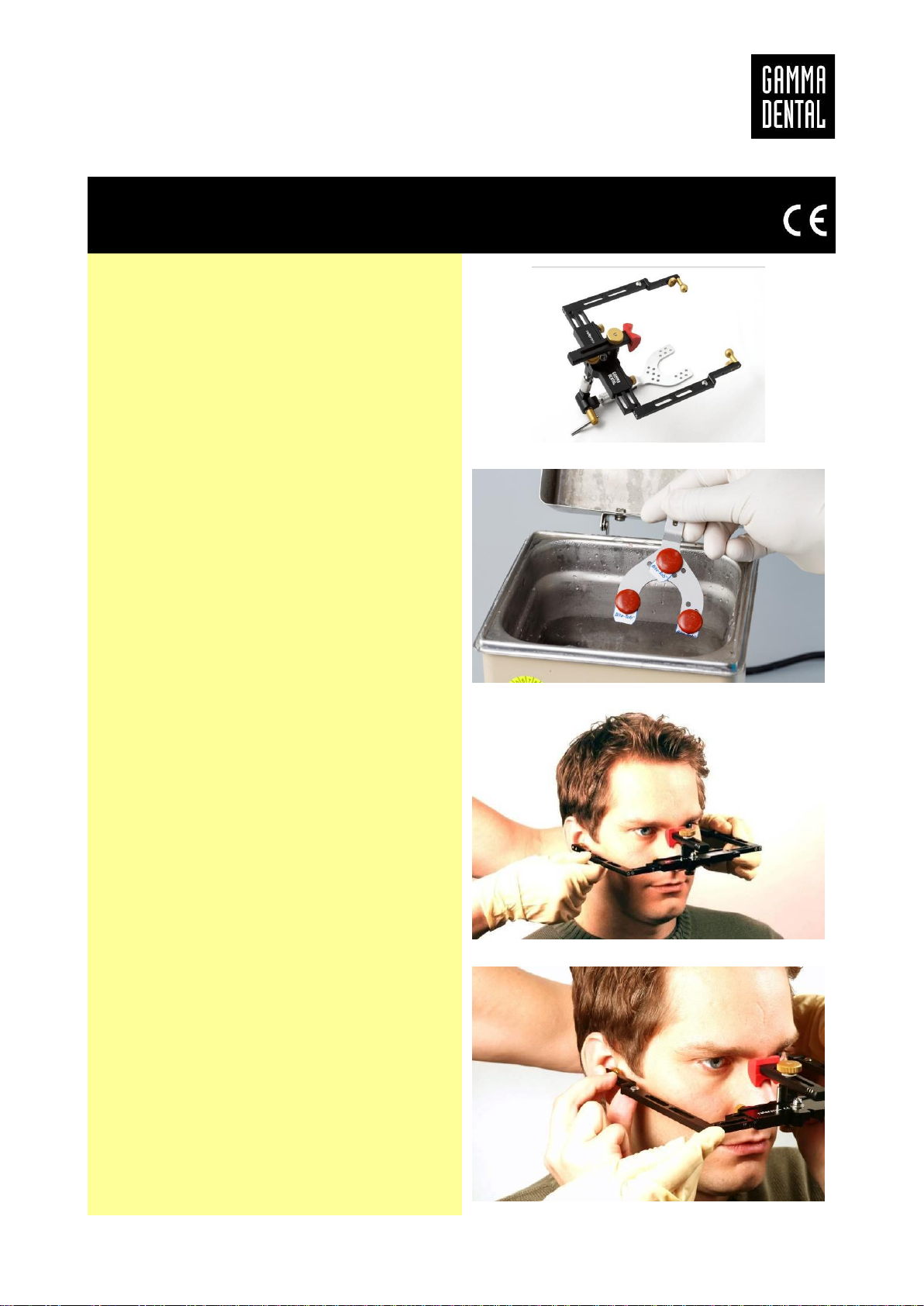
The face bows of the Reference system serve two purposes. Firstly, they are required accessories
to the CADIAX system, because the flags and styli of the CADIAX are mounted onto the face
bows. Secondly, theface bows are usedfor determining the relation of the patient’s jaw to a cranial
reference plane. This assessment of jaw relation is necessary for mounting the jaw models in the
correct position within the articulator.
During the application of the face bow, the following circumstances can prevent or limit the usage
of the face bow:
•General diseases:
Patients with diseases that prevent the mounting of a face bow. The diseases can be phys-
ical or psychological in nature. (e.g. spasticity, epilepsy, claustrophobia, injuries or dis-
eases regarding the bony skull or soft tissue structures of the skull, such as the ear, etc.)
•Special diseases in the aural area:
Patients with diseases in the area of the ear. (e.g. painful inflammations, tinnitus, pain in
the ear, etc.)
This instruction manual describes the application of the devices. The usage of articulators and
face bows is part of the dental medical education. A briefing regarding the handling of the products
by our own personnel or by personnel of our retailers is not required.
Interference and/or operation of the devices by the patient is not intended. However, active coop-
eration of the patient is necessary for obtaining the desired examination results. For this reason,
special attention has to be given to the patient’s cognitive abilities during the examination of chil-
dren, elders or handicapped people. This group of patients has to be carefully prepared for the
examination in particular.
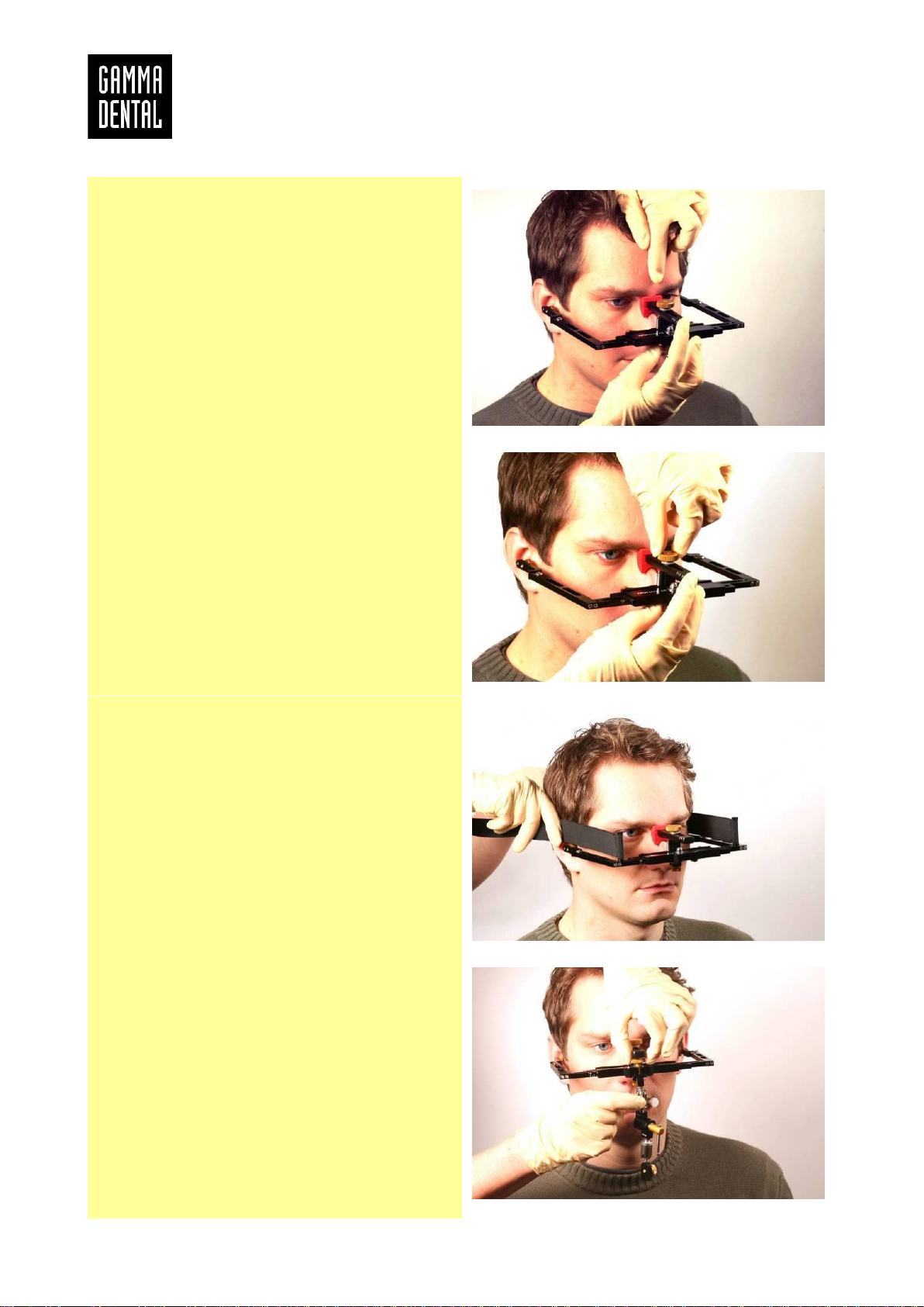
The application of the face bows on the patient during the assessment of jaw relation is completed
in a few minutes. Articulators are not used on the patient.

Reference SL Articulator and Face Bow Systems
- 7 -
3 Reference AB face bow
The Reference AB face bow (06-230430) is
used for mounting the upper jaw model into the
Reference SL articulator, according to the ana-
tomic hinge axis.
Soften the Bite Tabs (06-642150) in warm water
at approximately 45C and place three of them
on the bite fork. Apply wax to the bite fork.
Place the prepared bite fork onto the upper
teeth of the patient in median-sagittal direction
with slight pressure on all waxed points. Try to
get equally shallow impressions. The teeth
should not touch the metal fork.
Loosen the glabella support. The 3D joint sup-
port is not yet attached to the face bow. Insert
the porus supports into the patient's ear canals.
Tighten the screw to fix the position.
Gently push the porus supports into the ear ca-
nals.

Instruction Manual
- 8 -
Stretch the forehead skin.
Push the glabella support carefully and without
pressure onto the nasion and tighten the Gla-
bella support screw.
Optionally, to improve the stability of the face
bow further, you can attach the retention straps
(01-SP0040). Stretch them equally on both
sides and close them at the back of the head
with the hook-and-loop fastener. Control that
the face bow fits properly.
Attach the bite fork to the face bow with the joint
support.

Reference SL Articulator and Face Bow Systems
- 9 -
Press the bite fork gently onto the upper teeth.
Tighten the toggle nut of the joint in two steps:
Step 1: to fix the bite fork in-situ, and
Step 2: for safe transportation.
Centralize the toggle and hold the joint support
with the other hand to counter the torque and to
absorb the pressure on the glabella support.
The face bow is in correct position and the joint
support fixed without tension, when the bite fork
will not drop considerably lower from the upper
teeth.
Open the face bow and pull it carefully away
from the patient, in forward and downward di-
rection. (If retention straps have been used,
open them carefully in advance.)

Instruction Manual
- 10 -
The procedure on the patient is completed.

Reference SL Articulator and Face Bow Systems
- 11 -
4 Reference AB junior face bow
The Reference AB junior face bow (06-230430-
J) is used for mounting the upper jaw model into
the Reference SL articulator, according to the
anatomic hinge axis. This face bow is intended
for children and people with smaller cranial
width.
Soften the Bite Tabs (06-642150) in warm water
at approximately 45C and place three of them
on the bite fork. Apply wax to the bite fork.
Place the prepared bite fork onto the upper
teeth of the patient in median-sagittal direction
with slight pressure on all waxed points. Try to
get equally shallow impressions. The teeth
should not touch the metal fork.
Loosen the glabella support. The 3D joint sup-
port is not yet attached to the face bow. Insert
the porus supports into the patient's ear canals.
Tighten the screw to fix the position.

Instruction Manual
- 12 -
Gently push the porus supports into the ear ca-
nals.
Stretch the forehead skin.
Push the glabella support carefully and without
pressure onto the nasion and tighten the Gla-
bella support screw.
Optionally, to improve the stability of the face
bow further, you can attach the retention straps
junior (01-SP0040-J). Stretch them equally on
both sides and close them at the back of the
head with the hook-and-loop fastener.

Reference SL Articulator and Face Bow Systems
- 13 -
Make sure that the face bow fits properly.
Press the bite fork gently onto the upper teeth.
Attach the bite fork to the face bow with the joint
support.

Instruction Manual
- 14 -
Tighten the toggle nut of the joint in two steps:
Step 1: to fix the bite fork in-situ, and
Step 2: for safe transportation.
Centralize the toggle and hold the joint support
with the other hand to counter the torque and to
absorb the pressure on the glabella support.
The face bow is in correct position and the joint
support fixed without tension, when the bite fork
will not drop considerably lower from the upper
teeth.
Open the face bow and pull it carefully away
from the patient, in forward and downward di-
rection. (If retention straps have been used,
open them carefully in advance.)
The procedure on the patient is completed.

Reference SL Articulator and Face Bow Systems
- 15 -
5 Reference SL articulator
5.1 Introduction
REFERENCE SL ARTICULATOR
06-231380
The Reference SL articulator is an adjustable articulator, designed for use in the dental practice
and lab. The device is used in the spatial mounting and relation of jaw models, in movement
simulation, as well as in additional diagnostics and reconstructive procedures, applicable for den-
tists and dental technicians.
The articulator offers a mounting system with integrated magnetic retention, by which models of
the upper and lower jaw can be fixed in specified spatial relations to a coordinate system (e.g.
Frankfort Horizontal facial plane). The SL articulator is equipped with both right and left condylar
joints, for movement simulation. These elements are individually interchangeable in their charac-
teristics and offer the possibility of defining the inclination angles for both the sagittal as well as
the transversal components of the guidance.
5.2 Mounting system
REFERENCE Distance blocks
06-231510 (pair, horizontal 1, standard)
06-231511 (pair, horizontal 2, + 8 mm)
06-231512 (pair, horizontal 3, + 16 mm)
06-231520 (pair, slanted A, standard)
06-231521 (pair, slanted B, + 8 mm)
06-231522 (pair, slanted C, + 16 mm)
REFERENCE Mounting plates
06-231550 (50 pc.)

Instruction Manual
- 16 -
The distance blocks and the attached mounting
plates are used in fixing the cast models to the
upper and lower articulator units, to establish
the necessary retention for the cast.
The mounting plates must be screwed to the
distance blocks with the 2.5 mm Allen key.
The mounting plates are disposable parts and
should be stored with the models.
The distance blocks are designed for multiple
use and can be screwed into and unscrewed
from the mounting plate.
To enable exact identification of the distance
block, the type of base used and its position are
encoded in the cast. When remounting a block,
the correct type and position can be easily de-
termined.
Nevertheless, for reasons of precision, it is rec-
ommended that the distance blocks and mount-
ing plates are not separated until after comple-
tion of the case. For manufacturing technologi-
cal reasons, the distance blocks and plates may
differ slightly.
To mount the block into the articulator, the block
is placed at the posterior attachment edge and
then lowered and locked onto the guiding pins.
The block is retained by the magnet, located in
a metal case, built into the articulator.

Reference SL Articulator and Face Bow Systems
- 17 -
Removing the blocks must only be done with
the red release buttons. Incorrect ejection of the
blocks (e.g. by tilting or turning) can cause the
block to detach from the mounting plate!
5.3 Transferring the upper jaw model according to the anatomic axis
5.3.1 Using the Reference AB face bow
This chapter describes the direct transfer of the
upper jaw model from the Reference AB face
bow into the articulator. For directly transferring
the model using transfer stand AB2 (06-
231400) or indirectly transferring the position of
the bite fork using transfer stand AB (06-
216280), please refer to the actual version of
the respective manual.
After taking off the face bow from the patient,
remove the porus supports from the side arms,
thus making the mounting registrations (adapter
plates) accessible.

Instruction Manual
- 18 -
Close the centric locks (left and right) of the ar-
ticulator. For more exact results, we recom-
mend that you insert the black SCI inserts into
the condylar housings in advance. The articula-
tor should be adjusted symmetrically (e.g., 40
SCI).
Preparing the articulator for mounting: first, re-
move the incisal table and the incisal pin unit;
then, the face-bow support (06-230480) and the
bite fork support (06-230585) must be attached.
The correct position of the face-bow support is
achieved, when the writing can be read nor-
mally. The supporting beams of the bite fork
support, equipped with a pressure spring, must
be moved downwards and fixed.
The upper part of the articulator remains open,
resting on the upper index pin.
Move apart the side arms of the Reference AB
face-bow leading parallel and remove the na-
sion support from the bow.
The adapter plates can now be tilted and fixed
to the corresponding casings. To do so, the Ref-
erence AB face–bow is pushed together gently
but firmly, until both guides slide firmly in place
on the articulator, without wobbling. After lock-
ing it in place, theface-bowis placed on the bow
support, and the anterior bow fixing screw is
tightened, thus locking the bow.

Reference SL Articulator and Face Bow Systems
- 19 -
Now the bars of the bite fork supports can be
moved upwards, until they touch the bite fork;
then they can be fixed. The position of the bite
fork must not be altered.
The next step is selecting the ideal distance
block. First, the upper jaw model must be set
into the corresponding impressions on the bite
fork; then close the upper section of the articu-
lator that it rests in solid contact on the anterior
face-bow pins. Analyze the distance between
the upper section and the model. The distance
block which best fills the spatial requirements
can now be chosen. Make sure that there is a
thin, but even layer of plaster on the selected
block. This will minimize the distortion effects of
plaster expansion.
The articulator can now be opened and the dis-
tance block, with mounting plate already at-
tached, can be fitted in. Moisten the model, and
make sure to apply sufficient mounting plaster
on both the mounting plate and the model.
Close the articulator and allow the plaster to
harden, following the manufacturer’s instruc-
tions.

Instruction Manual
- 20 -
The Reference AB face-bow can now be re-
moved from the articulator.
5.3.2 Using the Reference AB junior face bow
For directlytransferring the upper jaw model us-
ing transfer stand AB2 junior (06-231400-J) or
for indirectly transferring the position of the bite
fork using transfer stand AB junior (06-216280-
J), please refer to the actual version of the re-
spective manual.
5.4 Transferring the upper jaw model according to the kinematic axis
5.4.1 Using Condylograph comfort Set or Condylograph comfort Set I
Mounting the upper jaw model in the Reference
SL articulator, according to the kinematic (ex-
act) hinge axis and individual reference plane,
is carried out using the Condylograph comfort
Set (04-GCR311) or the Condylograph comfort
Set I (04-GCR311I).
This manual suits for next models
5
Table of contents
Popular Dental Equipment manuals by other brands

Villa Sistemi Medicali
Villa Sistemi Medicali ROTOGRAPH-D Service manual

ARIBEX
ARIBEX Nomad Pro 2 Operator's manual

Belmont
Belmont Voyager III operating instructions

KERR
KERR OptiBond Solo Plus instructions

Durr Dental
Durr Dental VistaScan Mini Easy 2.0 Installation and operating instructions

KERR
KERR Demi L.E.D Curing Light Operator's manual