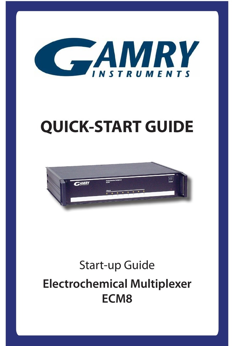
Gamry ECM8 User manual

ECM8
Electrochemical Multiplexer
Operator's Manual
Copyright1991-2005 Gamry Instruments, Inc.
Revision 5.0
September 26, 2005


i
If You have Problems
Contact us at your earliest convenience. We can be contacted via:
Telephone (215) 682-9330 8:00 AM - 6:00 PM US Eastern Standard Time
Fax (215) 682-9331
Mail Gamry Instruments, Inc.
734 Louis Drive
Warminster, PA 18974
USA
If you write or fax us about a problem, provide as much information as possible.
If you have problems in installation or use of the software, it would be helpful if you called from a phone
next to your computer, where you can type and read the screen while talking to us.
We will be happy to provide a reasonable level of free support for registered users of the ECM8
Electrochemical Multiplexer. Reasonable support includes telephone assistance covering the normal
installation, use and simple programming for the ECM8 on standard AT compatible computer hardware.
A service contract that extends both the hardware warranty and software update period is available at an
additional charge. Software updates do not include software enhancements offered to our customers at
additional cost.
Enhancements to the ECM8 and its software library that require significant engineering time on our part can
be performed on a contract basis. Contact us with your requirements.

ii
Limited Warranty
Gamry Instruments, Inc. warrants to the original user of this product that it shall be free of defects resulting
from faulty manufacture of the product or its components for a period of two years from the original
shipment date of your purchase.
Gamry Instruments, Inc. makes no warranties regarding either the satisfactory performance of the ECM8
Electrochemical Multiplexer including the software provided with this product or the fitness of the product
for any particular purpose. The remedy for breach of this Limited Warranty shall be limited solely to repair
or replacement, as determined by Gamry Instruments, Inc., and shall not include other damages.
Gamry Instruments, Inc. reserves the right to make revisions to the system at any time without incurring any
obligation to install same on systems previously purchased. All system specifications are subject to change
without notice.
There are no warranties which extend beyond the description herein. This warranty is in lieu of, and
excludes any and all other warranties or representations, expressed, implied or statutory, including
merchantability and fitness, as well as any and all other obligations or liabilities of Gamry
Instruments, Inc; including but not limited to, special or consequential damages.
This Limited Warranty gives you specific legal rights and you may have others which vary from state to
state. Some states do not allow for the exclusion of incidental or consequential damages.
No person, firm or corporation is authorized to assume for Gamry Instruments, Inc., any additional
obligation or liability not expressly provided herein except in writing duly executed by an officer of Gamry
Instruments, Inc.

iii
Disclaimers
Gamry Instruments, Inc. cannot guarantee that the ECM8 will work with all computer systems, operating
systems, and third party potentiostat hardware.
The information in this manual has been carefully checked and is believed to be accurate as of the time of
printing. However, Gamry Instruments, Inc. assumes no responsibility for errors that might appear.
Copyrights
ECM8 Operator's Manual copyright1991-2005, Gamry Instruments, Inc.
Gamry Framework copyright1989-2005, Gamry Instruments, Inc.
FAS1, FAS2, PC4, PCI4, ECM8, Gamry Framework, DC105, EIS300, Reference 600, and
Gamryare trademarks of Gamry Instruments, Inc.
No part of this document may be copied or reproduced in any form without the prior written consent of
Gamry Instruments, Inc.


--
Table of Contents
If You have Problems .....................................................................................................................i
Limited Warranty...........................................................................................................................ii
Disclaimers....................................................................................................................................iii
Copyrights .....................................................................................................................................iii
Chapter 1 -- Safety Considerations ................................................................................................1-1
Inspection.........................................................................................................................1-1
Protective Grounding and Product Safety ..........................................................................1-1
Line Voltages and Fuses ....................................................................................................1-2
Changing the Line Voltage Selection..................................................................................1-3
Replacing the AC Power Line Fuses...................................................................................1-4
Ventilation........................................................................................................................1-5
Defects and Abnormal Stresses..........................................................................................1-5
Cleaning ...........................................................................................................................1-6
Service .............................................................................................................................1-6
RFI Warning .....................................................................................................................1-6
Electrical Transient Sensitivity............................................................................................1-6
CE Compliance.................................................................................................................1-7
Chapter 2 -- Introduction..............................................................................................................2-1
Operation Overview .........................................................................................................2-2
Keyword Definitions .........................................................................................................2-4
Switching and Inactive Cell Control ...................................................................................2-5
Communications Overview...............................................................................................2-7
Chapter 3 -- Installation ................................................................................................................3-1
Initial Visual Inspection .....................................................................................................3-1
Physical Location ..............................................................................................................3-1
Power Cord and Line Voltage Selection.............................................................................3-1
Power Up Test..................................................................................................................3-2
Communications Test .......................................................................................................3-2
Connection to a Gamry Instruments PCI4 (or PC4) Potentiostat .........................................3-2
Connection to Gamry Instruments Reference 600..............................................................3-3
Connection to a Gamry Instruments FAS1 or FAS2 Femtostat.............................................3-3
Connection to a 3rd Party Potentiostat Galvanostat............................................................3-3
Cell Cables .......................................................................................................................3-3
Software Installation..........................................................................................................3-4
Appendix A -- ECM8 Specifications ................................................................................................4-1
Appendix B -- Changing The Baud Rate Setting ..............................................................................4-3
Appendix C -- I/O Connections for the ECM8.................................................................................4-5
The Cell Connectors..........................................................................................................4-5
Normal Cell Cable Connections ........................................................................................4-6
The Potentiostat Connector...............................................................................................4-7
Cabling the ECM8 to a Gamry Instruments PCI4 Potentiostat.............................................4-7
RS232 Connector .............................................................................................................4-8
Appendix D -- RS232 Commands ..................................................................................................4-9
General Hardware Description..........................................................................................4-9
Register Map ....................................................................................................................4-9
General ECM8 Firmware Description ................................................................................4-11
Commands.......................................................................................................................4-13
Appendix E -- Grounds and Floating Operation ..............................................................................4-15
Overview..........................................................................................................................4-15

Chapter 1 -- Safety Considerations--Inspection
1 - 1
Chapter 1 -- Safety Considerations
Your ECM8 Electrochemical Multiplexer has been supplied in a safe condition. This chapter of the ECM8
Operator's Manual contains some information and warnings that you must follow to insure continued safe
operation of the ECM8.
Inspection
When you receive your ECM8 Electrochemical Multiplexer you should inspect it for evidence of shipping
damage. If any damage is noted, please notify Gamry Instruments Inc. and the shipping carrier
immediately. Save the shipping container for possible inspection by the carrier.
Warning
The protective grounding can be rendered ineffective if the ECM8 is
damaged in shipment. Do not operate damaged apparatus until a
qualified service technician has verified its safety. Tag a damaged
ECM8 to indicate that it could be a safety hazard.
Protective Grounding and Product Safety
As defined in IEC Publication 348, Safety Requirements for Electronic Measuring Apparatus, the ECM8 is a
Class I apparatus. Class I apparatus is only safe from electrical shock hazards if the case of the apparatus is
connected to a protective earth ground.
In the ECM8 this protective ground connection is made via the ground prong in the AC line cord. When
you use the ECM8 with an approved line cord, the connection to the protective earth ground is
automatically made prior to making any power connections. Do not negate the protection of this earth
ground by any means. Do not use the ECM8 with a two-wire extension cord, with an adapter that does
not provide for protective grounding, or with an electrical outlet that is not properly wired with a protective
earth ground.
Warning
If the protective ground is not properly connected, it creates a safety
hazard, which could result in personal injury or death.
The ECM8 is supplied with a line cord suitable for use in the United States. In other countries, you may
have to replace the line cord with one suitable for your electrical outlet type. You must always use a line
cord with a CEE 22 Standard V female connector on the instrument end of the cable. This is the same
connector used on the US standard line cord supplied with your ECM8.
Warning
If you replace the line cord you must use a line cord with the same
polarity as that supplied with the ECM8. An improper line cord can
create a safety hazard, which could result in personal injury or death.
The wiring polarity of a properly wired connector is shown in Table 1-1 for both US line cords and
European line cords that follow the "harmonized" wiring convention.

Chapter 1 -- Safety Considerations--Line Voltages and Fuses
1 - 2
Table 1-1
Line Cord Polarities and Colors
If you have any doubts about the line cord for use with your ECM8, please contact a qualified electrician or
instrument service technician for assistance. They can perform a simple continuity check that can verify the
connection of the ECM8 chassis to earth and thereby check the safety of your ECM8 installation.
Line Voltages and Fuses
Before plugging in your ECM8 Electrochemical Multiplexer you must check that its AC line voltage selector
is set for the voltage of your AC power line. The ECM8 can be set for one of four voltages - 100 Vac,
120 Vac, 220 Vac and 240 Vac.
Warning
You can damage an ECM8 by attempting to operate it from an incorrect line
voltage. It is particularly dangerous to plug a unit set for an AC line voltage
of 100 Vac or 120 Vac into an outlet supplying a higher voltage such as 220
Vac. The resulting damage can create a fire or shock hazard.
The voltage setting appears in a window in the AC power input module on the rear panel of the ECM8.
Looking at the ECM8 from the rear, you will see the AC input module on the upper left hand corner of the
panel. Note the number that appears in the small window. It is the nominal line voltage setting. Table 1-2
shows the range of input voltage for each nominal line voltage setting.
Table 1-2
AC Voltage Ranges for Each Nominal Line Voltage Setting
If the ECM8's line voltage setting is not appropriate for your power line voltage, you must change the setting
before you can use the unit. The section of this chapter titled Changing the Line Voltage Selection gives
step-by-step instructions on how to change the line voltage setting.
The ECM8 depends on fuses in the AC line input to prevent electrical shock and fire hazards in the unlikely
case of a catastrophic failure of the ECM8 power supply. Two fuses are used, one for each side of the AC
line. Table 1-3 shows the value of the fuses that should be used for each AC line voltage setting. The
ECM8 uses “European Style”5mm by 20mm cylindrical fuses. Slow blow fuses that are designed to meet
IEC Publication 127 Sheet III are required. Littelfuse 218 series and Bussman GDC series fuses are two
possible replacements.
Line Neutral Earth Ground
US Black White Green
European Brown Light Blue Green/Yellow
Nominal Setting Allowed Range
100 90 to 110 Vac
120 108 to 132 Vac
220 200 to 240 Vac
240 220 to 260 Vac

Chapter 1 -- Safety Considerations--Changing the Line Voltage Selection
1 - 3
Warning
The AC line fuses are important components for safe operation of the ECM8.
Do not replace the fuses with incorrect values or types or in any way
circumvent the fuse action. If your ECM8 routinely blows the AC line fuses it
indicates a serious problem with the ECM8. Contact Gamry Instruments,
Inc., for repair information.
Gamry Instruments has attempted to ship your ECM8 configured for the line voltage in your area. This
includes both the line voltage setting and the fuses installed in the ECM8. Spare fuses appropriate for your
line voltage have also been included. If an error was made in the fuse selection, please contact your local
sales representative to get the correct fuses.
Table 1-3
AC Line Fuse for Each Nominal Line Voltage Setting
Step by step instructions for changing the AC line fuses in an ECM8 are shown in the section of this chapter
titled Changing the AC Powerline Fuses.
Changing the Line Voltage Selection
This section of the ECM8 manual gives step-by-step instructions for changing the AC power line voltage
setting used by the ECM8. Please follow these instructions carefully. You will need a small flat blade
screwdriver to perform this procedure.
1) Unplug the AC power line cord from the back of the ECM8. The line voltage cannot be changed
with the AC line cord plugged into the ECM8.
2) Locate the AC input module on the upper left hand corner of the ECM8 rear panel. It can be
identified by the line cord connector built into it.
3) Notice the line voltage setting that appears in the small window on the AC input module.
4) Find the small slot on the right side of the AC input module near the line voltage setting window.
Place the blade of a small screwdriver in this slot and pry open the AC input module.
5) Note that the line voltage selection (120 Vac, 240 Vac, etc.) is written on a plastic cylinder in the
AC input module. Gently rotate this cylinder so that your desired line voltage selection will appear
in the window when the AC input module is closed again.
If you are curious how a plastic cylinder can change a voltage setting, this cylinder is also a cam
that moves metal contacts in the AC input module.
6) Check that you have the correct fuses for your new line voltage setting and change the fuses if
necessary.
Nominal Setting Fuse
100 1 Amp
120 1 Amp
220 1/2 Amp
240 1/2 Amp

Chapter 1 -- Safety Considerations--Replacing the AC Power Line Fuses
1 - 4
If you are changing between 100 and 120 Vac, or changing between 220 and 240 Vac, you do not
need to change the fuses. All other changes require a fuse change. See Table 1-3 for the correct
fuse for each line voltage setting.
If you are uncertain of the fuse value that you currently have in the ECM8 you can easily remove
the fuses and check them. Use your screwdriver to gently pry up the two plastic arrows in the line
voltage selector. These arrows are on top of fuse holders. Once a fuse holder is up about 1 cm
you can grab it with your fingers and remove it. The fuse's value will be written on the fuse.
When you replace the fuse and its holder make sure the arrow points towards the bottom of the
ECM8.
7) Close the cover of the AC input module. It should snap into place.
8) Check the line voltage setting displayed in the small window on the AC input module. It must be
the one that you desire. If it is not, repeat steps 4 through 8 of this procedure.
Replacing the AC Power Line Fuses
This section of the ECM8 manual gives step-by-step instructions for changing the AC power line fuses in
your ECM8 Electrochemical Multiplexer. Please follow these instructions carefully. You will need a small
flat blade screwdriver to perform this procedure.
1) Unplug the AC power line cord from the back of the ECM8. The fuses cannot be changed with
the AC line cord plugged into the ECM8.
2) Locate the AC input module on the upper left hand corner of the ECM8 rear panel. It can be
identified by the line cord connector built into it.
3) Find the small slot on the right side of the AC input module near the line voltage setting window.
Place the blade of a small screwdriver in this slot and pry open the AC input module.
4) The fuses are contained inside two fuse holders. The tops of the fuse holders are black plastic with
a white arrow on them.
Use your screwdriver to gently pry up the plastic portion of the fuse holders. Once the fuse
holders are up about 1 cm you should be able to grab them with you fingers and pull them
completely out of the AC input module.
5) Remove the old fuses by prying them out of the fuse holders. Replace them with the correct fuses
which simply pop into the fuse holders. The fuse orientation in the fuse holder is unimportant.
Replace the fuse(s) only with the correct value and type of fuse. See Table 1-3 and the text
preceding it for fuse values and type descriptions.
6) Replace the fuse holders (with the correct fuses) in the AC input module. The arrows on the fuse
holders must point towards the bottom of the ECM8.
7) Close the cover of the AC input module. It should snap into place.

Chapter 1 -- Safety Considerations--Ventilation
1 - 5
8) Make sure you have not inadvertently changed the AC line voltage setting, which is displayed in a
small window on the AC input module. If the voltage shown is not the appropriate setting for the
line voltage in your area, change it before powering up your ECM8.
Warning
The AC line fuses are important components for safe operation of the
ECM8. Do not replace the fuses with incorrect values or types or in
any way circumvent the fuse action. If your ECM8 routinely blows
the AC line fuses it indicates a serious problem with the ECM8.
Contact Gamry Instruments, Inc., for repair information.
Ventilation
Your ECM8 Electrochemical Multiplexer was designed to operate at ambient temperatures between 0C
and 40C.
Be careful when operating the ECM8 in an enclosed space (such as an enclosed relay rack or NEMA
enclosure). The temperature within the enclosure must not exceed 40C. You may need to provide
ventilation holes or even forced air cooling for the enclosure if excessive temperature rise occurs.
Defects and Abnormal Stresses
You should treat your ECM8 Electrochemical Multiplexer as potentially hazardous if any of the following is
true of the unit:
•It shows visible damage.
•It does not operate properly.
•It has been stored for a long period of time under unfavorable conditions.
•It has been dropped or subjected to severe transport stress.
•It has been subjected to environmental stress (corrosive atmosphere, fire, etc.).
Do not use your ECM8 or any other apparatus if you think it could be hazardous. Have it checked by
qualified service personnel.
Note that there are limit conditions on the storage, shipping and operation of this equipment. The ECM8
has not been designed for outdoor use.
Storage
Ambient Temperature -20C to 60C
Relative Humidity Maximum 90% non-condensing
Shipping
Same as storage plus
Acceleration Maximum 30 G
Operation
Ambient Temperature 10C to 40C
Relative Humidity Maximum 90% non-condensing

Chapter 1 -- Safety Considerations--Cleaning
1 - 6
Cleaning
Disconnect the ECM8 from all power sources prior to cleaning.
Clean the outside of the ECM8 enclosure with a rag dampened with either clean water or water containing
a mild detergent. Do not use a wet rag or allow water to enter the ECM8 enclosure. Do not immerse the
ECM8 in any type of cleaning fluid (including water). Do not use any abrasive cleaners.
Service
Your ECM8 Electrochemical Multiplexer has no user serviceable parts inside (the baud rate switch is an
exception, see Appendix C). You should refer all service to a qualified service technician.
Warning
The ECM8 multiplexer must not be operated with any cover or panel on the
chassis open. Dangerous AC line voltages are present at several points within
the ECM8 chassis, including PC board traces. Always remove the AC power
cord before opening the ECM8 case.
RFI Warning
Your ECM8 Electrochemical Multiplexer generates, uses, and can radiate radio frequency energy. The
radiated levels are low enough that the ECM8 should present no interference problem in most industrial
laboratory environments. The ECM8 is likely to cause radio frequency interference if operated in a
residential environment.
Electrical Transient Sensitivity
Your ECM8 Electrochemical Multiplexer was designed to offer reasonable immunity from electrical
transients. However, in severe cases, the ECM8 could malfunction or even suffer damage from electrical
transients. If you are having problems in this regard, the following steps may help:
If the problem is static electricity (sparks are apparent when you touch the ECM8).
•Placing your ECM8 on a static control work surface may help. Static control work surfaces are now
generally available from computer supply houses and electronics tool suppliers. An antistatic floor
mat may also help, particularly if a carpet is involved in generating the static electricity.
•Air ionizers or even simple air humidifiers can reduce the voltage available in static discharges.
If the problem is AC power line transients (often from large electrical motors near the ECM8).
•Try plugging your ECM8 into a different AC power branch circuit.
•Plug your ECM8 into a power line surge suppressor. Inexpensive surge suppressors are now
generally available because of their use with computer equipment.
Contact Gamry Instruments, Inc. if these measures do not solve the problem.

Chapter 1 -- Safety Considerations--
1 - 7
CE Compliance
The European Community has instituted standards limiting radio frequency interference from electronic
devices and mandating several safety requirements. Gamry Instruments, Inc. has modified its instruments,
including the ECM8, to comply with these standards.
The relevant CE regulations include EN55022 Class B and EN60950.


Chapter 2 -- Introduction--
2 - 1
Chapter 2 -- Introduction
The ECM8 Electrochemical Multiplexer was developed to increase the throughput of your electrochemical
testing program. It allows one potentiostat/galvanostat/ZRA to drive up to eight electrochemical cells.
Under the control of an external computer, the ECM8 connects one cell at a time to the potentiostat, which
makes an electrochemical measurement on that cell.
The ECM8 was specially designed for the needs of electrochemists. Extra features such as sense line and
shield switching, and control of inactive cells separate the ECM8 from jury-rigged multiplexers built from
general-purpose switch boxes.
The ECM8 has been integrated into all Gamry Instruments' electrochemical applications that run under the
Gamry Framework. It allows many of the DC105 corrosion measurement applications to increase their
throughput by testing multiple cells in a single test run. In this system a sophisticated Microsoft WindowsTM
program is used to control both the ECM8 and a Gamry Instruments' potentiostat.
However, the ECM8 is not restricted to use in corrosion testing or use with Gamry Instruments hardware or
software. It was designed to work with other potentiostats, including those sourcing as much as two amps
of current. An optional library of control routines is available on request. These routines are written for
Microsoft C running on an AT compatible personal computer. Source code and a complete manual are
provided so that the routines can be modified or transported to other computers and/or compilers.
This chapter of the ECM8 Operator's Manual provides an overview of the operation of the ECM8. It
discusses the following topics:
Operation Overview
Switching and Inactive Cell Control
Communications Overview
Remember, the material in this chapter is only an overview. If you are using your ECM8 with Gamry
Instruments software this overview should give you sufficient understanding to make intelligent use of your
ECM8.

Chapter 2 -- Introduction--Operation Overview
2 - 2
Operation Overview
Figure 2-1 shows a "typical" electrochemical test system built around an ECM8 Electrochemical Multiplexer.
Only four cells are shown in this figure, although up to eight cells can be connected simultaneously. The
label on the block marked as a potentiostat is slightly misleading. Most potentiostats can also be used as a
galvanostat or as a ZRA (zero resistance ammeter) in an ECM8 system.
In the description of this figure, keywords will be shown in bold type. These keywords will be defined in
the next section.
Figure 2-1
A Typical Electrochemical Test System Using the ECM8
Digital Control
ECM8
Electrochemical Multiplexer
RS232
Control
Cell
Cables
System Computer
System
Potentiostat
Cell 1
(Active) Cell 2
(Inactive) Cell 3
(Inactive) Cell 4
(Inactive)
Analog
Cell
Cable

Chapter 2 -- Introduction--Operation Overview
2 - 3
The system computer is a critical component of the system. It controls the ECM8 by sending it simple
commands through an RS232 serial connection.
The most important function of these commands is to select which cell is active (connected to the system
potentiostat). You can think of an ECM8 as a complex switch. One of the 8 cell cables on the ECM8 is
switched so that it connects to the potentiostat's cell cable. All of the wires (including sense leads and
shields) in the cell cable are switched. Other RS232 commands select the ECM8's control mode for the
cells that are inactive (not presently connected to the potentiostat).
The system computer also controls the system potentiostat. The control may take the form of a bus
interface, an RS232 connection, an IEEE484 connection, or even analog signals from a D/A and A/D
computer interface sent to an analog potentiostat. Once a cell is connected to the system potentiostat cell
leads, the computer causes a test to be run on that cell. The test can be as simple as a single current or
potential measurement or as complex as a cyclic scan. The computer software and system potentiostat
are responsible for taking the measurement and storing it.
The system potentiostat in Figure 2-1 is shown as a "black box". The ECM8 is designed to work with
virtually any potentiostat. The relays in the ECM8 can carry currents up to 2 amps allowing use of the
ECM8 with most high performance potentiostats. Of course the ECM8 works well with the Gamry
Instruments’PC4 and PCI4 Families of Potentiostat/Galvanostat/ZRAs.
In a typical ECM8 experiment the system computer cycles through the cells. Each cell is connected in turn
to the system potentiostat and used to collect a measurement. Usually the computer delays at the end of
each cycle through the cells so that the measurements on each cell are separated by a fixed time period.
The computer in Figure 2-1 does not have to be an IBM compatible. You can use any computer capable of
controlling a potentiostat and having an RS232 port. However, the optional C Library routines can only be
linked with a Microsoft C program running on an IBM compatible computer.

Chapter 2 -- Introduction--Keyword Definitions
2 - 4
Keyword Definitions
The following key terms will be used throughout this manual.
Active Cell
The active cell is the cell (if any), which is currently connected to the system potentiostat. Any
electrochemical measurements are made on the active cell.
Aux A/D
The term Aux A/D is used to describe an optional switch in each ECM8 channel. This switch
allows connection of two BNC connector contacts associated with that channel to a common BNC
connector. The term Aux A/D is used for this switch because the original use for this switching
system is multiplexing a signal from each channel to the single Auxiliary A/D input often found on
potentiostats.
The connectors and relays used for the Aux A/D function are no longer included in the standard
ECM8. They can be ordered as a factory installable option.
The Aux A/D switches are not restricted to use as an Auxiliary A/D multiplexer. It can also be used
as a demultiplexer or for other switching applications.
Cell
The term cell is used to describe either an electrochemical cell or the switches needed to connect
an electrochemical cell to the system potentiostat.
Channel
An ECM8 contains eight channels. A channel includes cell switching, an Aux A/D switch (optional),
a local potentiostat and a D/A converter. The term cell will be used when only the cell-switching
portion of a channel is being discussed.
Inactive Cell
The term inactive cell refers to any cell not currently connected to the system potentiostat.
Inactive is a slightly misleading term, since an inactive cell can actually be potentiostated by the
ECM8's local potentiostat on that channel.
Inactive Mode
Inactive cells can be open, connected to a local potentiostat, or shorted. The term inactive mode
is used to describe this choice of control mode for inactive cells.
Local Potentiostat
A simple low current potentiostat used to maintain potential control on inactive cells. Unlike the
system potentiostat, the local potentiostat is incapable of making electrochemical measurements.
System Computer
The computer responsible for coordinating operation of an ECM8 based electrochemical test
system. Not to be confused with the very simple micro-controller buried within the ECM8.
System Potentiostat
This is the potentiostat responsible for making electrochemical measurements on the cells used in
the experiment. The system potentiostat is typically a fully featured computer controlled
instrument.
Other manuals for ECM8
1
Table of contents
Other Gamry Multiplexer manuals
Popular Multiplexer manuals by other brands

Maxcom
Maxcom MX3257HD Product specifications

Viessmann
Viessmann 5229 Operation manual

ShipModul
ShipModul MiniPlex-S Nmea-0183 manual

Panasonic
Panasonic WJFS616 - SWITCHER Operating instruction

Bosch
Bosch VSS8394/01T operating manual

RLH Industries
RLH Industries 16 Channel T1 Over Ethernet Multiplexer... user guide