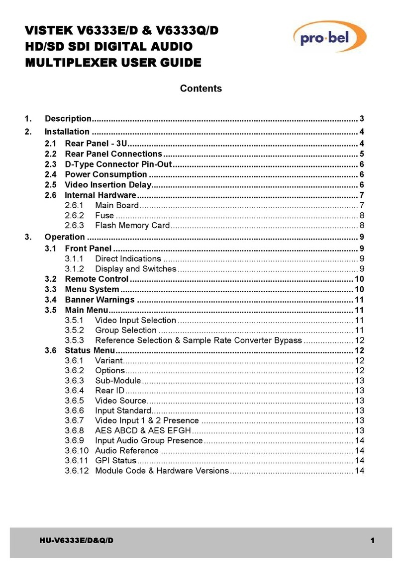
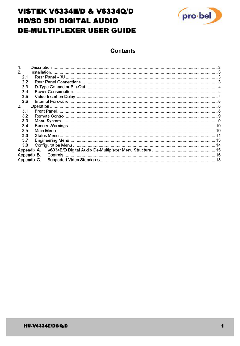
pro bel VISTEK V1633/A User manual

1
VISTEK V1633/A &V1633/D
AUDIOMULTIPLEXER
USERGUIDE
www.pro-bel.com

VISTEKV1633/A & V1633/D
sdi audiomultiplexer
2Issue 4
Contents
1. DESCRIPTION...........................................................................................................3
2. INSTALLATION.........................................................................................................4
2.1 Rear Panel – 3U...............................................................................................4
2.2 Rear Panel – 1U...............................................................................................4
2.3 Rear Panel Connections.................................................................................5
2.4 D-Type Connector Pin-out..............................................................................5
2.5 Power Consumption........................................................................................6
2.6 Insertion Delay.................................................................................................6
2.7 Module Installation..........................................................................................6
2.8 Internal Hardware............................................................................................6
2.8.1 Main Board....................................................................................................6
2.8.2 Analogue I/P Module....................................................................................7
2.8.3 DigitalI/PModule .........................................................................................7
3. OPERATION..............................................................................................................8
3.1 Front Panel.......................................................................................................8
3.2 Power................................................................................................................8
3.3 Remote Control................................................................................................8
3.4 Standard Indications.......................................................................................9
3.5 Module Indication............................................................................................9
3.6 Group Selections - D1.....................................................................................9
3.7 Reference Selection........................................................................................9
3.8 Internal Settings.............................................................................................10
3.9 Operating Modes...........................................................................................10
3.10 AncillaryBlanking..........................................................................................10
4. ADC INPUT MODULE.............................................................................................11
4.1 Description.....................................................................................................11
4.2 Max Input Level Setting.................................................................................11
Table 4.2.1.................................................................................................................11
4.3 Calibration......................................................................................................11
5. AES INPUT MODULE..............................................................................................12
5.1 Description.....................................................................................................12

VISTEK V1633/A & V1633/D
sdiaudiomultiplexer
HU-V1633/A&D 3
1. DESCRIPTION
The V1633A Audio Multiplexerisa full broadcast specification embedder ofaudio data into an SDI data
stream. It forms part of the VistekV1600 range of modular interface products. It isa 3U high card, which is
fitted into eitherthe 1U V1601 or 3U V1603 chassisfromwhich it receivesitspower. It isan improved and
upgraded replacement for the V1633. The main improvementsare a single board construction, and the
fitting ofaudio sub-boards. Thismeansthat either digital AES oranalogue inputs can be accepted. Fitting
one of two available sub-modulesmakes the choice. There is also an audio demultiplexer module, the
V1634A, which replacesthe V1634 and is fullycompatible with the V1633A.
In both the V1601 and V1603 racks passive rear modulesare required to interface to the outside world. For
each racktwo rear modules are available depending on whether the audio is required to be analogue, digital
AES balanced ordigital AES unbalanced. The rear modules are common forthe V1633A and V1634A.
The SDI video maybe D1 orD2 in either625/50 or 525/60 standard. The unit automaticallydetects the
standard and format ofthe input signal and operatesaccordingly.
Ifthe analogue input module hasbeen fitted then the inputsmust be balanced signals. Ifthe digital AES
input option isfitted then the AESsignalsare accepted as eitherbalanced or unbalanced, depending on the
type of rear module that isfitted to the rack.
The unit embedsaudio onto an SDI video data streamaccording to SMPTE 272M. Anyone ofthe available
audio groupsmaybe embedded; the number depends on whether the signal is D1 or D2. Unlike
multiplexersfromsome other manufacturersthe audio does not need to be synchronouswith the video into
which it isto be embedded. This makesthe use ofembedded audio within a studio area much simpler to
implement. Howeverit must be noted that some othermanufacturers de-multiplexerswill not accept
embedded audio ifit is asynchronousto the SDI clock.
Anotherfacilityto assist the installation in a realenvironment isthe abilityto resample an asynchronous AES
input to an external reference, generating synchronousmultiplexed audio. The external reference maybe a
Blackand Burst video, another AES signal, or the SDI video itself. With an ADC module, the sampling rate
is locked to whichever reference isselected.
There are three SDI outputsthat are re-clocked versionsof the SDI input. If the signalsare D1 then all
ancillarydata maybe stripped offthe SDI input signal priorto embedding. The EDH isregenerated on the
card. This facilityisnot available for D2 signals.
The unit is fullycontrollable over the DARTremote control system.
The output of the unit hasfull EDH signals applied, but there isno EDH detection on the input.

VISTEKV1633/A & V1633/D
sdi audiomultiplexer
4Issue 4
2. INSTALLATION
2.1 Rear Panel – 3U
Two 3U rear panel options are available, depending on the output format. Theyare shown below:
AES UNBALANCED
SDI
SDI1
SDI2
SDI3
VIDEO
REF
SDI
SDI1
SDI2
SDI3
L/AES
R
L/AES
R
AES
REF
VIDEO
REF
+
-
+
-
s
s
+
-
s
-
-
+
+AES A
AES B
AES
REF
ANALOGUE or
AES BALANCED
A
B
SDI
SDI1
SDI2
VIDEO
REF
Audio IO
D-TYPE
2.2 Rear Panel – 1U
AES UNBALANCED
ANALOGUE or
AES BALANCED
SDI
IN
SDI1
SDI2
SDI3
L/AES
R/AES
VID. REF
+
-s-
+
AB
DART
AES
REF
+
-s
L/AES
R/AES
+
-s-
+
SDI
IN
SDI1
SDI2
SDI3
VID. REF
DART
AES
REF
+
-s

VISTEK V1633/A & V1633/D
sdiaudiomultiplexer
HU-V1633/A&D 5
2.3 Rear Panel Connections
SIGNALCONN DESCRIPTION
SDI IN BNC SDI Video Input
SDI 1, 2, 3 BNC 3 off SDI Video Outputs
A, B Audio Inputsor ChannelsA and B
+,- Indicate the Positive and Negative of AESsignal
L/AESThe Left channel (analogue) orAES O/P 1 (digital)
R/AESThe Right channel (analogue) or AESO/P 2 (digital)
AES REF AES Reference Input
VID. REFBNC Video Reference Input
DARTRJ45 DARTNETconnection. Onlyused in one position in 1U rack
2.4 D-Type Connector Pin-out
The D type connectoron the unit isfemale.
Analogue Input
Pin Function Pin Function
1A Left In - 14 A Left In +
2GND 15 GND
3A Right In - 16 A Right In +
4GND 17 GND
5B Left In - 18 B Left In +
6GND 19 GND
7B Right In - 20 B Right In +
8GND 21 GND
9GND 22 GND
10 AES RefIn - 23 AESRefIn +
11 GND 24 GND
12 GND 25 GND
13 GND
AES Input
Pin Function Pin Function
1AES A In -14 AESA In +
2GND 15 GND
3N/C 16 N/C
4GND 17 GND
5AES B In -18 AESB In +
6GND 19 GND
7N/C 20 N/C
8GND 21 GND
9GND 22 GND
10 AES RefIn - 23 AESRefIn +
11 GND 24 GND
12 GND 25 GND
13 GND

VISTEKV1633/A & V1633/D
sdi audiomultiplexer
6Issue 4
2.5 Power Consumption
The power consumption ofthe V1633A depends on which output module isfitted and isshown in the
following table:
Base Unit :
~6W
Base Unit + Analogue I/O:
~9W
Base Unit + Digital I/O:
~7W
2.6 Insertion Delay
The video insertion delay, fromD1 I/P to D1 O/Pis 495µs.
2.7 Module Installation
One of the two available input modulesmust be fitted. The optionsare:
Analogue Input PCB130-2172
Digital Input PCB130-2182
The module fitsin the lowerright hand area ofthe PCB labelled ‘
INPUTMODULE’. Ensure the module is
inserted the right wayround, sothe component ident writing isthe OPPOSITE orientation as that on the main
board. It is not possible to fit one on the sub-boards meant for the companion V1634, but it is possible to fit
one of these boardsthe wrong wayround.
NOTE: Do not fit orremoveasub-module with the unitpowered. Ensure the module iscorrectlyfitted
before applying power.
When the unit ispowered, front panel LEDs indicate which type ofoutput module is fitted - ADC or AES.
2.8 Internal Hardware
2.8.1 Main Board
FRONT PANEL
REAR CONNECTOR
SUB-MODULE
PROM
DIL SWITCH
LK3
LK2
SW1
U8 FS1

VISTEK V1633/A & V1633/D
sdiaudiomultiplexer
HU-V1633/A&D 7
The significant itemson the main board are described here:
FS 1 Input power fuse, 3A.
SW1 Internalconfiguration switches, S1 at the top. See Section 3.8 for details.
Note that
U8 The PROM that contains the firmwareforthe programmable device. I the event
ofupgradesin the field it is most likelythat this is the devicethat will need to be
changed.
LK 2 Enables termination of the AESreference:
UP= Terminated
DOWN= Hi-Z
LK 3 Enables termination of the video reference:
UP= Hi-Z
DOWN= Terminated
Sub-Module Fitted with either the Analogue I/P Module (130-2170) or the digital I/P module
(130-2180). Check for correct orientation before powering the unit.
2.8.2 Analogue I/P Module
SW 1 Set MaximumINPUTLevel (MIL)for channel pairB
SW 2 Set MaximumINPUTLevel (MIL)for channel pairA
RV 1 Calibration trimchannel AL
RV 2 Calibration trimchannel AR
RV 3 Calibration trimchannel BL
RV 4 Calibration trimchannel BR
2.8.3 Digital I/P Module
There are no adjustments on the digital I/P module
SW2-A
RV1-AL
RV2-AR
RV3-BL
RV4-BR
SW1-B

VISTEKV1633/A & V1633/D
sdi audiomultiplexer
8Issue 4
3. OPERATION
3.1 Front Panel
1
REM +V
Local
Rem
V1633
Audio
Multiplexer
DART Control Access andPowerindicators
REMOTE/LOCAL controlselection
Standard and formatindication
D1
D2
Audio
525 625
1
23
4
Group Select
Audio output Status
Group Occupancy
ADCAES InputModule
Vid/SDI
DCT
AES ReferenceSelect
Group
1
3
2
4
12
3.2 Power
The power LED, marked +V, indicates that the 5VVCC power rail ispresent on the board. Thisshows not
onlythat power has been applied to the rear, but also that the on board regulator isfunctioning.
There is a fuse on the unit in series with the power input, and ifthishas‘blown’ then the +V LED will be OFF.
3.3 Remote Control
The V1633A can be controlled fromeither the front panel, shown above or through the DARTremote control
network. IfDARTisused then anyDART controller, with knowledge of the V1633A can be used. Vistekcan
provide eitherthe V1605 1U control panel or VIEWFIND, which isa PC based universal control system. Any
DARTcontroller can be used, provided it has‘knowledge’ on the V1633A.
The control source, Local orRemote, is selected bythe toggle switch on the front panel. The REM LED
does not indicate the selection of remote control, but ‘blips’ to showaccessbythe RackController, iffitted.
Onlythe position ofthe toggle switch indicatesthat remote control hasbeen selected.
The status LEDson the front panel are active forLocal or Remote control so always show the operating
condition.

VISTEK V1633/A & V1633/D
sdiaudiomultiplexer
HU-V1633/A&D 9
3.4 Standard Indications
FourLEDson the front panel show the standard and format ofthe input signal. The unit can operate in
either525/60 or 625/50 formats, each ofwhich can be component (D1) or composite (D2). Onlyone LED
can be on at anyone time.
Ifthere isno SDI video input then all fourofthese LEDswill OFF.
3.5 Module Indication
TwoLEDs are used to indicate which ofthe two availablesub-modules is fitted. Normallyjustone ofthese
LEDs will be ON. It ispossible that afuture module will provide one AESinput and one analogue input, a so-
called hybrid module; in this case both LEDswill be ON.
3.6 Group Selections - D1
With aD1 signal, there can up to four groupsofembedded audio, each group carrying two AES streams.
The V1633A can onlyembed on one ofthese groups selected using a front panel rotaryswitch with markings
1to 4.The switch should be used to indicate whichof the groups hasbeen selected and not the GROUP
LEDsabove. Audio can onlybe embedded on agroup which is has no audio on it. An option is available on
S1 Switch1, to blankall groups priorto embedding; this isan all ornothing selection. NOTE:Appending
audio onto an SDI sourcealreadycontaining audio data fromaminorityof othermanufacturersmultiplexers
which do not conformfullyto the SMPTEspec. maycauseproblemsifthe ancillarydata space is not pre-
blanked.
The ‘Group’ LEDs indicate which groups are occupied on the output signal, and not which group hasbeen
selected. Thus anynumberofthe LEDsmaybe ON. If there is an error on the input audio, or no signal is
present, the group light on the selected group will flash.
3.7 Reference Selection
Manyinstallationshavedifficultywith embedded audio, whichcan often be traced to the frequencyand
phase relationship between the video and AES audio. UnlikemanySDI De-multiplexersthe V1633A does
not require the signals to be synchronous.In fact it isquite possible for the SDI video and the two
multiplexed audio data streamsto have no defined relationship.
Toassist in operational installation the V1633A can be used to resample the audio to 48kHzwith respect to
various reference signals. Thismayhelp ifthe audio isto be de-multiplexed at alaterstage byanother
manufacturer’sde-multiplexer. The reference sourcemaybe either an AESsignal or avideo signal. The
video reference mybe eitherthe SDI input signal itselfor an external analogue black and burst reference.
The front panel hasa three-position selection switch used asfollows:
POSn Definition Description
VID/SDI Video Ref. and SDI I/P Use one ofthe video references. The choicebetween Ref.
and SDI is made byswitch 4 on the internal DIL switch. IfRef.
isselected but not present, then SDI will be used.
DCTDirect Pass AES without synchronisation.
AESAES Ref. Use the external AES as areference. If this is absent then the
SDI input will be used. An AESreference of48kHzmustbe
used.

VISTEKV1633/A & V1633/D
sdi audiomultiplexer
10Issue 4
3.8 Internal Settings
Switch Title Description LeftRight (= ON)
0 ANC BlankBlankall ancillarydata fromthe output BlankPass
1 Reserved
2 Reserved
3 A->A, A->B / A->A, B->BA-> both A->A,B->B
4* REF SDI Select video reference between Ext. Ref. and SDI EXT SDI
5 LSB 10
6 Op. Mode Select 1 of8 operating modes10
7 MSB (switch ON = 0, OFF = 1) 10
For normal operation all switchesshould be set to the right (ON).
* The sense of thisswitch wasincorrectly stated in earlier versionsof this manual.
3.9 Operating Modes
Three operating modeshave been incorporated into the V1633A. Mode 0isafull SMPTEspecification,
allowing synchronous orasynchronousmultiplexing, i.e. the AES inputs need not be locked to the SDI or
eachother when operating in DireCTmode (in Video or AESreference mode the audio isautomatically
synchronised).
Howeverbecausesomede-multiplexerson the market makecertainassumptions about the multiplexed
data. For these systems two other modeshave been incorporated.
In anyone line ofvideo there maybe 3 or 4 samples ofaudio data fromeach AES stream. Mode 1 forces the
number ofsamplesfrom each channel to be the samei.e. 3from Aand 3from B, or 4from Aand 4from B;
a combination isnot allowed in this mode.
Mode 2isabasicoperating mode, which isentirelysynchronous, and doesnot insert control packets,
suitable for basic de-multiplexers types.
Mode Description
0 Full SMPTE spec. Audio embedding, D1 / D2.
1 AES channelsA &B packetsaligned
2 BasicEmbedding, no Control Status. No asynchronouscapability
3 = mode 0
4 = mode 1
5 = mode 2
6 = mode 0
7 = mode 1
3.10 AncillaryBlanking
Ifthe SDI into the V1633A hasaudio alreadyembedded on the selected group, it isnecessaryto remove any
data alreadyin the ancillarydata space, or select anothergroup (see Section 3.6) This can be done by
setting S0 ofthe internal DIL switch accordingly. This can also be set over the remote control.
Ifthe Ancillarydata isset to be blanked then ALL data in the ancillaryspace will be removed, not just the
audio data.

VISTEK V1633/A & V1633/D
sdiaudiomultiplexer
HU-V1633/A&D 11
4. ADC INPUT MODULE
4.1 Description
The 130-2172 dual ADC input modulefeatures24-bit ADCsto accommodate future upgrade to 24 bit
embedding in the SDI. Each channel pair-consisting of Land Rchannels-has digitallycontrolled MIL
which maybe adjusted from+12dBu to +24dBu bythe on-board hexswitchesSW1 band SW2.
4.2 Max Input Level Setting
The MIL ofeach of the two channel pairsAand Bmaybe set from+12dBu to +24dBu in 1dB steps by
means ofthe on-board hexswitchesif the V1633 isoperated in local mode. HexswitchSW1and SW2
control MIL ofchannelpairAand Brespectivelyand Table 4.2.1 belowshowsthe MIL settingsforeach hex
switch position. The factorysupplied shipping setting is+18dBu.
Ifthe V1633 is connected to aDARTcompatible remote hostand operated in remote mode, the MIL maybe
set remotelyand the on-board hex switches are disabled.
Table 4.2.1
Switch Setting MOL
0+12dBu
1+13dBu
2+14dBu
3+15dBu
4+16dBu
5+17dBu
6+18dBu
7+19dBu
8+20dBu
9+21dBu
A+22dBu
B+23dBu
C+24dBu
others+24dBu
4.3 Calibration
The 130-2172 ADC output module hasfourtrimming potentiometersRV1, RV2, RV3 and RV4, which
respectivelytrimthe gain of the module’sdigitallycontrolled gain blockfor analogue inputs AL, AR, BL and
BR. These potentiometers should not requireadjustment bythe user, as theyareaccuratelyset at the
factory.

VISTEKV1633/A & V1633/D
sdi audiomultiplexer
12Issue 4
5. AES INPUT MODULE
5.1 Description
The 130-2182 AESinput module hasdual AES inputs which, depending on the reference mode selected,
mayeither locked to SDI, external Black and Burst video or AESreferencesource, or passed without
resampling in DireCTmode.
Ifthe external Black and Burst video reference isselected, the unit will automaticallysynchroniseto 525 /60
or 625/50 Black and Burst video input to the VID REF connector on the rear panel. Ifthe external 48kHzAES
referenceis selected, the unit will frequencylock both AES output streams to the external AES applied to the
AESREF connector on the rearpanel, and will time-align AES input framesand channel statusblocksto
those ofthe external AES reference.
Ifthe selected referencesourceisdisconnected orfails,the unit will automaticallydefault to the internal SDI
reference.
This manual suits for next models
1
Table of contents
Other pro bel Multiplexer manuals
Popular Multiplexer manuals by other brands

Analogic
Analogic DBS 8700 Hardware user manual

Elcon
Elcon MUX 2700 instruction manual

System Q
System Q CCT287 instruction manual

AD-net Technology
AD-net Technology AN-TDM-IP-1E1/2E1-A user manual

Beijing Huahuan Electronics
Beijing Huahuan Electronics H9MO-1641S user guide

Alcatel-Lucent
Alcatel-Lucent 1643 AMS Operation manual