Ganz Thermal PT Thermal Series User manual

PT Thermal Series Quick Start Guide December 2013
Document Number: 1018264, Revision A
©Copyright 2013, CBC AMERICA, Corp. - All rights reserved. The contents of this document may not be reproduced in whole or in part without the written
consent of the copyright owner.
Important Safety Instructions
1. Read these instructions.
2. Keep these instructions.
3. Heed all warnings.
4. Follow all instructions.
5. Install in accordance with the manufacturer’s instructions.
6. Do not defeat the purpose of the polarized or grounding-type plug.
A polarized plug has two blades with one wider than the other. A
grounding type plug has two blades and a third grounding prong.
The wide blade or the third prong is provided for your safety. If the
provided plug does not fit into your outlet, consult an electrician for
replacement of the obsolete outlet.
7. Use only with the tripod or bracket specified by the manufacturer, or
sold with the apparatus.
8. Installation of the equipment must comply with local and national
electrical codes.
9. This product must be connected to a Power Over Ethernet IEEE
802.af compliant power source or a UL Listed “Class 2” power supply
rated 12-24 V DC or 24 V AC minimum 13 W or 0.54 A.
10. Operating the camera at voltage levels outside the specified range
may result in permanent damage to the unit and void the product
warranty.
11. Clean the camera lens only with Kodak lens cleaning paper.
12. Failure to follow the proper procedure may cause permanent
damage to the camera and void the product warranty.
WARNING
DEVICE SENSITIVE TO ELECTROSTATIC DISCHARGE
The camera electronics and electronic interfaces are sensitive to
electrostatic discharge. Please follow appropriate ESD procedures when
handling the camera and during installation. For PoE installations, CBC
AMERICA strongly recommends the use of STP cabling and an earth
grounded end point to ensure proper ESD immunity. For AC or DC
powered installations, a properly earth grounded power source is strongly
recommended.
CAUTION
To ensure a proper earth ground (between the GANZ THERMAL camera
and a PoE switch) CBC AMERICA strongly recommends the use of Shielded
Twisted Pair (STP) cabling. Installations of GANZ THERMAL cameras using
a STP cabling and a properly earth grounded PoE switch are tested to
comply with industry immunity standards for Electro Static Discharge.
Any other installation method may leave the camera at risk and void the
warranty.

PT Thermal Series Quick Start Guide December 2013
2
www.ganzsecurity.com
Important Legal and Regulatory Information
Legal Consideration
ALL STATEMENTS, INFORMATION, AND RECOMMENDATIONS IN THIS
MANUAL ARE BELIEVED TO BE ACCURATE BUT ARE PRESENTED WITHOUT
WARRANTY OF ANY KIND. NOTWITHSTANDING ANY OTHER WARRANTY
HEREIN, ALL DOCUMENT FILES AND SOFTWARE ARE PROVIDED “AS IS”
WITH ALL FAULTS. GANZ THERMAL DISCLAIMS ALL WARRANTIES,
EXPRESSED OR IMPLIED, INCLUDING, WITHOUT LIMITATION, THOSE OF
MERCHANTABILITY, FITNESS FOR A PARTICULAR PURPOSE AND
NONINFRINGEMENT OR ARISING FROM A COURSE OF DEALING, USAGE, OR
TRADE PRACTICE. IN NO EVENT SHALL CBC AMERICA BE LIABLE FOR ANY
INDIRECT, SPECIAL, CONSEQUENTIAL, OR INCIDENTAL DAMAGES,
INCLUDING, WITHOUT LIMITATION, LOST PROFITS OR LOSS OR DAMAGE
TO DATA ARISING OUT OF THE USE OR INABILITY TO USE THIS MANUAL,
EVEN IF CBC AMERICA HAS BEEN ADVISED OF THE POSSIBILITY OF SUCH
DAMAGES
Export Control:This document contains technology controlled under the
U.S. Export Administration Regulations (EAR),diversion contrary to
U.S. Law is prohibited.
Regulatory
This product has been tested and found to comply with the limits
of FCC Class A Part 15 Subpart B and CES-003.
RoHS
This product complies with the European ROHS directive.
Introducing Ganz PT Thermal
This document provides information about Ganz Thermal Series, a Pan &
Tilt, Fixed Focal Length Infrared Camera. You can download all required
documents including the more detailed user manual at
www.ganzsecurity.com. The camera system is an Internet Protocol (IP)
networked solution that conforms to the Open Network Video Interface
Forum (ONVIF™) and also offers analog video output (NTSC/PAL).
What’s in the Box
Ensure that you have the following package contents:
•Ganz PT Thermal
•Ganz PT Thermal Top Hat
•Hardware Kit
o1 - Cable Sealing Gland with electrical nut
o1 - O-Ring
o1 – 4-pin power block
•Quick Start Guide (this guide)
•End User Licensing Agreement (EULA)

PT Thermal Series Quick Start Guide December 2013
3
www.ganzsecurity.com
Ganz PT Thermal
Ganz PT Thermal Top Hat
Installing the PT Thermal Camera
You will need the following items (not included) before you can install the
IP Camera (recommended tool list)
•Power source: PoE Switch, 12-24V DC or 24V AC
•IP Network
•Ethernet Cable (STP Cat5 required)
•Mounting bracket
•Flat-head screwdriver
•2 Open End Wrenches – 1 inch (25mm), OR adjustable wrenches
•A 6-inch scale OR ruler
•Screwdriver (if electric, set to 16 inch-pounds of torque) with a
T20 Torx bit
•RJ-45 connecter
•RJ-45 Crimping Tool
•Suggested Tools for Analog Video:
oCoax Cable
oCoax Cable Cutter/Stripper
oBNC Connector
oBNC Crimping Tool
Prepare Cables and Gland
1. Slide all needed cables through the bottom of the top hat.
2. Remove electrical nut from the cable gland and place the orange
O-ring on the threaded side of the cable gland.
3. Secure cables through the cable gland for IP66 installation by
using one of the below procedures:
Securing for IP66 (POE only)
1. Slide the Ethernet cable through the threaded end of the cable
sealing gland, with Orange O-Ring installed.

PT Thermal Series Quick Start Guide December 2013
4
www.ganzsecurity.com
2. Measure approximately 5 inches of cable slack from the end of the
cable to the rubber grommet of the sealing gland. Use a scale to
measure the length.
3. Attach one open end wrench onto the flange of the cable gland
and tighten the compression nut, with the second open wrench, to
approximately 50-55 in-lbs. of torque
4. Assemble a new RJ45 head to the Cat 5 Ethernet Cable
Securing for IP66 (Ethernet & AC/DC power):
1. Slide the Ethernet cable through the threaded end of the cable
sealing gland, with O-Ring installed.
2. Slide the 2, 20 AWG power wires through the back side of the
cable sealing gland.
3. Measure approximately 5 inches of cable slack from the end of the
cable to the rubber grommet of the sealing gland. Use a scale to
measure the length.
4. Attach one open end wrench onto the flange of the cable gland
and tighten the compression nut, with the second open wrench, to
approximately 50-55 in-lbs. of torque.
5. Assemble a new RJ45 head to the Cat 5 Ethernet Cable.
6. Assemble a mating power connector to the 2 AC or 2 DC power
cables.
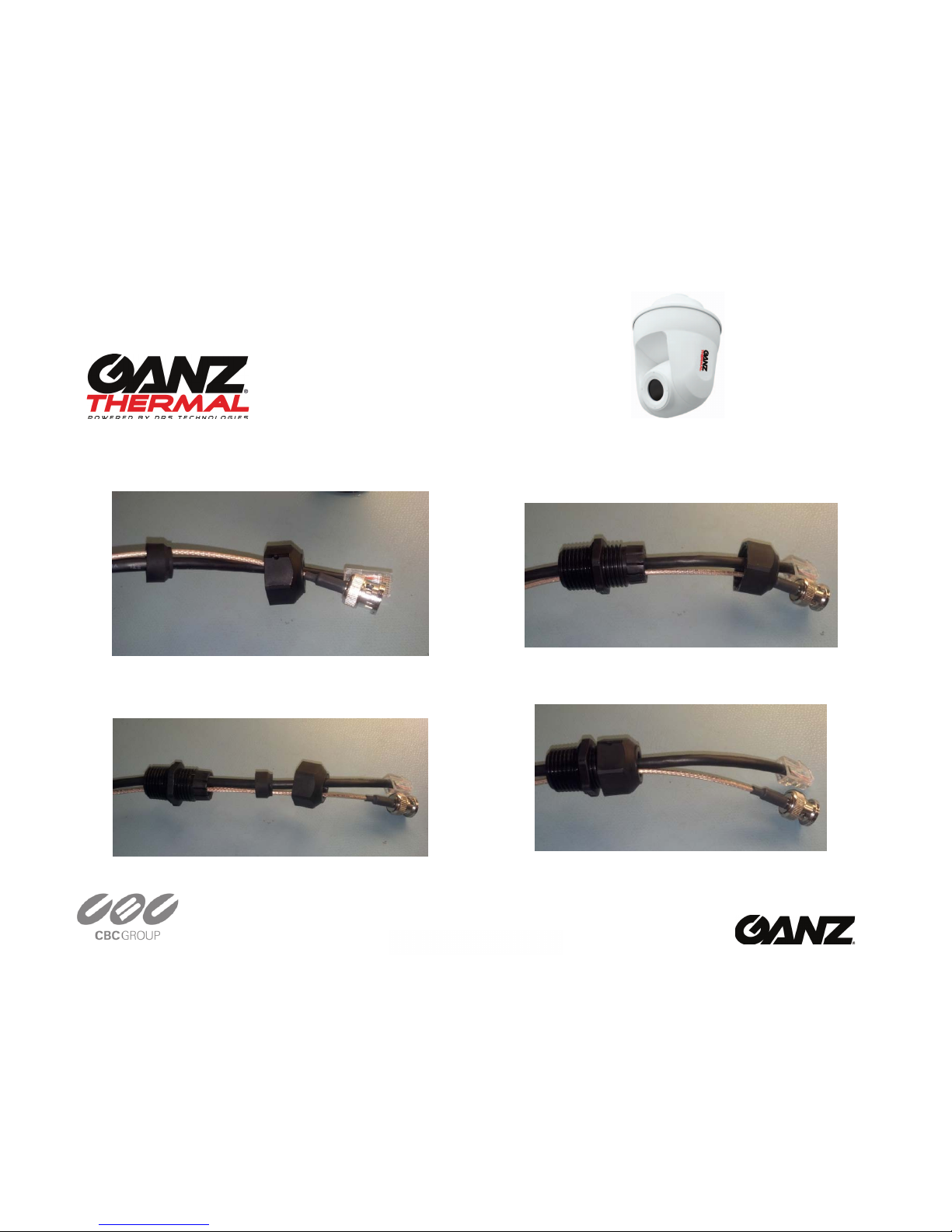
Securing for IP66 (Analog & AC/DC Power)
1. Slide the Coax cable through the threaded end of the cable sealing
gland, with O-Ring installed.
2. Slide the 2, 20 AWG power wires (and any RS-485 wires) through
the back side of the cable sealing gland.
3. Measure approximately 5 inches of cable slack from the end of the
cable to the rubber grommet of the sealing gland for the power
wires and approximately 10 inches of cable slack for the analog
cable. Use a scale to measure the length.
4. Attach one open end wrench onto the flange of the cable gland
and tighten the compression nut, with the second open wrench, to
approximately 50-55 in-lbs. of torque.
5. Assemble a new BNC connector to the Coax Cable.
6. Assemble a mating power connector to the 2 AC or 2 DC power
cables (and RS-485 cables if used).
Securing for IP66 (Analog & Ethernet)
1. Put the nut onto the cables first. And then push the analog video
cable (RG179BU required for this configuration) and CAT5 cable
through the gland. The CAT5 cable goes through the center. The
analog video goes through one of the 5 outer holes.

PT Thermal Series Quick Start Guide December 2013
5
www.ganzsecurity.com
2. Push the gland housing over the cables
3. Push the gland rubber into the gland housing
4. Tighten the gland nut onto the gland housing. Leave about 5
inches of cable sticking out of the gland housing

PT Thermal Series Quick Start Guide December 2013
6
www.ganzsecurity.com
5. Insert the cable and gland into the camera. Connect the Analog
cable and CAT5 cable to the camera. Slide the gland housing-to-
chassis nut over the cables. Tighten the gland housing-to-chassis
nut into the camera
6. Not shown, crimp the other end of the cables in place (not
shown).
For All Configurations
1. Pull the cable(s) taut back through the top hat, exposing the
thread of the cable sealing gland through the bottom of the top
hat.
2. Assemble the Electrical Nut back onto the gland and tighten the
Nut securely until it is finger tight. Use a flat head screwdriver to
continue turning the electrical nut until it reaches approximately
50 in-lbs of torque.
Wiring & Assembling the PT Thermal Camera
1. Connect the cable(s) to the respective connector:
a. Ethernet: Ethernet Port
b. Analog: Analog Video Out
i. To ensure a proper fit for RG6 or RG59 coax
cable, loop the excess cable slack along the
bottom of the top hat and then connect the
cable to the Analog Video Out port.
c. AC/DC Power: Connect wires to power block:
2. If powering the camera with an AC supply, connect AC+ to the
24VAC input and the AC- to the other 24VAC input
3. If powering the camera with a DC supply, connect the DC+ to the
12VDC input and the DC- (or ground) to the GND input.
4. RS-485: Connect wires to RS-485 Block.
a. Connect the RS-485+ pin to the camera’s POS and
connect the RS-485- pin to the camera’s NEG pin and the
RS-485 Ground to the camera’s GND.
5. Reconnect Power to the existing cable(s).
6. Check for Solid LED on the Ethernet connector to acknowledge
connectivity to the IP network. The status LED indicators are:
a. Solid Amber for 10MB connection
b. Solid Green for 100MB connection or Flashing Green for
Activity

PT Thermal Series Quick Start Guide December 2013
7
www.ganzsecurity.com
Ganz PT Thermal Connections and Pin-Out
7. Attach the top hat to the Ganz PT Thermal and secure with the
attached four screws using a screwdriver with a T20 Torx bit to
approximately 16 in-lbs. of torque.
Mounting the Ganz PT Thermal Camera
1. Attach the camera to the strain relief wire on the wall mount by
placing the loop of the wire through the hook of the top hat. This
will support the weight of the camera for the rest of the
installation.
2. Align the screw heads of the top hat with holes in the mount and
push the camera up to insert the screw heads. Turn the camera to
the right to lock the camera in place.
3. Secure the camera with the attached screws on the mount. Refer
to mount directions for specific instructions on the required bit and
torque.
Ganz PT Thermal Camera mounted on
a Standard Wall Bracket (WMK3-1W).

PT Thermal Series Quick Start Guide December 2013
8
www.ganzsecurity.com
Accessing the PT Thermal Camera Web Page
After installing the Ganz PT Thermal Camera, you will need to access the IP
Camera via its Web Page to make configuration changes and view live
video using the GANZ THERMAL Web Interface. In order to make these
changes, you can connect to the IP Camera from any PC on your network.
The PC must meet below requirements:
•OS - Microsoft Windows 7 or Windows XP or Windows Vista
•Internet Explorer 9.0 or Mozilla Firefox 8.0
•VLC Media Player Software 2.0.0 – can be downloaded from the
GANZ THERMAL Camera directly through the GANZ THERMAL Web
Interface or from http://www.videolan.org/vlc/
Device Discovery
•From Windows 7, click on Start > Computer > Network
•A list of devices connected to your network will appear
•Should DHCP fail, the camera will assign itself an IP address of
192.168.0.200 and a subnet mask of 255.255.255.0
Login to the PT Thermal Camera Web Page
For Windows 7 OS, double click on the name of the Camera from the
Device Discovery interface. For other Operating Systems, login to the
router, find the attached PT Thermal Camera and find its IP address.
Enter the IP address of the IP Camera on the Browser URL line.
A login screen will appear. Enter the default username and password (case
sensitive).
Username: admin
Password: 1234
If you have not downloaded the VLC Media Player, you can download
from the PT Thermal Camera. After login to the IP Camera, follow the
prompt at the bottom of the screen to install the VLC Media Player.
Viewing Live Video
Once you have successfully logged in
to the IP Camera, live video image
can be seen on the Browser.
Congratulations!! Ganz PT
Thermal Camera Installation and
Configuration is now complete.

PT Thermal Series Quick Start Guide December 2013
9
www.ganzsecurity.com
For More Information
Category
Online Location
Ganz Thermal PT Camera Series
Documentation
www.ganzsecurity.com/manuals
Ganz Thermal PT Camera Support
VLC Media Player
www.ganzsecurity.com/support
http://www.videolan.org/vlc/
Table of contents
Popular Thermal Camera manuals by other brands

Mikron
Mikron 7600 quick start

D-Link
D-Link DCS-9500T Quick installation guide

MARTINDALE
MARTINDALE IRC327 instruction manual

Planck VISION SYSTEMS
Planck VISION SYSTEMS PROTECTOWIRE PWTC100 Quick start manual

HIK VISION
HIK VISION DS-2TP31B-3AUF How to configure

HIK VISION
HIK VISION DS-2TD2537T-4/Q quick start guide