22
WARNING: Read all instructions!
Failure to follow all instructions listed
below may result in, fire and/or serious injury.
This product should not be operated by those
who are unfamiliar with the manual.
Save these instructions and forward the
product only together with this instruction
manual.
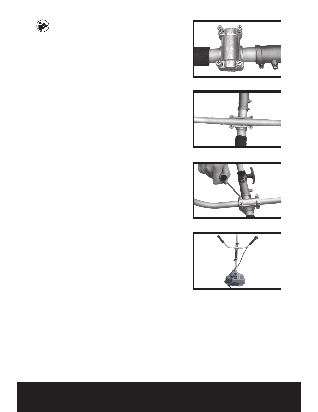
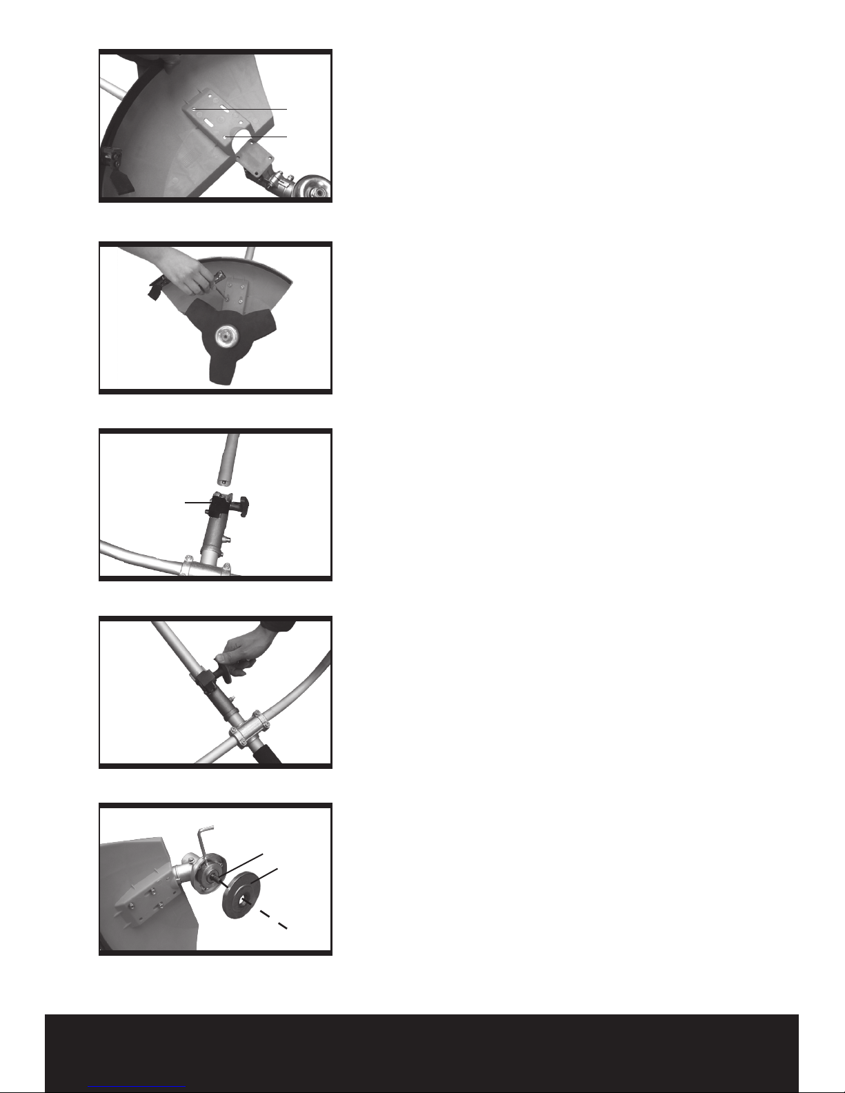
This product is intended for cutting grass and
small bushes.
SAVE THESE
INSTRUCTIONS
SAFETY INSTRUCTIONS
1. Keep people away form work area.
This product shall be used only by competent
adults who have fully read and understood this
manual. The cutter may expel objects; keep
children, animals and bystanders at least 50
feet (15meters) away from work area. Do not
allow children or untrained individuals to use this
unit. Keep all parts of your body away from any
moving part.
2. Personal safety
Always wear suitable safety equipment to
protect your eyes, ears, hands, legs and feet.
Tie back long hair. Switch off engine before
examining or clearing the cutting head.
3. Clothing
Wearing protective clothing also reduces this
risk and severity of injury from thrown debris
or contact with the cutting attachment. Wear
the cutter harness, gloves, a long sleeved shirt,
long pants, and sturdy boots with nonlip soles.
Adjust the tool harness so that the machine
feels comfortable and well balanced.
4. Look after the cutter
When not in use, store in a dry, high place or
keep locked up out of children’s reach.
5. Check before use
Before use always ensure that the tool is not
damaged, if in doubt contact the helpline.
6. Do not operate this unit when you are
tired, ill, or under the influence of alcohol,
drugs, or medication.
A moment of inattention while operating the
cutter may result in serious personal injury.
7. Keep away from cutting blade
Even after the engine has stopped, the cutting
blade will spin for several seconds.
Please wait until the engine and cutting head
has fully stopped before putting the machine
down or accessing the blade area.
8. Turn the engine off when not trimming
If you stop cutting trimming for any reason,
always stop and switch off the engine. Never
leave the machine running and unattended.
9. Working environment
Objects thrown by the trimmer can cause
serious injury. Before operating the trimmer,
carefully inspect the area and remove any
broken glass, pieces of wire, and other loose
objects – which can be thrown or entangled in
the cutting head. A fire extinguisher must be
available for use near by. Do not operate in poor
light conditions.
10. Use the product only for its intended
purpose as described.
Do not overreach as this can result in loss of
balance or exposure to hot surfaces. Keep
proper footing and balance at all times. This
enables better control in unexpected situations.
11. Exhaust danger
Never operate petrol engines indoors or in
confined spaces. Pay special attention to
doorways and air conditioning inlets. Do not
allow the exhaust gases to enter buildings. Do
not allow the exhaust gases to enter buildings,
the exhaust gases fumes contain noxious fumes
and these fumes can lead to poisoning. Do not
touch areas around the exhaust or cylinder as
these parts become very hot during operation.
12. Repairs
For your safety repairs should be carried out
by a qualified person. Contact the helpline for
details of approved service agents.
13. Fuel Safety.
WARNING: This product requires
unleaded petrol and 2-stroke oil, ratio
30:1.
a) Always handle fuel with care. It is highly
flammable.