Phone Orders: 1-800-427-3363 • Customer Service: 1-800-876-5520
Figure 9
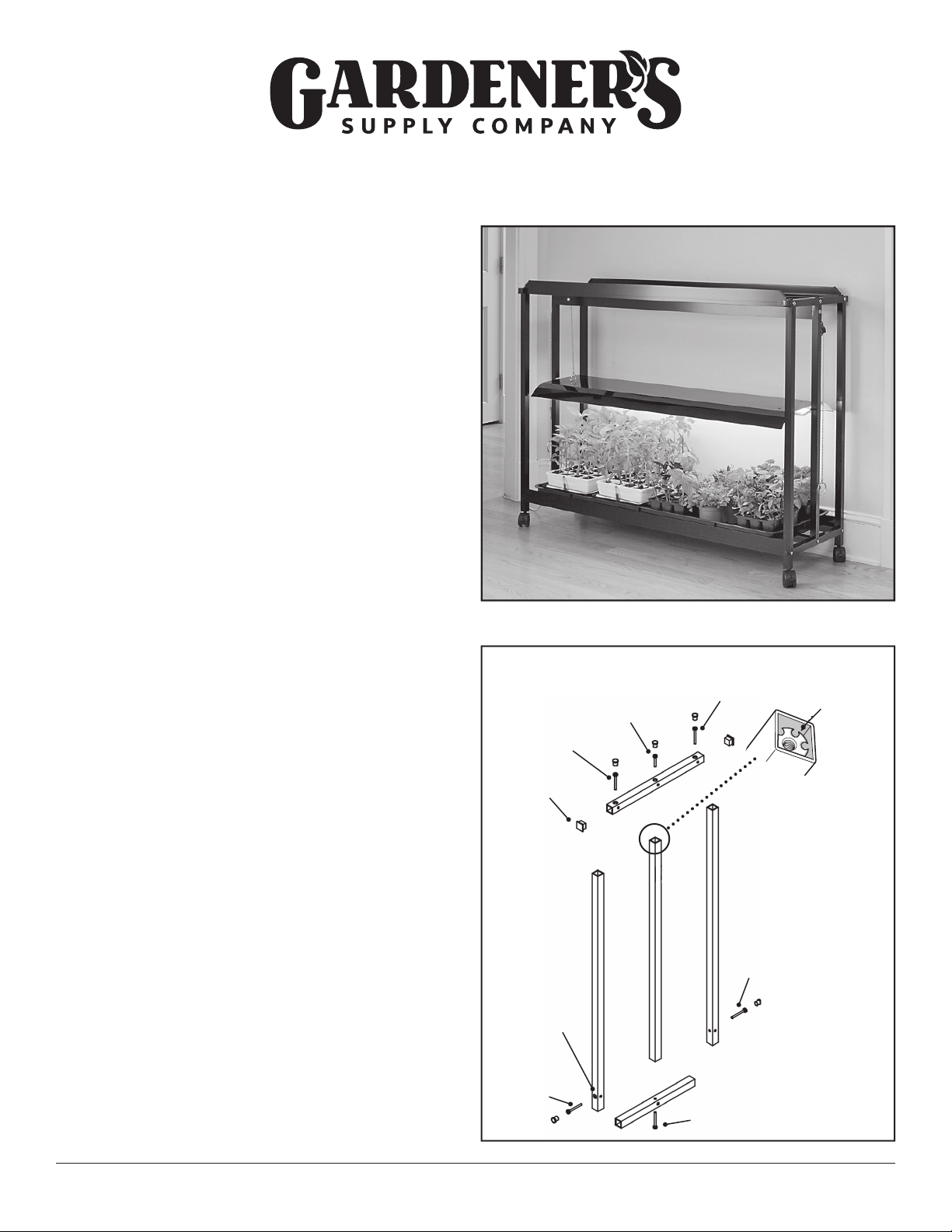
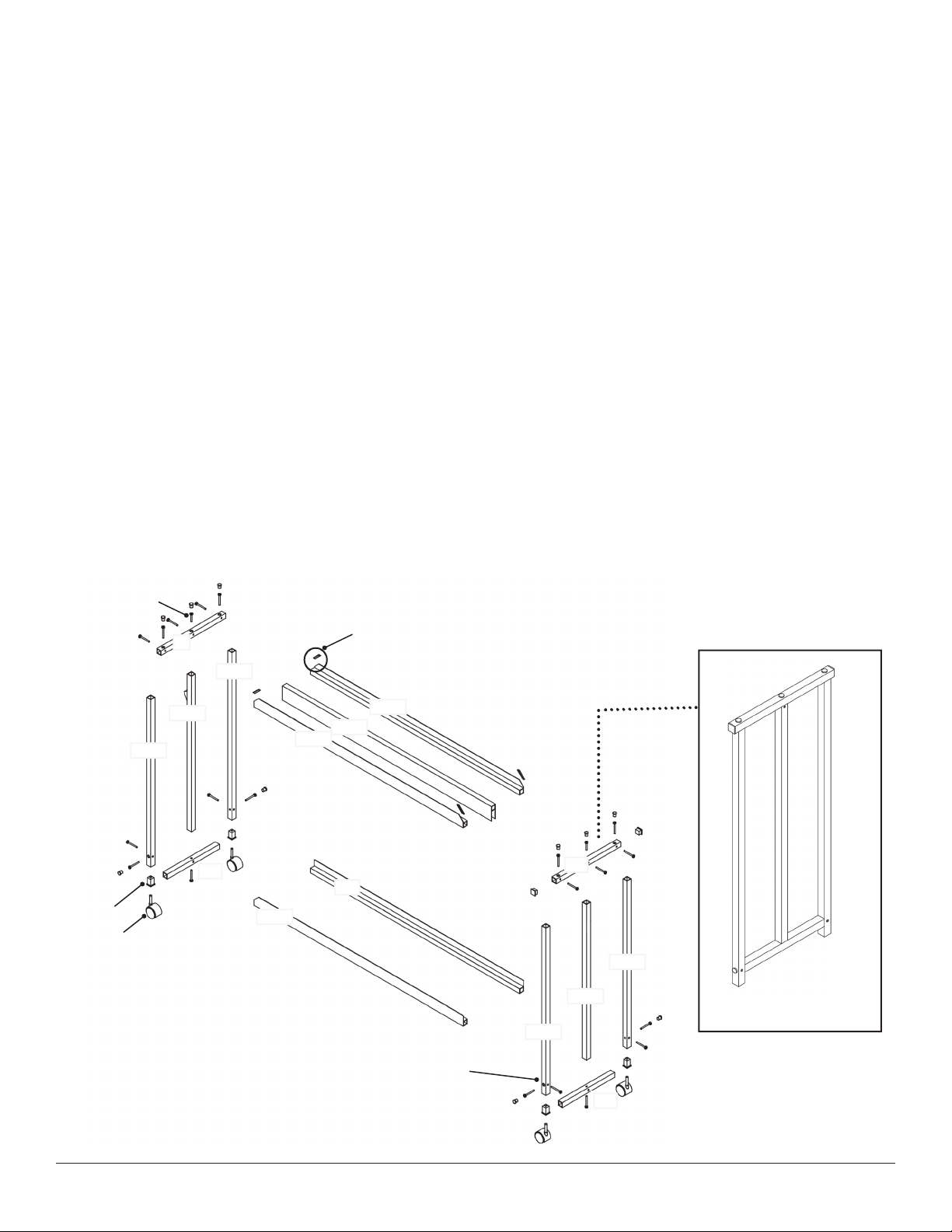
A1 Side
Frame
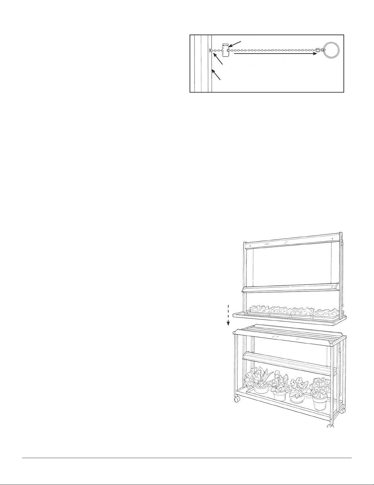
Chain Grip
Guide Hole
Pull chain in a horizontal direction.
Fluorescent Bulb Care and Disposal
To ensure maximum light output, clean the fluorescent tubes monthly with
a soft dry cloth.
The light intensity of fluorescent bulbs diminishes over time. When it’s time
to replace your bulbs, please dispose of them safely at your recycling center.
T- Fluorescent Bulbs contain Mercury and must be disposed in accordance
with Disposal Laws. See www.lamprecycle.org or call --- for
disposal information.
Adjusting the Fixtures
Step 1. Check the Ball Chains to make sure they are correctly
positioned and move freely through the Chain Grips when
pinched. Important: Support the Light Fixture with one hand
when pinching the Chain Grips.
Step 2. Adjust the height of the Light Fixture one side at a time by
pulling the chain out of the Chain Grip with the least amount of
resistance, as shown in Figure . Important: While supporting
the Fixture with one hand, be sure the Chain Grip firmly catches
the chain before removing your support.
Fixture Use and Safety
• Always turn off the power to the Light Fixtures when inserting, adjusting or removing Light Tubes. If you insert a Light Tube
when the power is on, it may trigger an auto safety mechanism, resulting in the light shutting off. If this happens, turn off the
Fixture; make sure the Light Tubes are fully seated in the tube sockets; wait for thirty () seconds, then turn the Fixture on
again. This will reset the Light Fixture so the lights operate normally.
• Use the power cord only with a properly grounded electrical outlet or power strip. Do not use with a two-plug outlet or
extension cord unless the adapter you use is properly grounded.
• If water is spilled near the power source, unplug the unit before you wipe up the water.
• Do not put objects on top of the Frame or on Light Fixture.
• For best results, attach a timer to your lights to control the length of time the lights are on and to be sure your plants get
adequate light.
• For on/off manual control of your lights, use the switch located on the power cord.
The Tabletop SunLite® Garden rests
directly on top of the Floor Model.
Combining a Tabletop SunLite Garden and
Floor Model SunLite Garden
You get double the growing space and greater mobility when
you combine the Tabletop (sold separately) with the Floor Model
SunLite®Garden. If you have previously purchased a Table Top
SunLite®Garden, combining the two models is easy.
Step 1. Assemble both units first, using the instructions provided.
Step 2. Remove the Poly Tray from the top of the Floor Model.
Step 3. Remove the rubber Corner Guards from the top four corners
of the Floor Model.
Step 4. Place the Tabletop directly on top of the Floor Model,
making sure the power on cord on each unit is hanging off the
same end, then replace the Tray. That’s all there is to it!
For articles and tips on seed starting and growing under lights, plus seed-starting systems and supplies,
please visit us at www.gardeners.com.