Gardol GBD-46R User manual

1
petrol lawn mower
original operating instructions
models:
GBD-46R (DYM1676CE-3)
GBD-46REV (DYM1676SED-3)
GBD-51REV (DYM1678SD-3)
GBD-51R (DYM162601)
Manufacturedby
Ningbo Daye Garden Machinery Co., Ltd.
No.58 Jinfeng Road
Yuyao, Zhejiang 315403
P.R. China
Importedby
Daye Europe GmbH
Parkstraße 1a
66450 Bexbach
Germany

2
WARNING:
For your own safety, please read this manual before attempting to operate your
new unit. Failure to follow these instructions can result in serious personal injury.
Spend a few moments to familiarize yourself with your mower before each use.
Keep this manual in a safe place, so that the information is available anytime. If
you give the equipment to any other person, hand over these operating
instructions and safety regulations as well.
Intendeduse
The equipment may only be used for the purpose it is designed for. Any other use is deemed to be a case of
misuse. The operator, and not the manufacturer, will be liable for any resulting damage or injuries of any kind.
The petrol lawn mower is intended for private use, i.e. for use in home and gardening environments.
Private use of the lawn mower refers an annual operating time up to of 50 hours, during which time the machine
is primarily used to maintain small-scale, residential lawns and home/ hobby gardens. Public facilities, sportis
grounds and agricultural or forestry applications are excluded.
Please note that our equipment has not been designed for use in commercial, trade or industrial applications.
Our warranty will be void if the machine is used in a commercial, trade or industrial business or for equivalent
purposes.
The operating instructions as supplied by the manufacturer must be kept and referred to in order to ensure that
the lawn mower is properly used and mainteed. The instructions contain valuable information on operating,
maintenance and servicing conditions.
Important! Due to the high risk of body injury to the user, the lawn mower may not be used to trim bushes,
hedges or shrubs, to cut scaling vegetation, planted roofs or balcony-grown grass, to clean (suck up) dirt and
debris off walkways, or to chop up tree or hedge clippings. Moreover, the lawn mower may not be used as a
power cultivator to level out elevated soil pieces such as molehills.
For safety reasons, the lawn mower may not be used as a drive unit for other work tools or toolkits of any kind.

3
CONTENTS
SECTION .1 SYMBOLS MARKED ON THE PRODUCT 4
SECTION 2 GENERAL SAFETY RULES 4
SECTION 3 PARTS DESCRIPTION 7
SECTION 4 TECHNICAL DATA 8
SECTION 5 ASSEMBLY 9
SECTION 6 “3 IN 1” 12
SECTION 7 OPERATING INSTRUCTIONS 13
SECTION 8 MAINTENANCE INSTRUCTIONS 20
SECTION 9 LUBRICATION INSTRUCTIONS 21
SECTION 10 CLEANING 21
SECTION 11 CHARGING THE STARTER BATTERY 23
SECTION 12 STORAGE INSTRUCTIONS (OFF SEASON) 24
SECTION 13 TROUBLESHOOTING 26
SECTION 14 WARRANTY 27
SECTION 15 ENVIRONMENT 28
SECTION 16 EC-DECLARATION OF CONFORMITY 29
WARNING:
For your own safety please read this manual before attempting to operate your new unit. Failure to follow
instructions can result in serious personal injury. Spend a few moments to familiarize yourself with your mower
before each use.
When you unpack the lawn mower, pay close attention not to twist or bend the cables and not to
pull the appliance on the cords. That may lead to irreversible damages that are not subject to
warranty.

4
1. SYMBOLS MARKED ON THE PRODUCT
B1 Read operating instructions.
B2 Keep bystanders away.
B3 Risk of injury to hands and feet.
B4 Flammable fuel. Keep fire away. Do not add fuel on running
machine.
B5 Toxic fumes. Don’t operate in closed rooms.
B6 Wear glasses and ear plugs during operation.
B7 High-current electric ignition circuit. Remove spark plug for
maintenace.
B8 Caution: Engine hot.
Sharp knives can cause severe injuries or even amputate limbs.
KEEP HANDS AND FEET AWAY.
Warning: Keep the safety signs clear and visible on the equipment. Replace the safety signs if they are missing
or illegible.
2. GENERAL SAFETY RULES
Your safety and the safety of others are very important. We have provided important safety messages in this
manual and on the engine. Please read these messages carefully.
A safety message alerts you to potential hazards that could hurt you or others. Each safety message is
preceded by a safety alert symbol and one of three words: DANGER, WARNING or CAUTION.
These signal words mean:
DANGER: You WILL be KILLED or SERIOUSLY HURT if you don't follow instructions.
WARNING: You CAN be KILLED or SERIOUSLY HURT if you don't follow instructions.
CAUTION: You CAN be HURT if you don't follow instructions.
Each message tells you what the hazard is, what can happen, and what you can do to avoid injury.
WARNING: When using petrol tools, basic safety precautions, including the following, should always be
followed to reduce the risk of serious personal injury and/or damage to the unit. Read all these
instructions prior to operating this product and retain these instructions for future reference.
WARNING: This machine produces an electromagnetic field during operation. This field may, under some
circumstances, interfere with active or passive medical implants. To reduce the risk of serious or
fatal injury, we recommend persons with medical implants to consult their physician and the
medical implant manufacturer before operating this machine.
F
igure 1: Symbols marked on the rear cover
F
igure 2: Safety label

5
Training
●Read the instructions carefully. Be familiar with the controls and the proper use of the equipment.
●Never allow children or people unfamiliar with these instructions to use the lawn mower. Local
regulations may restrict the age of the operator.
●Never mow while people, especially children, or pets are nearby.
●Keep in mind that the operator or user is responsible for accidents or hazards occurring to other people
or their property.
●The operators must receive proper training in the use, adjustment and operation of the machine,
including prohibited operations.
Preparation
●In operation, always wear sturdy footwear and long trousers. Do not operate the equipment barefoot or
wearing open sandals.
●Thoroughly inspect the area where the equipment is to be used and remove all objects, such as stones,
toys, sticks and wires, which can be whirled up by the machine.
●WARNING:- Petrol is highly flammable.
- Store fuel in sealable canisters specially designed for this purpose.
- Refuel outdoor only and do not smoke while refueling.
- Add fuel before starting the engine. Never remove the cap of the fuel tank or add petrol while the
engine is running or when the engine is hot.
- If petrol is spilled, do not attempt to start the engine. Ignition sparks maylead to an explosion.
Move the machine away from the area of spillage and avoid creating any source of ignition until
petrol vapors have dissipated.
- Close all fuel tank and container caps securely.
●WARNING
:
Improper maintenance to this engine, or failure to correct a problem before operation, can
cause a malfunction in which you can be seriously hurt or killed. Always perform a preparation inspection
before each operation, and correct any problem.
Always check the following items before you start the engine:
1. fuellevel • 2. oillevel • 3. aircleaner • 4. fluidleaksand loose or damagedparts
●Replace faulty silencers.
●Before each use, always visually inspect the blade and blade bolts on traces of wear or damages.
Replace worn or damaged blades and bolts in sets to preserve the balance.
Operation
WARNING: Your engine's exhaust contains poisonous carbon monoxide. Carbon monoxide gas is toxic.
Breathing it can cause unconsciousness and even kill you. Do not run the engine without adequate
ventilation, and never run the engine indoors.
●WARNING: Do not use the lawnmower during lighting.
●DANGER: The engine and exhaust become very hot during operation. Keep the engine at least 1
meter away from buildings and other equipment during operation. Keep flammable
materials away, and do not place anything on the engine while it is running.
●It is recommended to limit the duration of operation in order to minimize the risks from noise and
vibration.
●Be careful when using the lawnmower in slopes and near drop-offs, ditches or embankments.
●Mow only in daylight.

6
●Avoid operating the equipment in wet grass.
●Watch your steps on slopes.
●Walk, never run.
●Mow across slopes, never up and down.
●Exercise extreme caution when changing direction on slopes.
●Do not mow excessively steep slopes.
●Use extreme caution when reversing or pulling the lawn mower towards you.
●Stop the blade if the lawn mower has to be tilted for transportation when crossing surfaces other than
grass, and when transporting the lawn mower to and from the area to be mown.
●Never operate the lawn mower with defective guards, e.g. deflectors and/or grass catchers.
●Caution: The lawnmower must not be operated without either the grass catcher or self-closing
discharge opening guard in place.
●Do not change the speed governor of the engine.
●The lawnmower safety systems or features shall not be tampered with or disabled.
●Disengage all and drive clutches before starting the engine.
●Start the engine carefully according to instructions and with feet well away from the blade.
●Do not tilt the lawn mower when starting the engine.
●Do not start the engine when standing in front of the discharge chute.
●Do not put hands or feet near or under rotating parts. Keep clear of the discharge opening at all times.
●Never pick up or carry a lawn mower while the engine is running.
●Stop the engine and disconnect the spark plug wire, make sure that all moving parts have come to a
complete stop and, where a key is fitted, remove the key
- before clearing blockages or unclogging the discharge chute;
- before checking, cleaning or working on the lawn mower;
- after having hit a foreign object. Inspect the lawnmower for damage and make repairs before
restarting and operating the lawn mower.
- If the lawn mower starts to vibrate abnormally (immediate check necessary);
- before refueling.
Maintenanceandstorage
●Keep all nuts, bolts and screws tight to ensure a safe working condition.
●Be sure there is adequate ventilation whenever you operate or service the engine.
●Never store the equipment with petrol in the tank inside a building.
●Allow the engine to cool down before storage. Clean and maintain the lawnmower before storage.
●To reduce fire hazard, keep the engine, silencer and petrol tank area free of grass, leaves or resin.
●Regularly check the grass catcher for wear or deterioration.
●Replace worn or damaged parts.
●If the fuel tank has to be drained, do so only outdoors.Allow it to cool down for at least 15 minutes first.
●Improper maintenance, use of non-conform replacement components, or the removal or modification of
safety components can damage the lawnmower and lead to serious injuries or death.
●Only use the blades and spare parts recommended by the manufacturer. The use of counterfeit parts
can damage the machine and injure the operators. Keep the lawnmower in good working condition.
●If the blade doesn’t immediately stop on stopping the engine, please contact the service center.
DANGER: Do not touch the rotating blade.
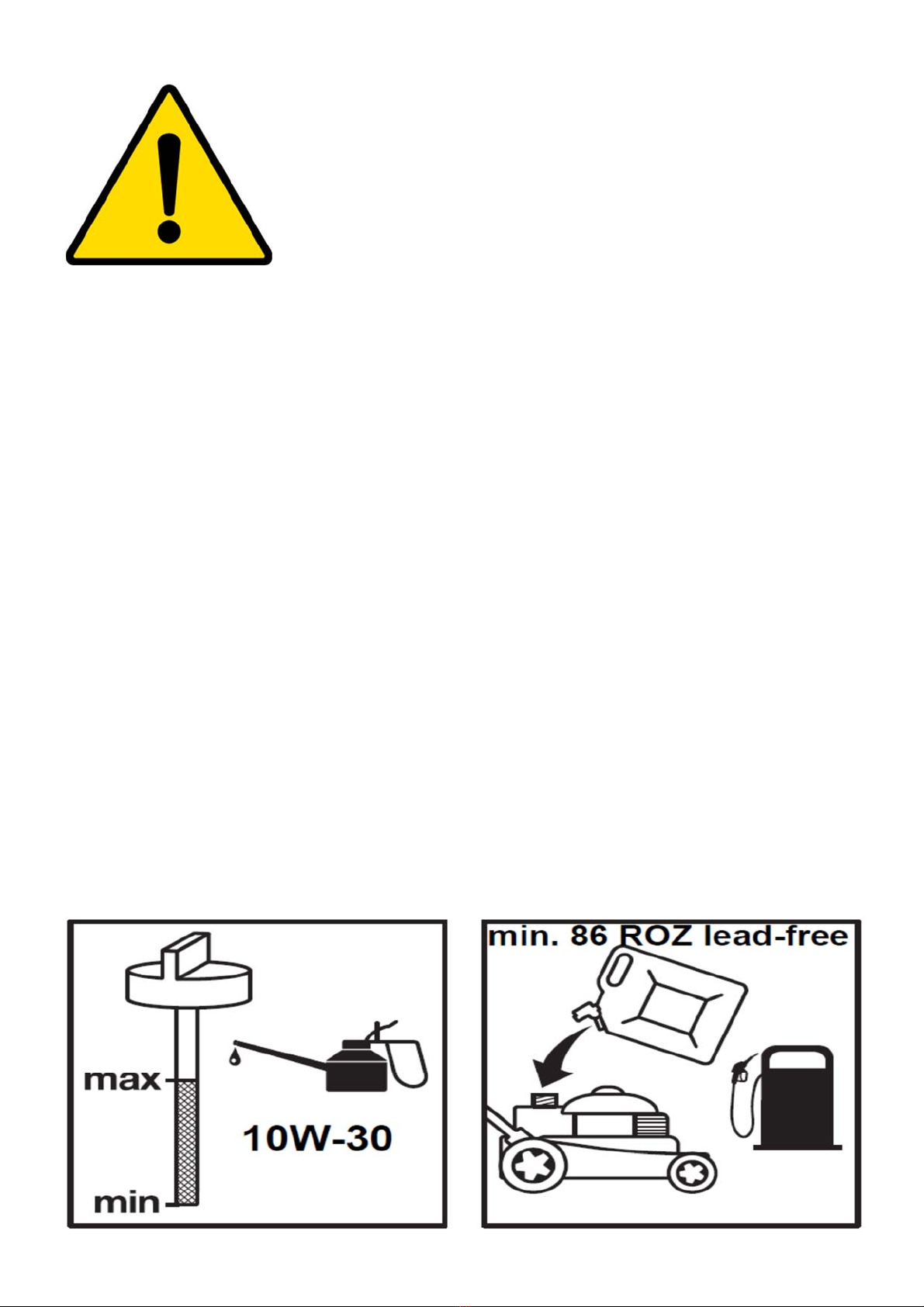
WARNING: Refuel in a well ventilated area with the engine stopped.

7
18
18
F
igure 4: GBD-46R (DYM1676CE-3)
Figure 3: GBD-46REV (DYM1676SED-3)
GBD-51RE
V
(
DYM1678SD-3
)
3. PARTS DESCRIPTION
1.
upper handle
2.
self-drive control
handle
3.
starter handle
4.
quick release
skewer
5.
grass catcher
6.
height
adjustment
lever
7.
wheel
8.
oil filler pipe & dipstick
9.
deck
10.
spark plug
11.
fuel tank cap
12.
cable clamp
13.
choke lever
14.
brake control handle
15.
air filter
16.
carburetor
17.
muffler
18.
water hose
connector
19.
side discharge
wedge
20.
side discharge
flap
21.
speed
adjustment
22.
mulching wedge
23.
front wheel locking handle
24.
front wheel bracket
25.
front wheel
26.
height adjustment knob
13
3
1
2
13
5
6
7
20
19
10
8
12
21
14
11
4
14
15
15
16 16
17
17
10
19 20
8 9
F
igure 7: valid for all models
F
igure 8: GBD-51R (DYM162601)
22
23
24
26
25
14
1
13
4
5
7
20
19 17
11
12
15
10
2
3
8

8
4. TECHNICAL DATA
model GBD-46R
(DYM1676CE-3) GBD-51R
(DYM162601) GBD-46REV
(DYM1676SED-3) GBD-51REV
(DYM1678SD-3)
engine type DG600 DG600 DG600E
(DYM1P70FE)
DG600E
(DYM1P70FE)
engine build 4-stroke, overhead valve, single cylinder
engine displacement (bore &
stroke)
173 cm3 (70 * 45 mm)
nominal power 3.6 kW
blade length 460 mm 510 mm 460 mm 510 mm
max. torque 9.5 Nm at 2700 min-1
cooling system forced air
lubrication systems forced splash
starting method recoil starter electric & recoil starter
electric starter battery ▬12 V, 4.5 Ah • type FM1545
charger for electric starter battery ▬Input: 100 – 240 V AC, 50 – 60
Hz, 0.32 A
Output: 13.8 V DC, 0.5 A
Type: HYCH0131380500G
ignition system TCI
PTO shaft rotation counter-clockwise
spark plug gap 0.7 - 0.8 mm
rated speed 2800 min-1
valve clearance (cold) 0.1 - 0.15 mm
fuel tank capacity 1.8 l
motor oil quantity needed 0.4 l
grass catcher capacity 60 l
net weight 36.0 kg 39.2 kg 38.0 kg 42.3 kg
height adjustment 25 - 75mm, 7
positions
25 – 75 mm, 6
positions
25 - 75mm, 7
positions
25 – 75 mm, 7
positions
guaranteed sound pressure level
at the operator’s position
(according to EN ISO 5395-1
annex F & EN ISO 5395-2, EN ISO
4871
83.7 dB(A)
K = 3 dB(A)
83 dB(A)
K = 3 dB(A)
83.7 dB(A)
K = 3 dB(A)
81.9 dB(A)
K = 3 dB(A)
measured sound power level 93.9 dB(A)
K = 1.81 dB(A)
96.4 dB(A)
K = 1.80 dB(A)
93.9 dB(A)
K = 1.81 dB(A)
95.0 dB(A)
K = 2.88 dB(A)
guaranteed sound power level
(according to 2000/14/EC)
96 dB(A) 96 dB(A) 96 dB(A) 98 dB(A)
vibration (according to EN ISO
5395-1 annex G & EN ISO 5395-
2)
5.37 m/s²
K = 1.5 m/s²
11.40 m/s²
K = 1.5 m/s²
5.37 m/s²
K = 1.5 m/s²
3.37 m/s²
K = 1.5 m/s²

9
5. ASSEMBLY
5.1 FOLDABLE HANDLE
1. Fix the lower handlebars into the unit body with bolts, washers and locking knobs (fig. 9 & 10).
2. Open the two quick release skewers to unfold the upper handlebar (fig. 11).
3. Bring the the upper handlebar in the operating position. Close the two quick release skewers (fig. 9 & 10).
4. Adjust the tension by turning the lock nut with a wrench (fig. 12).
5. Attach the cable clamp at the shown position with the bowden cables underneath (fig. 13).
Figure9 Figure10 Figure11
Figure 12 Figure 13
5.2 ADJUST HANDLE TO BODY HEIGHT
1. Open the two quick release skewers to unfold the upper handlebar .
2. Rotate the upper handle centered in the angle adjusting to an ergonomic height.
3. Push the locking lever closed to connect the lower handle and the upper handle.
Figure 14
5.3 MOUNTING AND DISMOUNTING THE GRASS CATCHER
1. To fit: Raise the rear cover and hitch the grass catcher to the rear of mower (fig.13-18).
2. To remove: Lift the rear cover. Lift up the grass catcher.
Do not start the
engine before you
fill oil in!
bolt
washer locking knob
locking lever
locking lever
cable clamp

10
Figure 15 Figure 16 Figure 17
5.4 STARTER HANDLE
Gently pull out the starter handle from the engine to the rope guide (fig. 18 & 19).
Figure 18 Figure 19
5.5 HEIGHT OF CUT
5.5.1 for all models
Apply outward pressure to disengage the lever from the right rear wheel rack. Move the lever forward or
backwards to adjust the cutting height. The setting applies to all 4 wheels with one lever (fig. 20).
Figure 20
5.5.2 for GBD-51R (DYM162601)
For this model, the central height adjustment only applies to the rear wheels. The front wheel is also
equipped with a height adjusting system (25 mm to 75 mm). Lift the mower up on front. Unscrew the height
adjustment knob #26. Insert the axle into the appropriate hole in the bracket for your desired height. Tighten
the knob.
rope guide
starter handle

11
Figure 21
Set the front wheel to the same height as the back wheels!
5.6 HANDLE PANEL
5.6.1 for GBD-46R (DYM1676CE-3)
This model is equipped with a storage box. Push the button in the center to open and lock it (fig. 22).
Figure 22
5.6.2 for GBD-46REV (DYM1676SED-3) & GBD-51REV (DYM1678SD-3)
This model is equipped with a starter battery located in the center of the dashboard. It has got a cup & bottle
holder, too.
Figure 23
Please always put a lid on the drinks in the cupholder.
Holes for different mowing
heights. The height in mm
is embossed in the
bracket.

12
6. “3 IN 1”
Your lawn mower is equipped with accessories to be retrofitted based on the application purpose:
1. normal function rear discharge into grass catching bag #5
2. mulching mower mulching plug #22
3. side-discharge side discharge wedge #19
What is mulching?
When mulching, the grass is simultaneously cut and finely chopped and returned to the grass strip as natural
fertilizer.
Hints for mulch-mowing
- Cut-back by max. 2 cm (e.g. from 6 cm to 4 cm grass height).
- Use a sharp cutting knife.
- Do not mow wet grass.
- Regularly clean mulching wedge, housing inner side and mowing blade.
6.1 mulching mower
WARNING: Operate only with a stopped motor.
1. Lift the rear cover and remove the grass catcher #5.
2. Push the mulching wedge #22 into the deck. Lock the mulching wedge with the button into the opening on
the deck (fig. 24, 25).
3. Lower the rear cover again (fig. 26).
Figure 24 Figure 25 Figure 26
6.2 side discharge mowing
WARNING: Operate only with a stopped motor.
1. Lift the rear cover and remove the grass catcher #5 (see 6.1).
2. Install the mulching wedge #22.
3. Unlock the lid #20 (fig. 27).
4. Lift the lid #20 (fig. 28).
5. Mount the side discharge channel #19 on the support pin of the sideward flap (fig. 29).
6. Lower the flap - the flap lies on the side discharge channel (fig. 30)
locking button

13
Figure 27 Figure 28 Figure 29
Figure 30
6.3 rear discharge into grass catcher
WARNING: Operate only with a stopped motor.
To return back to normal mowing, remove the mulching wedge and the side discharge accessory and store
them for later usage.
7. OPERATING INSTRUCTIONS
7.1 BEFORE STARTING
7.1.1 Adding oil
Be sure to put oil in the engine before starting. Use a clean and high-quality oil SAE30 and API.SG, SH or SJ
classification.
Use 4-stroke motor oil that meets or exceeds the requirements
for API service classification SH, SJ, or equivalent. Always
check the API service label on the oil container to be sure it
includes the letters SH, SJ, or equivalent.
SAE 10W-30 is recommended for general use. Other
viscosities shown in the chart may be used when the average
temperature in your area is within the indicated range.
Engine oil capacity: 0.6 l
7.1.2 Oil level check
CAUTION: This engine is delivered without oil. Starting
the engine without oil will destroy it.
locking mechanism

14
1. Check oil level when engine is stopped.
2. Remove the oil filler cap/ dipstick and wipe it clean.
3. Insert the oil filler cap/ dipstick into the oil filler neck
without screwing it in; remove it to check the oil level.
4. If the oil level is near or below the lower limit mark on the
dipstick, refill with the recommended oil to the upper limit
mark (bottom edge of the oil fill hole). Do not overfill.
5. Reinstall the oil filler cap/ dipstick.
7.1.3 Adding fuel
DANGER! Petrol is highly flammable.
Use unleaded gasoline with a pump octane rating of 86 or higher. This engine is certified to operate on unleaded
gasoline. Unleaded gasoline produces fewer engine and spark plug deposits and extends exhaust system life.
Never use an oil/ gasoline mixture.
●Stop engine and keep heat, sparks, and open fire away.
●Refuel only outdoors.
●Wipe up spills immediately.
Fuel can damage paint and some types of plastic. Be careful not to spill fuel when filling your fuel tank. Damage
caused by spilled fuel is not covered under warranty. Never use stale or contaminated gasoline. Avoid getting
dirt or water in the fuel tank.
1. Remove the fuel cap.
2. Add fuel to the bottom of the fuel level limit in the neck of the fuel tank.
3. Do not overfill. Wipe up spilled fuel before starting the engine.
4. Install and tighten the fuel cap.
5. Fuel tank capacity: 1.8 l
7.2 START ENGINE AND ENGAGE BLADE
7.2.1 for GBD-46R (DYM1676CE-3) & GBD-51R (DYM162601)
1. The unit is equipped with a rubber tip #10 on the spark plug, make sure it is fastened securely.
2. Open the fuel valve (fig. 31). Set it to the “ “ position.
3. For a cold start, turn the choke lever #13 to “ ” position. Immediately after the engine starts
turning, turn the choke lever to the “ ” position (fig. 32/ 33).
4. Standing behind the unit, push & hold the brake control handle against the upper handle (fig. 34).
5. Pull out the starter handle slowly until you feel a resistance in the rope. Then completely pull the rope out
with one fast movement. Once the engine starts, return it slowly to the rope guide bolt (fig. 35).
Release the brake control handle to stop engine and blade.
6. After having finsihed to mow, please turn the fuel lock to the ” ”.position (fig. 36).

15
Figure 31 Figure 32. GBD-46R (DYM1676CE-3) Figure 33: GBD-51R (DYM162601)
Figure 34: GBD-46R (DYM1676CE-3) Figure 35: GBD-51R (DYM162601) Figure 36
7.2.1 for GBD-46REV (DYM1676SED-3) GBD-51REV (DYM1678SD-3)
7.2.1.1 starting manually
1. The unit is equipped with a rubber tip #10 on the spark plug, make sure it is fastened securely.
2. Open the fuel valve (fig. 31). Set it to the “ “ position.
3. For a cold start, turn the choke lever #13 to “ ” position. Immediately after the engine starts
turning, turn the choke lever to the “ ” position (fig. 37).
4. Standing behind the unit, push & hold the brake control handle against the upper handle (fig. 34).
5. Pull out the starter handle slowly until you feel a resistance in the rope. Then completely pull the rope out
with one fast movement. Once the engine starts, return it slowly to the rope guide bolt (fig. 38).
Release the brake control handle to stop engine and blade.
6 After having finsihed to mow, please turn the fuel lock to the ” ”.position (fig. 36).
Figure 38
7.2.1.2 starting electrically
1. The unit is equipped with a rubber tip #10 on the spark plug, make sure it is fastened securely.
2. Open the fuel valve (fig. 39). Set it to the “ “ position.
3. For a cold start, turn the choke lever #13 to “ ” position. Immediately after the engine starts
turning, turn the choke lever to the “ ” position (fig. 40).
F
igure 37

16
4. Standing behind the unit, push & hold the brake control handle against the upper handle (fig. 41).
5. Press the starter button on the panel (fig. 42). Release it once the motor starts runnning. Turn the chocke
lever to
Release the brake control handle to stop engine and blade.
6. After having finsihed to mow, please turn the fuel lock to the ” “ position (fig. 43).
Figure39 Figure40 Figure41
Figure 42 Figure 43
7.3 OPERATION PROCEDURE
During operation, tightly hold the brake handle with both hands.
Note: During operation, when the brake handle is released, the engine and thus the lawnmower stops to
operate.
7.3.1 front wheel fixation on GBD-51R (DYM162601)
Switch the locking handle #23 to “ “position to allow the steering of the front wheel #25 (fig.44).
Switch the locking handle to” ’position to fix the wheel in a straight position (fig. 45).
Figure 44 Figure 45
WARNING: In order to avoid any unintentional start-ups of the lawn mower, it comes equipped with an
engine brake which must be pulled back before the engine can be started. To mow, hold the lever in the
working position. When the engine control lever is released, it must return to its initial position, at which point
the engine automatically switches off and the blade stops immediately. Before you start to mow, check the
starter button

17
start/stop lever several times to be sure that it is working properly. Ensure that the tension cable can be
smoothly operated (i.e. is not catching or kinking in any way).
7.4 STOPPING THE ENGINE
Release the brake control handle to stop the engine and blade (figure 46).
Figure 46
7.5 REAR-WHEEL DRIVE
for GBD-46R (DYM1676CE-3) & GBD-51R (DYM162601)
Grip the self-drive control handle, the lawnmower will move forward automatically with about 3.0 km/h.
Release the self-drive handle, the lawnmower will stop moving (fig. 47).
Figure 47
for GBD-46REV (DYM1676SED-3) & GBD-51REV (DYM1678SD-3)
The mower is equipped with a speed adjusting system which can adjust 4 speeds from 3.0 km/h to 4.5 km/h.
Position 1: Slowest position. Position 4: Fastest position (fig. 49).
Operation steps:
1. Release the self-drive control handle #2.
2. Adjust the desired speed with handle #21.
3. Pull rasp the self-drive control handle #2. (fig. 49).

18
Figure 48 Figure 49
CAUTION: your mower is designed to cut normal residential grass up to 250 mm height.
Do not attempt to mow through unusually tall dry or wet grass or piles of dry leaves. Debris may
accumulate on the mower deck or contact the engine exhaust presenting a potential fire hazard.
7.6 OBTAINING THE BEST MOWING RESULTS
Clear the lawn from stones, branches, wire or other foreign objects. The mower could whirl these up and
throw to any direction. leading to serious personal injury as well as to damage to property, surrounding
objects and the mower itself. Do not cut wet grass. Wet grass clippings tend to clog the discharge opening the
underside of the deck. Cut no more than 1/3 of the length of the grass. When mowing long grass you may
have to cut the lawn in two stages, lowering the blade another 1/3 of the length for the second cut. Mow in a
different pattern than you did the first time. To overlap the cutting tracks on each pass will also help to clean
up any stray clippings. The mower must be operated at full throttle to get the best cut. Clean the underside of
the deck after each use to remove grass lumps that prevent proper mulching. When mowing leaves, make
sure they are dry and are not collected to large piles. (Do not wait for all the leaves to fall off the trees before
you mow.)
WARNING: If you strike a foreign object, stop the engine. Remove the spark plug, thoroughly inspect the
mower for any damage and repair the damage before restarting and operating the mower. Extensive vibration
of the mower during operation is an indication of damage. The unit should be promptly inspected and
repaired.
7.7 GRASS CATCHER
There is a level indicator on the top of the grass catcher that shows whether the catcher is empty or full.
- The level indicator moves if the catcher is not full and the mower is tuned on (fig. 51).
- Once that indicator stops moving, the grass catcher is full. Turn the mower off. Empty and clean the
grass catcher.
Figure 50 Figure 51
level indicator

19
7.8 DECK
The underside of the mower deck should be cleaned after each use to remove any grass clippings, leaves
and dirt. These residues contain active organic substances that favor rust and corrosion. The deck may be
cleaned by tilting the mower and scraping clean with a suitable tool (make certain the spark plug is
disconnected).
Always lay the mower on that side where the air filter is directed upwards. The air filter lying face
down will lead to fuel and oil spills.
7.9 HEIGHT ADJUSTMENT INSTRUCTIONS
For GBD-46R (DYM1676CE-3), GBD-51REV (DYM1678SD-3),GBD-46REV (DYM1676SED-3)
Your mower is equipped with a central height adjustment lever offering 7 height positions.
Height means distance of blade to ground. It can be adjusted from 25 mm to 75 mm (7 height positions)
(fig. 52) .
1. Stop the mower before changing the cutting height.
2. The central height adjustment lever offers you 7 different height positions.
To change the height of cut, squeeze the adjustment lever towards the wheel and move it left or right
along the scale to your to selected height.
Figure 52
For GBD-51R (DYM162601)
Your mower is equipped with a height adjustment lever offering 7 height positions for the rear wheels.
Height means distance of blade to ground. It can be adjusted from 25 mm to 75 mm (7 height positions)
(fig. 53) .
1. Stop the mower before changing the cutting height.
2. The central height adjustment lever offers you 7 different height positions.
To change the height of cut, squeeze the adjustment lever towards the wheel and move it left or right
along the scale to your to selected height.
Figure 53
The front wheel needs to be adjusted separately.
1) Lift the mower up on the front wheel bracket #24. Pull out the support lever counterclockwise (fig. 54 &
55)).
1 - lowest
7 - highest
75 mm
25 mm

20
2) Fix the support lever into the holder body, make sure the support lever is located in position (fig. 55 & 56).
3) To change the height of rear wheel, unscrew the height adjustment knob #26. Pull out the wheel axle
sideward and insert it into another hole relating to the desired height. The height in millimeters is
embossed in the bracket #26. Reassemble (fig. 57 & 58).
Figure 54 Figure 55 Figure 56
Figure57 Figure58
Remember the cutting height on the front wheel should be the same as on the rear wheels!
8. MAINTENANCE INSTRUCTIONS
Good maintenance is essential for safe, economical and trouble-free operation. It is also necessary to maintain
the low emission level of the engine.
Remember that an authorized servicing dealer knows your engine best and is fully equipped to maintain and
repair it.
SPARK PLUG
Use only original manufacturer replacement spark plugs. For best results, replace the spark plug every 100
hours of use.
Recommended spark plug ►Torch F7RTC.
WARNING:
Incorrect spark plugs can cause engine damage.
For good performance, the spark plug must be properly gapped and free of deposits.
1. Disconnect the cap (part 10) from the spark plug, and remove any dirt from the spark plug area.
2. Use the spark plug wrench (accessory part A) to remove the spark plug.
3. Inspect the spark plug. Replace it damaged or corroded, if the sealing washer is in poor condition or if the
electrode is worn.
This manual suits for next models
7
Other Gardol Lawn Mower manuals

Gardol
Gardol 195107HRB User manual

Gardol
Gardol GVL-M-1800-37 User manual

Gardol
Gardol GTG 84 RB User manual

Gardol
Gardol GEM-E33 User manual

Gardol
Gardol 34.131.10 User manual

Gardol
Gardol GAM-E 33/1Li User manual

Gardol
Gardol GAM-E36Li User manual

Gardol
Gardol 155107HRB User manual

Gardol
Gardol GAM-E43Li User manual

Gardol
Gardol GBH 46 R User manual

Gardol
Gardol GE 37 User manual

Gardol
Gardol GEM-E 1536 User manual

Gardol
Gardol GEM-E36 User manual

Gardol
Gardol GTR-E 51 R HW User manual

Gardol
Gardol GEM-E43 User manual

Gardol
Gardol ESE 4216 User manual

Gardol
Gardol GBW 53 RE User manual

Gardol
Gardol GEM-E 1742 User manual

Gardol
Gardol GBWO 46 User manual

Gardol
Gardol G125-85F User manual