Garford Robocrop User manual

Manual
Version 6.4 (Draft)
Disclaimer
Considerable effort has gone into making Robocrop reliable under
normal commercial conditions. However, it is possible that under some
adverse circumstances the guidance system will be unable to operate
reliably. It is the operator’s responsibility at all times to ensure that the
machine is operating in a satisfactory manner. Should excessive crop
damage occur operation should cease and if necessary, your Garford
dealer should be contacted for advice.

2
Contents
1. Preface.......................................................................................... 3
2. Safety............................................................................................ 4
3. Assembly....................................................................................... 5
Step 1 –Mounting the console.................................................... 5
Step 2 –Setting up the linkage arms........................................... 5
Step 3 –Reducing lateral movement...........................................5
Step 4 –Levelling the implement.................................................5
Step 5 –Connecting the hydraulic hoses.....................................5
Step 6 –Connecting implement loom to the console...................5
Step 7 –Connecting the power supply........................................ 5
Step 8 –Starting the tractor and console.....................................6
Step 9 –Checking hydraulic operation........................................ 6
4. Start up and working screen……………......................................... 7
5. Getting to work in the field.............................................................. 9
Step 1 –Selecting configuration file and crop size…………....... 9
Step 2 –Checking camera height and inclination in the field...... 9
Step 3 –Initial running and adjusting camera lateral position….. 11
6. Notes on operation with a correctly set up machine………………..12
7. Information screens and menus……………………………………… 13
Setup menu…………………………………………………………. 14
Advanced set up & diagnostics menu………………………........ 15
Configuration file editor……………………………………………. 17
8. Maintenance and storage.............................................................. 24
9. Service menu…………………………………………………………… 24
10. Troubleshooting............................................................................. 25
LED Blink codes………………………………………………….. 25
Console fault codes………………………………………………… 26
Flow Charts…………………………………………………………... 27
Copyright notice
The computer vision guidance and control software and the associated
configuration tool on all Robocrop systems are copyright Tillett and Hague
Technology Ltd.
This product also makes use of public domain operating system code. Under
the terms of the GNU general public licence and/or the University of
California, Berkeley (UCB) license copies of the public domain software are
available on request.

3
1. Preface
Congratulations on purchasing a Robocrop precision guided implement.
Robocrop precision guided implements are guided by a computer controlled steering system.
There are 3 main components to the system.
1. A digital camera or cameras mounted on the implement looking ahead at a wide area of
crop normally taking in several rows.
2. A cab mounted console containing a computer to analyses camera images and find exact
row centres.
3. A hydraulic side shift (or steered discs) controlled by the computer to keep the camera
centrally over crop rows and the implement precisely on track.
Schematic of Robocrop on a rear mounted inter-row cultivator with side shift
Robocrop uses a colour camera to pick out green crop and weed from backgrounds containing
soil, stones and trash. (Consult your Garford dealer for systems to work in red crops.) Robocrop
locates crop rows within a scene by matching a template corresponding to the known planting
pattern with crop rows as they appear in the camera image. That image is displayed live on the
console with the template overlaid as green lines.
Matching a template to a broad area of crop rather than locating individual rows improves reliability
especially when parts of those rows are not present or obscured by weeds. Template shape is
determined by a configuration file pre-programmed to suit a particular crop planting geometry and
implement configuration. Different configuration files can be created for different crops and
implements.
A good match between the template and crop rows is very important for accurate row following.
Console working screen showing a typical live video image with the template superimposed as
green lines over crop rows.
Camera
Micro
controller
and valves
for hydraulic
side shift
Console

4
2. Safety
1. When carrying out repairs or adjustments to a side shift, steering discs or
implement, ensure that the Robocrop system is switched off and also that the
hydraulic supply is off.
Be aware that spurious speed signals can be generated potentially causing
the side shift/steering discs to move unexpectedly. This is most likely if
odometry is generated via GPS, which is inclined to drift, or via computer
vision, particularly if people are moving in the camera field of view.
2. Never conduct maintenance work on the side shift mechanism while it is
supporting the implement.
3. The side shift and steered disc mechanisms forms pinch, trap and shear
points. Be aware of these when carrying out maintenance.
4. Regularly check the condition of hydraulic hoses and fittings.
5. Do not allow other persons to ride on or work near the implement when it is in
operation.
6. The power supply cable has a 20Amp fuse fitted near to the battery terminals.
This is for short circuit protection and must not be omitted.
7. When routing the loom and power supply cables ensure that they do not
cause a restriction or trip point in the cab.

5
3. Assembly
The following steps outline how the Robocrop precision guided implement should be set up.
Step 1 - Mounting the console
Mount the console in the tractor cab in a position where it can be clearly seen, but does not
obscure operator's visibility. Four M6 tapped holes at a square 100mm pitch in the rear of the
console facilitate mounting to a bracket. A number of alternative mounting arrangements are
possible, but it is recommended that the chosen method should provide some vibration isolation.
Caution
•The console should be protected from severe vibration.
•Do not use longer screws than those supplied otherwise damage to the console may result!
Step 2 –Hitching to the tractor
Position the tractor and implement on a level surface. Check that the tractor’s lower link arms are
evenly adjusted and hitch the tractor to the 3-point linkage points on the side shift frame.
Caution
•The side shift 3-point linkage points are to standard category 2 dimensions and so must be
attached to a similar tractor linkage.
•Once the 3-point linkage is correctly fitted stop the tractor and apply the handbrake.
Step 3 –Reducing lateral movement
Adjust the stabiliser links to prevent lateral movement of the lower link arms.
Caution
•For side shifting front mounted systems it is particularly important that there is no lateral
movement in the linkage.
Step 4 –Levelling the implement
With the cultivator on the ground, adjust the top link so that the cultivator is level, front to rear
(camera pole(s) should be vertical).
The control system loom and hydraulic hoses can now be routed from the implement to the tractor.
Caution
•Clipping the loom and hoses to the top link should keep them clear of catch points.
•Make sure that the linkage can be operated over its full range without stretching or chaffing
the loom conduit or hoses.
Step 5 –Connecting the hydraulic hoses
Plug the hoses into a suitable double acting valve connection on the tractor. Markers on the hoses
indicate the following:
Supply –RED Return - BLUE.
Step 6 –Connecting the implement to the console
The cable/conduit from the implement module should be routed into the tractor cab and through to
the console.
Caution
•Do not to allow the loom to restrict access to or exit from the cab or act as a trip point.
Plug the multi pin plug into the socket in the bottom of the console.
Caution
•Note the correct alignment of the tabs in the plug and socket and avoid excessive force in
pushing the connector together. If you have any problems with this connector consult
your dealer as incorrect assembly may seriously damage the computer.

6
Step 7 –Connecting the power supply
The 12V power supply cable running from the implement module should be connected directly to
the tractor battery or via purpose designed power sockets. Cigarette lighter sockets are not
suitable.
Caution
•Route the cable carefully ensuring that it cannot become trapped or chaffed.
•The 20amp fuse at the battery terminal end of the cable is for short circuit protection and
must not be removed.
•The polarity is denoted by + and –marker rings on the cables. The fuse is on the + cable.
Step 8 –Start the tractor and console
With the implement still on the ground check that the spool valve is in neutral and all persons are
well clear. Start the tractor then press the console power button which will remain illuminated. Wait
for the system to "boot up" with a few text screens then a graphics start up screen with touch
screen buttons should appear. Press the touch screen button labelled Inter-Row. A new screen
with a live video image will appear, this is referred to as the working screen.
Step 9 –Checking hydraulic operation
Set the tractors hydraulic control to provide a constant flow to the implement with the facility to
disengage the supply immediately should a fault occur.
Once the system has booted up and the working screen is displayed, lift the implement clear of the
ground and engage the hydraulic supply. The side shift or steered discs should centralise.
If the side shift or discs were already central and you wish to test them press the second touch
screen button from the bottom on the right labelled “manual”. The hydraulic side shift/steering is
now in manual mode and can be operated via the touch screen buttons labelled with left and right
arrows. Each button press steps side shift/steering by 7% of its stroke. Repeated pressing (but
not holding your finger down) will result in continuous travel up to the end of the stroke. This
procedure can be used to check that hydraulic flow is in the correct direction and that the side shift
rate is correct. A normal side shift rate would be 0.1m/s (e.g. 3s to travel a 0.3m stroke). To return
to normal automatic mode press the same button again. The side shift/disc will stay in the position
until the implement is lowered and raised again, or the machine starts to travel forward.
Caution
•Side shift/disc travel all the way to one side on lifting the implement may indicate that the
hydraulic supply is connected the wrong way.
•Rapid side shift/disc oscillations back and forth about the central position indicate that the
hydraulic flow rate is too high. The tractor flow control should be turned down. Alternatively,
the hydraulic flow control valve on the implement may be adjusted, see picture.
•Only adjust the flow control valve with the implement on the ground and the tractor engine
switched off.
The machine is now ready for work, though before proceeding to the operational phase it is worth
familiarising yourself with the working screen.

7
4. Start up and working screen
Turn the system on by pressing the console button for about a second until the button is
illuminated. After some PC start up text the user is presented with a start-up screen offering the
choice between starting the guidance system, going directly to the set up screen, opening the
service menu or shutting down.
To get to the working screen press touch screen button with the crop row symbol. When a press
has been detected the touch screen button will become darker, though the function is only
activated when your finger is released.
The working screen as illustrated below has the following features:
•A live camera video image over which are superimposed two sets of markings. The first are
green lines representing the template to which crop rows are matched. The second are a
series of eight crosses arranged from the top to the bottom of the image. These represent how
well the template lines up at different levels up the image. Blue crosses indicate a good
match. Yellow and red crosses indicate a poor match.
•Systems with multiple cameras display live thumbnail videos along the top of the display.
•An image quality gauge to the left of the screen giving relative indication of likely
tracking performance. The higher the green bar the better. A low bar indicates
either a poor template match or poorly defined crop rows. Guidance will, under
most circumstances, operate down to an indication of approximately 20% albeit at
reduced accuracy.
•Information symbols at the bottom left of the display:
oA warning triangle indicating poor tracking is displayed if estimated
error in lateral position exceeds 25mm. The number between the
arrows is the section to which the warning applies. On seeing this
warning users should check performance on the ground. If enabled
the warning triangle will be accompanied by an audible warning.
oAn implement lift symbol is displayed if the lift sensor detects the
implement is lifted.
oA circular red braked symbol is displayed if the implement is down but
not moving.
•A speed gauge on the right shows forward speed which should match tractor
speed. The speed bar is green up to 11kph and red over 15kph, which is
normally a sensible operating limit, though guidance is good to 20kph where
soil/crop conditions permit.

8
•A green dot and red/green chevrons below the image indicate side shift
position. A red chevron with a vertical bar indicates the limit of travel has been reached.
This should not be allowed to occur for extended periods.
•The fine offset gauge shows the amount of left or right bias set by the user. This is used to
compensate for minor lateral camera misalignment, but can also be useful on side slopes.
By default, fine offset has six 1cm steps in either direction, though the number and size of
steps is configurable.
The function of touch screen buttons located along the right of the screen are given below:
•Spanner symbol, this button accesses the setup menu (section 9).
•“Select” on multi camera systems and blank for single camera systems. This touch screen
button toggles between cameras affecting the main image displayed and fine offset context.
Alternatively, pressing on a thumbnail image will also select it for full size display.
•←moves fine offset left 1cm, or when in manual mode, side shifts/steers 7% left.
•→moves fine offset right 1cm, or when in manual mode, side shifts/steers 7% right
•Touch screen button labelled “Manual” disables vision steering and allows the user to move
left or right manually in steps of 7% of potentiometer stroke for each press of the arrow
buttons. For disk steered machines this is achieved by automatically steering the discs to
maintain the desired slide position. To prevent mechanical damage these functions only
operate when lifted or moving.
In manual mode green lines representing the template and purple cross hairs are locked on
the screen whilst retaining a live video image. These are useful when adjusting cameras.
Return to vision guidance by pressing same button, now labelled “Camera”, again. By
default the side shift/discs remain in the position they were placed manually until forward
movement under vision guidance is commenced, or an implement lift is detected. The later
will centralise the side shift/discs. Alternatively, systems can be configured such that side
shift/discs centralise on entry into manual mode (section 9.3).
For single section side shift machines manual control is retained with a normal tracking
screen when moving forward so operators can see if vision guidance is likely to succeed.
For machines with mechanical guidance feelers the “Manual” button cycles between
manual mode, feeler and vision guidance. In manual or feeler guidance mode the fine
offset slide bar is replaced by Text in red capitals indicating the mode in use. For machines
fitted with a remote override manual control box the text would say “REMOTE MANUAL”
when the box was switched on.
•Pressing the touch screen button with the power switch logo enters a shutdown screen from
which you can confirm shutdown.
9
5. Getting to work in the field
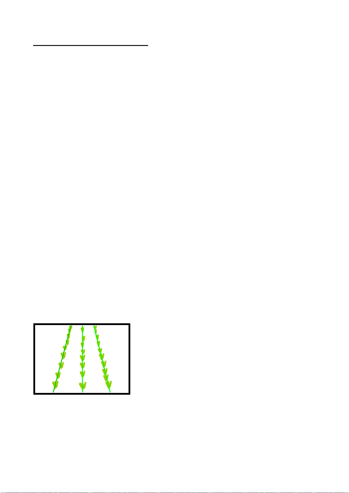
The most important procedure to ensure good guidance is to match the template, as illustrated by
the green lines, to crop rows as they appear in the live video image. The following steps outline
how to get the best match and hence achieve good guidance.
Tip
For the first few hundred meters of running after commissioning Robocrop learns a term known as
camera skew (see section 7.3) Camera skew compensates for minor errors in camera orientation
in the horizontal plane. Wherever possible we recommend that set up runs (step 4) are conducted
in crop showing the clearest rows available so that camera skew is learned as quickly and
accurately as possible. High visibility rows also help manual alignment checks (step 3). We also
recommend that side slopes and intense partial shadows are avoided during initial running. Once
set up is complete more challenging situations can be tackled. It is also possible to view the
current value of camera skew and reset it manually (see section 7.3).
Step 1 –Selecting configuration file and crop size
From the working screen press button labelled with a spanner symbol to reach the setup screen.
The top line of this screen indicates crop size (height) settings under categories of small (<5cm)
medium (5-15cm) and large (>15cm). The second line lists the available configuration files. Use
the buttons labelled with arrows to ensure that the highlighted options correspond to the crop and
crop size being used for setup and initial running.
Check details at the bottom of the screen to ensure selected configuration file settings match crop
and camera geometry.
If either crop geometry or configuration settings are not correct refer to section 7 for instructions on
making the necessary changes.
To return to the working screen by pressing the button labelled “OK”.
Step 2 –Checking camera height and inclination angle in the field
Draw into the crop and set the cultivator down onto a typical section of crop row. The cultivator
should be level and set onto the rows as accurately, and as straight as possible with the camera at
its normal operating height (displayed in the “set up” screen).
Press button labelled “Manual”, The overlaid green lines representing the template should lock in
the centre of the screen.
Green lines superimposed over the live image should align with crop rows as illustrated below.
Tip
If crop rows are difficult to see in the live video image you can enhance them by placing high
visibility objects such as a strip of wood exactly over the row centre line.
Caution
If the overlaid green lines are not symmetrical on the screen (by more than 4 degrees) the camera
skew value may need resetting. Refer to the advanced set up & diagnostics menu in section 7.3.
✓

10
However, if the green lines appear narrower or wider than the real crop rows check the “crop
size”selected in the “set up”screen and change if appropriate. If this does not resolve the
problem, it may be that the camera height (measured from centre of lens to ground level) does not
match the figure displayed in the “set up” screen. The best solution is to measure the correct
position and move the camera accordingly. A less accurate, but sometimes satisfactory
alternative, is to adjust camera height until the “picture” looks correct as illustrated below.
If the camera is too low, then the template will appear narrower
than crop rows. In this case raise the camera.
If the camera is too high, then the template will appear wider
than crop rows. In this case lower the camera.
If the template matches mid screen, but not at the top or bottom, check that the implement is level.
If it is camera inclination angle may need adjusting. Again the best solution is to make careful
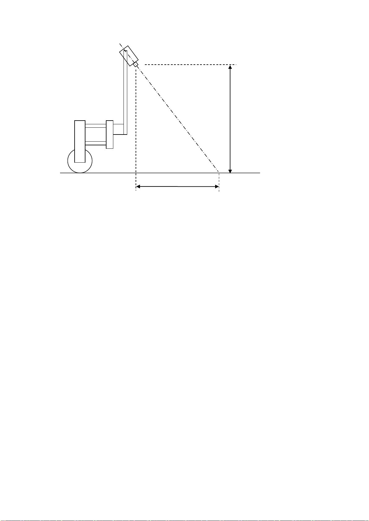
measurements and adjust accordingly. This may be done as follows. Go into the “set up” screen
and make a note of a distance called “look ahead”. Return to the working screen and press Sk5
labelled “manual”. Purple cross hairs will appear in the image. Now mark a point on the ground
directly below the camera lens (ideally using a plumb bob). From that point measure forward along
the ground and place an object at the “look ahead” distance. When viewed on the screen the
object should now coincide with the cross hairs intersection in the image centre. If it does not
camera inclination should be adjusted until it does.
Again a less accurate, but sometimes satisfactory alternative is to adjust camera inclination until
the “picture” looks correct as illustrated below.
If template lines appear narrower than crop rows at the top of
the image but wider at the bottom, then the camera is inclined
down too far. In this case rotate the camera up so it views
further ahead.
If template lines appear wider than crop rows at the top of the
image but narrower at the bottom, then the camera is
inclined up too far. In this case rotate the camera down so it
views less far ahead.
Good tracking will only be achieved if template lines are centred on all of the rows being tracked.
Note Remember to tighten any bolts loosened in the process of adjustment.
11
Step 3 –Initial running and adjusting camera lateral position
When you are happy you have a good template match press the button labelled “Manual” again to
return to the normal working screen ready for tracking. You can be sure that the machine is ready
for tracking if a line of blue crosses has appeared down the centre of the display.
Note
For initial set up runs almost all the crosses should be coloured blue and form a relatively straight
vertical line. If this is not the case, or a triangular tracking warning symbol is displayed, either the
machine is not correctly set up, or crop rows are not sufficiently well defined for initial running.
If tracking appears good set off slowly into the crop. The implement should quickly align with crop
rows. It is likely that after a short distance it will have settled at a small lateral offset. Small offsets
can be corrected using the fine offset facility available from the working screen. Buttons labelled
with left and right arrows adjust fine offset whose current position is displayed centrally below the
live video image. Each press of an arrow key biases the side shift in steps of 1cm (3/8”). Continue
down the field stopping occasionally to check lateral position. If the required fine offset exceeds
the available number of steps the camera should be physically moved as described below and step
3 repeated.
It is the operator's responsibility to decide at which point the vision guidance system
becomes 'lost'. If the system losses track of crop rows the operator should carefully guide
the implement through to the next good reference.
Garford accept no responsibility for damage to or loss of crop whatsoever.
After approximately 200m of running Robocrop should have learnt camera alignment (“camera
skew”) and lateral bias should therefore have stabilised. If fine offset is set to greater than two
steps, we recommend physically moving the camera along the toolframe by the equivalent
distance and resetting fine offset to zero.
Tip
If fine offset is set to the left, then the camera should be moved right as viewed from behind looking
forward.
Once you are confident that Robocrop is tracking accurately and reliably forward speed can be
increased. Working speeds up to 12 kph can be accommodated with Robocrop, however the
mechanical interaction of shares and shields on the soil and its effect upon plants will determine if
this is achievable.
“Camera
height”(m)
“Look ahead” distance (m)

12
6. Notes on daily operation with a correctly set up machine
•Before operation check that electrical and hydraulic connections are secure and that there are
no obstructions to side shift/disc movement.
•On first setting the implement down in the field check that the green overlaid lines representing
the template line up with crop rows and that overlaid blue crosses have appeared
approximately central in the image.
•Proceed with caution for first few meters checking that Robocrop’s speed gauge matches the
tractors and that implement alignment is good. If performance is satisfactory speed can be
increased. Robocrop’s tracking should be satisfactory up to 12kph, though soil movement
considerations may dictate a lower operating speed.
•Robocrop remembers fine offset settings from previous sessions and so there should not
normally be any need to adjust this unless changes have been made to camera position.
•Operating on side slopes will result in some lateral error due to the tractor “crabbing” across
the slope. Normally this is not significant, but in extreme cases it may be necessary to use the
fine offset function to compensate. If operating in this way remember to reverse the bias when
heading in the opposite direction and to return to a neutral setting when stopping work or
moving to a flat area. A similar technique can be used to compensate for crop bent laterally by
a cross wind.
•Each time the implement is lifted at row ends it will centralise ready for the next run.
•At the end of the day shut down by pressing the bottom right touch screen button labelled with
the power symbol and confirm with the “exit” button. This will shut down power to the entire
system though the console power button will briefly flash every 5 seconds to indicate that the
12V supply is connected. In this state the current draw is negligible.
If in doubt about any machine settings or operating procedures, please contact Garford Farm
Machinery on +44 (0)1778 342642.

13
7. Information screens and menus
Robocrop has a graphical working screen that conveys all the information necessary for normal
operation. A description of this screen is given in section 4.
A series of six touch screen buttons along the right of the display allow operators to access user
controls such as fine offset and manual control of side shift/steered discs. Their function is
described by labels superimposed on each button.
Set up procedures and more advanced information can be accessed via additional screens that
can be navigated to via the working screen. The function of the touch screen buttons changes with
each screen, but is always described by its label.
7.1 The Setup Menu
The setup screen can be reached by pressing the spanner button from the working screen. Three
settings “Crop size” and “Configuration” and “Crop Colour” (optional facility) can be altered in this
screen.
Navigation within the set up screen is achieved by moving the cursor over options using buttons
labelled with arrows. When the cursor is over an appropriate setting it can be selected by pressing
the button labelled “OK”.
“Crop size” increases template size to compensate for the crop canopy getting closer to
the camera as it grows. This avoids the need to physically adjust camera height when
moving between crops of different heights. Robocrop has settings for small, medium and
large crops. As a guide, crops up to approximately 5cm (2”) high are regarded as small,
5cm (2”) to 15cm (6”), medium and greater than 15cm (6”) high, large. On initial set up the
default will be medium, though Robocrop remembers crop size from the previous session
regardless of which configuration file was used.
“Configuration” allows users to select between alternative pre-programmed configuration
files for different crop planting geometries requiring different templates.
The main parameters of the chosen configuration file are displayed at the bottom of the
setup screen, they are:
Camera number
Viewing - Number of rows being used for tracking.
Spacing - The row spacing between the rows being viewed.
Camera height - Distance vertically from lens to ground when in work
Camera look ahead –Horizontal distance along the ground from a point vertically below
the lens to the centreline of sight (marked by cross hairs in “Manual” mode).
14
“Crop colour” (optional facility) –For green crops select “Green”. Selecting
“Red” inverts colour segmentation so that plants that are completely red are tracked.
Where crops have red outer leaves and a green centre, users should select “R & G”. It is
also possible to select “Custom” colour which can bias the colour used by the system to
search for foliage. This can be advantageous on crops such as brassicas or alliums with a
blue/green colour (a value of about 50 has often be found to be satisfactory).
For plants with particularly unusual colours that cannot be tracked using any of the normal
colour options an Infra-Red camera can be fitted. This will be automatically detected and
is recognisable by monochrome video images.
If a suitable configuration is not available, it can be created. We recommend customers
ask their Garford distributor for an appropriate configuration file. However, experienced
users can use the configuration file editor (section 7.4) to create their own.
7.2 Advanced set up & diagnostics menu
This screen is reached from the set up screen by pressing the top right button labelled with a
spanner ++ symbol. Navigation within this screen is similar to the set up screen.
The first three items on this screen are for information only and cannot be changed by the user.
Area worked is based on distance x width.
The remaining items on this screen are as follows:
Current job
Provides resettable counters for elapsed time and area treated.
Units
Selecting toggles between metric and imperial units. This change affects all user screens and the
configuration file editor.
Camera skew
Camera skew is a measure of camera angular misalignment in the horizontal plane. This angle is
estimated by Robocrop’s computer programme during field operations. Rate of change is highest
during initial runs and after resetting to zero. It stabilizes after approximately 100m of running.
During this initial learning phase, it is sometimes necessary to readjust the fine offset (section 7.1).
The purpose of estimating angular misalignment and automatically compensating is to avoid the
need for very accurate mechanical setting up.

15
As camera skew relates to a particular camera poise it is necessary to reset it to zero manually
and allow it to estimate a new value each time the camera is moved either deliberately or by
accident. Small lateral camera adjustments by sliding within the stroke of the supplied camera
bracket should not however require a reset, as camera poise should not be significantly affected.
A reset to zero is achieved by using arrow buttons to highlight reset and pressing the return button.
Caution
After resetting camera skew it will probably be necessary to adjust fine offset.
Camera skews in excess of 3 degrees indicate poor camera alignment requiring improvement.
Camera Offset (only present with multiple cameras on the same section)
Camera offset is the lateral error between two or more cameras fitted to the same section. Like
skew it is estimated by Robocrop’s computer programme during field operations. Rate of change
of this estimated displacement is highest during initial runs and after resetting to zero. It stabilizes
after running approximately 100m. There are as many offsets as there are cameras on a section.
The first camera is master from which offsets are derived and so it always has zero offset.
The purpose of estimating lateral misalignment and automatically compensating is to avoid the
need for very accurate mechanical setting up.
Camera skew relates to camera offset so that resetting skew resets both figures for all cameras
fitted. However, resetting offset does not automatically reset skew.
Custom colour (only present if enabled and custom colour selected)
Selecting “adjust” provides a tool allowing users to bias the colour used for detecting plants. For
example, a small deviation from the standard green (0 on this scale) towards blue (e.g. 30) can
improve detection of some brassicas and alliums. Arrow keys shift the current selected colour
value which is reflected in plant icon colour. Large arrows move in steps of 10. Small arrows in
steps of 1.
Enabling custom colour is discouraged unless it is absolutely necessary as it adds complexity and
can, if not set correctly, dramatically reduce performance.
Test steering
This test function checks a number of components and settings relating to side shift or steering
angle movement. Included are micro-controller communication with the main computer, direction
of hydraulic flow, rate of flow (too fast or too slow), correct side shift/disc potentiometer connection
polarity and continuity over the stroke. It also detects mechanical obstructions preventing full
travel. This is achieved by exercising the hydraulic cylinder and recording the response. It is
therefore necessary to turn the hydraulic supply on. For multi section machines you are prompted
to select which section to test.
Caution
Ensure the side shift/disc steering mechanism is clear of obstructions and people before running.

16
Audible Warnings
When selected “Yes” a buzzer inside the console sound when warning symbols such as the poor
tracking symbol appear on the working screen. The default is “Yes”.
Auto select feelers (only shown with mechanical crop guidance feelers fitted)
When selected “Yes” automatically drops from vision guidance to feeler guidance when one of the
feelers is deflected by the crop. The default is “No”.
Leave manual on moving
When selected “Yes” automatic camera control takes over when motion is detected. The default is
“No”.
Go to manual if lost
When selected “Yes” control will be switched to manual if the system is unsure of row position and
the buzzer will sound for four seconds. If “No” is selected it will attempt to relocate the rows and
continue vision guidance. The default is “No”.
Centre when entering manual
When selected “Yes” the side shift or steering discs will centralise whenever manual is selected. If
“No” is selected the side shift or discs will stay in their current position until a manual steering input
is made. The default is “No”.
Error log
This is a log of automatically generated error messages (e.g. camera connections, microcontroller
connections and excessive camera skew). Selecting “view log” displays single line messages that
can be helpful with diagnostics. Not all messages indicate serious faults. On exit you have the
option to select “clear” which erases messages or close which returns to the advanced set up &
diagnostics menu without erasing. These messages are saved between sessions.
Tip When seeking advice over the telephone it is very useful to have an exact word for word record
of any error messages and to make a note of numeric error codes.
μC version
Displays the version numbers of any microcontroller boards fitted.
To exit the advanced set up and diagnostics screen press the bottom right button labelled “OK”.

17
7.3Configuration file editor
Configuration files store information relating to a specific crop planting pattern and
implement/tractor geometry that is necessary for row tracking. Each combination of a different
crop pattern or implement geometry requires its own configuration file.
The configuration file editor allows experienced users to create and edit configuration files, but also
provides a method of changing general machine settings such as language and units. It is reached
from the advanced set up and diagnostics menu by pressing the top right button labelled with a
pen and file editing graphic. Users are required to enter a PIN to prevent accidental entry to the
editor. The default is 1,2,3,4.
Less experienced users are advised to contact their Garford dealer who can supply them with
customised configuration files.
The editor is available in English language only though use of graphical symbols makes many
functions independent of language.
The editor uses the touchscreen for navigation and data entry.
Configuration file editor screen
Overview of screen display and how to edit files
On entry to the configuration editor users are presented with a list of available pre-entered
configuration files in blue text. Touching on a file name selects that file, highlights it in white and
prefixes it with a “>” character.
Buttons on the right-hand side of the screen perform actions on the selected file, create new files,
or change language settings.
•The top right button with a drawing of a single file and a “+” symbol creates a new file. If
pressed users are presented with a series of choices regarding the type of machine that
they want to create a file for. Following these choices will eventually lead to a default
configuration that offers the best starting point for a new configuration. The newly created
file will be added to the list, given the name “new” and selected ready for editing.
NB It is very rarely advisable for users to create a new configuration from defaults in this
way. It is usually easier and safer to use the copy function (see below) to create a new file
based on one that was factory installed and is already known to work.
•The second button down depicting two files copies the selected file and adds that copy to
the list with the name “new”. It is selected and ready for editing. This is the preferred
method for creating new files on a working machine.
•The third button down depicting a file and a pen starts the editing process on the selected
file, presenting a list of configuration file parameters that are available for editing. Touching

18
on one of the list either pops up an appropriate keyboard (Letters for editing
name, numeric for entering numbers) or presents another lower level list of parameters to
select from. To remove the keyboard from the screen, press it’s return key.
In editing mode three buttons are present at the bottom right of the screen:
-The top button marked with a spanner and two “+” symbols selects the advanced
version of the editor. This offers a wider range of settings, but is rarely necessary
under normal circumstances and should only be used by experts, and even then
with caution. See below for the additional functions offered in the advanced editor.
-The second button from the bottom switches between metric and imperial units.
-The bottom button labelled with a loop back arrow returns users to the next level up.
•The fourth button down on the top configuration editor page depicting a bin deletes the
selected file.
•The next button depicts the flag of the country whose language is currently selected for
working screens. On pressing users are presented with a choice of flags, which if pressed,
will change the language used.
•The bottom button labelled with a loop back arrow returns to the start menu.
Note: When you next run the system you need to select the appropriate configuration file as
editing a file does not automatically select it.
Settings available from the standard editor
General settings
The first provides an opportunity to change the configuration file name. Touching on this will pop
up a touch keyboard.
The remaining categories of settings relate to machine sub components. It is possible to have
more than one of these sub components on a single machine. For example, a machine may have
two or more cameras so there will be the option to edit settings for each of these cameras
independently. For reasons relating to internal computing conventions numbering of these sub
components always starts at zero, e.g. the first camera has index number 0 and the second 1.
To edit settings for any of these subcomponents touch on the blue index number in “[ ] for the sub
component that you wish to edit. This will get you into the edit page for that particular component.
Once you have completed editing that sub component you can return to the previous page by
pressing the button with a loop back arrow.
Configuration file editor screen with standard settings selected
19
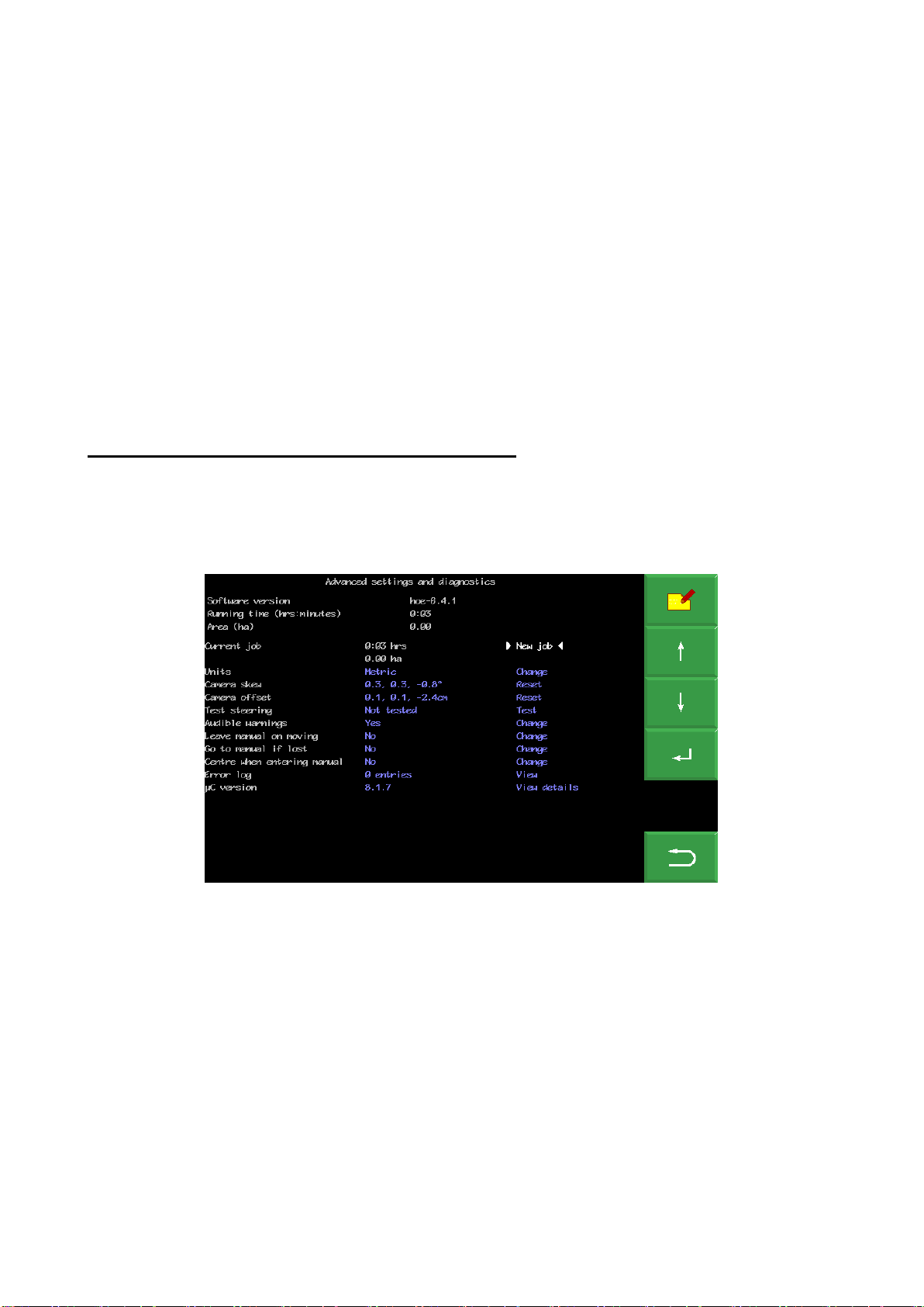
Section settings
A section is defined as a frame that has independent steering. Most implements will have only one
section. However, it is possible to have an implement with multiple independently steered
sections. This is useful when it is required to span multiple drill/transplanter bouts.
The settings are; “Width” is the width of that section and is only used to calculate area worked,
“Peak travel” which is stoke of the side shift mechanism, “Pot scale” refers to calibration of the
linear potentiometer that measures side shift position and the final setting allocates which cameras
are fitted to that section.
It is also possible to have settings (if appropriate defaults are installed) for disc steered machines.
For disc steer machines the second, third and fourth settings relate to; maximum angular deflection
from the central position, distance between the steering disc pivot axis and disc ground contact
point, and calibration of the rotary potentiometer that measures steer angle.
Configuration file “Section”standard editor screen
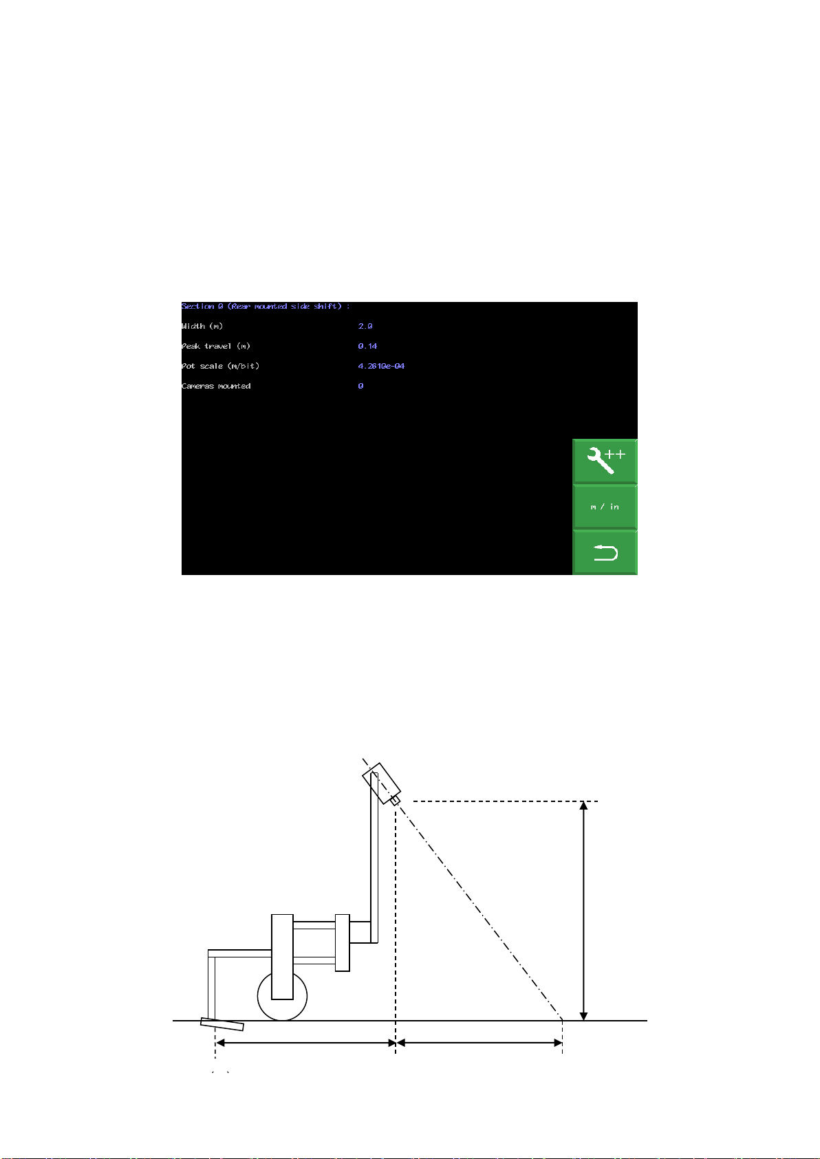
Camera settings
The first three settings relate to camera mounting geometry as illustrated below. Camera height is
the vertical distance in m (or inches with imperial units set) from ground level to the camera lens
when the implement is at its normal working height. Look ahead is the horizontal distance from a
point directly below the centre of the camera lens the centre of the image in the ground plane
(depicted by cross hairs in “manual” mode). “Distance ahead of cultivators”is the horizontal
distance in m (or inches with imperial units set) from a point vertically below the camera lens back
to the cultivator blades. (If In-row software is installed this distance is referred to as “Distance
ahead of rotors/nozzles” even if operating in inter-row mode)
“Look ahead” (m)
Height (m)
“Distance ahead of cultivators”
(m)
20
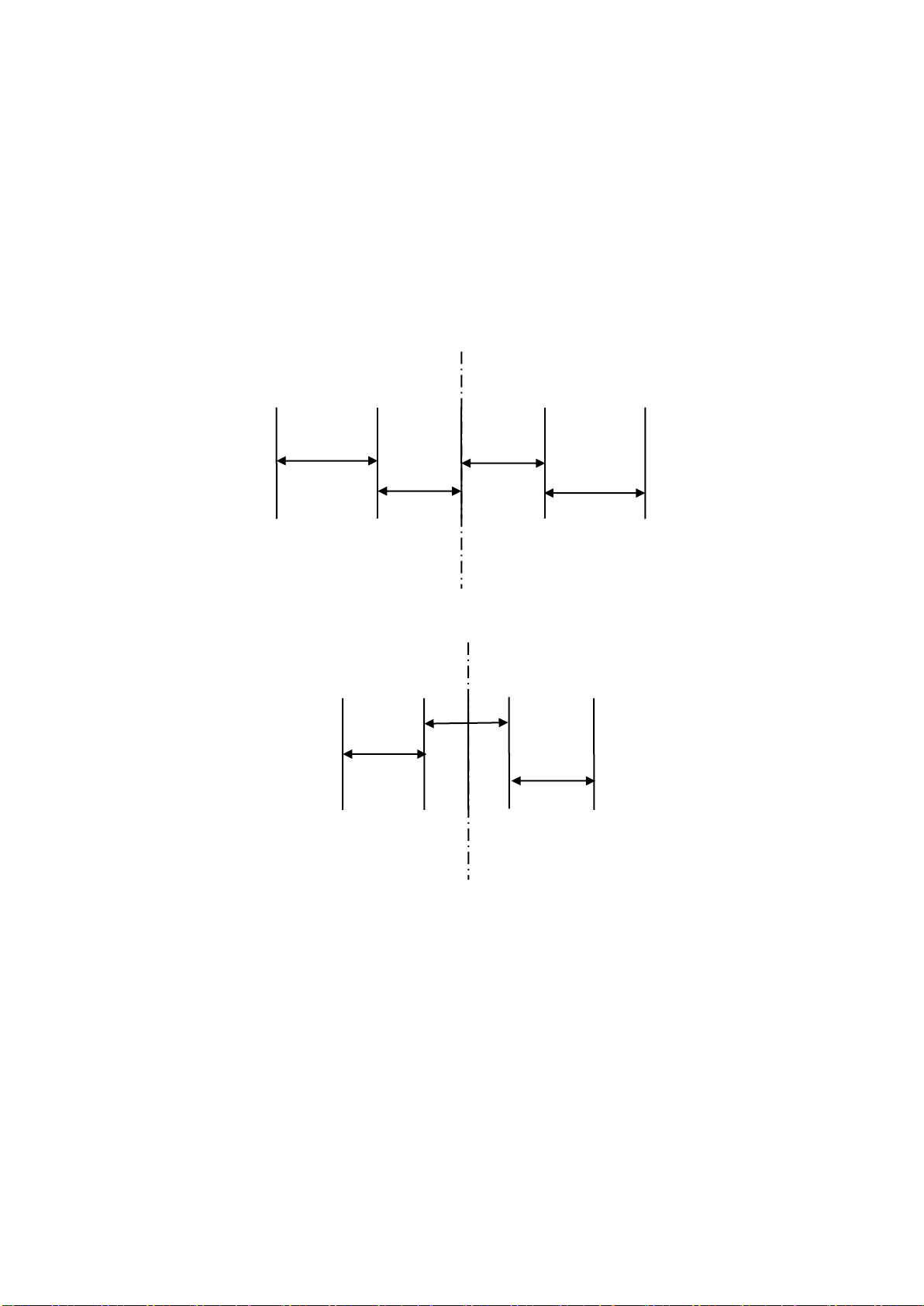
The next settings relate to what is seen in the image. The number of, and spacing between rows.
The number of rows entered here determines how many rows are used to construct the template.
Spacing between rows is normally uniform across the field of view and is therefore a single figure.
However, some crop geometries with a number of different row spacings in the same scene
require a more complex arrangement. Syntax for this is based on the assumption that the pattern
is symmetrical about the centre line and starts with the central row spacing working out to the
edge. Figures are comma delimited. In the case of an even number of rows the first figure is
always the whole row spacing, not the distance from the centre line to the next row. The following
examples cover likely configurations.
Odd no of rows irregular spacing example
Rows 5 Spacing 0.4,0.5
Even no of rows regular spacing example
Rows 4 Spacing 0.4
In the special case of following only one row the most accurate tracking will be achieved with row
spacing set to between two and three times crop foliage width with an absolute minimum of 20cm.
0.5m
0.4m
0.4m
0.5m
0.4m
0.4m
0.4m
Table of contents
Other Garford Farm Equipment manuals

Popular Farm Equipment manuals by other brands


Buhler
Buhler Round Bale Carrier 1500 Operator and parts manual

Westeel
Westeel Magnum Series Operator and installation manual

OPCOM
OPCOM OFG009 quick start guide

GREAT PLAINS
GREAT PLAINS Turbo Max 1800TM Operator's manual

GREAT PLAINS
GREAT PLAINS PL5200 Operator's manual

HMF
HMF LEOFANT 24 ABB2471 instruction manual


