Garford Robocrop Inrow Weeder Specifications

Operator Instructions

Contents
3. Overview
4. General Safety Instructions
5. Safety Signs
6. Meaning of the safety signs
7. Operating Instructions
Mounting the Robocrop InRow Weeder to the Tractor
8. Robocrop Inrow Weeder Setup Guide
10. Tine and Disc Adjustments
CE Declaration of Conformity
Garford Farm Machinery Ltd
Frognall, Deeping St James,
Peterborough PE6 8RP. United Kingdom.
Declare that the product...
Product
Model
Serial number
Year
Complies with European Directive...
2006/42/CE and 2004/108/CE
The following standards are applied ...
ISO 4254-1:2013, ISO 4254-5:2010, ISO 3767-2:2008 and ISO 11684:1995.
Garford Farm Machinery Ltd. Deeping St James.
01.01.2014
Philip Garford
Managing Director
Overview
Garford Robocrop Inrow Weeders are designed for the purpose of weed destruction, using mechanical
means, inter-row and inter-plant in transplanted vegetable crops which are planted to a stand. It may
also be possible to operate in seeded crops so long as the plants are evenly spaced and the crop is the
more dominant feature rather than the weeds.
Weed destruction is achieved by cutting through the soil with a share the depth of which is controlled at
approximately 10-20mm depth by means of a parallel linkage gauge wheel unit.
The steering of the implement and the synchronisation of the inter-plant rotors is controlled by a
computer employing image analysis of the crop just ahead of the implement in real time.
The Robocrop InRow Weeders are supplied in a range of working width and crop row width
configurations to suit customers crop configurations.
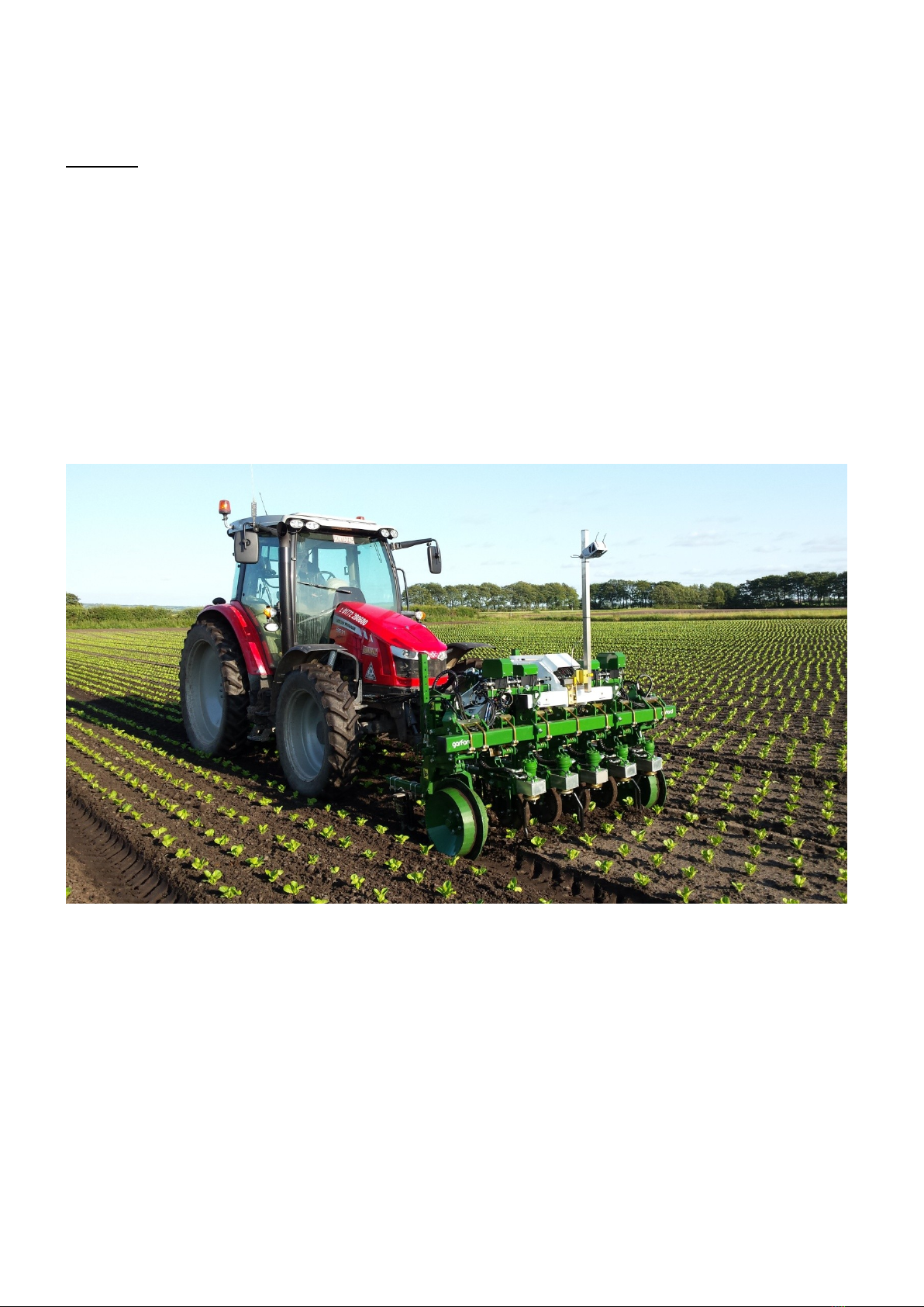
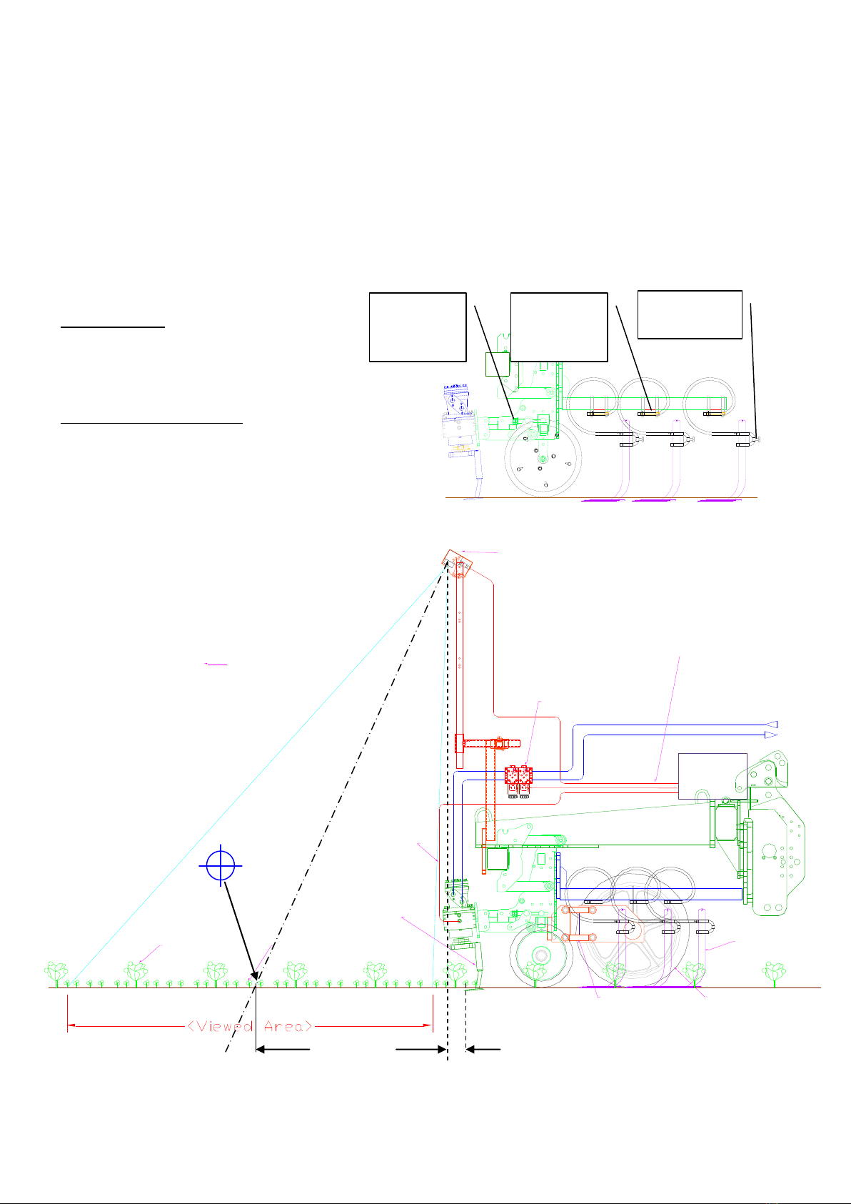
Typical employment of the Robocrop Inrow Weeder
Garford Weeding Implements
General Safety Instructions
Please read all of the safety instructions before commencing use of the implement.
Before carrying out mechanical repairs and adjustments
1. Stop the tractor engine and apply the handbrake
2. Turn off the hydraulic supply.
3. If carrying out mechanical repairs or adjustments of the implement, shut down the Robocrop computer
system and switch off the power via the rocker switch on the side of the console.
4. If the hydraulic system includes accumulators which store hydraulic pressure even when the tractor
supply is turned off, ensure the system is depressurised and allow oil to return to the tractor by
positioning the hydraulic lever in the float position. There are two pressure gauges on the hydraulic
system at the front of the implement, ensure they both read zero before carrying out repairs or
adjustments.
5. If the implement has an electric power pack, switch the isolator to the off position.
6. If possible lower the implement to the ground before working on it.
7. Never work under a raised implement unless it is supported by suitable jack stands.
8. Be aware of potential trap and shear points on the unit parallel linkages, the freeshift and the disc steer
units with self levelling, and do not put yourself at risk.
While changing settings on the computer the operator should ensure other persons do not try to make repairs
or adjustments to the implement and keep other persons well clear of the implement.
Never conduct maintenance work on the side shift or disk steering mechanisms while they are supporting the
weight of the implement.
Regularly check the condition of electric cables, hydraulic hoses and fittings and tightness of nuts and bolts etc.
If the hydraulic supply manifold is fitted with a hydraulic accumulator. Discharge the accumulator before
disconnecting the implement from the tractor.
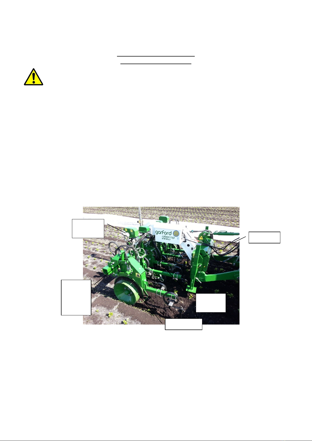
Freeshift
Disc steer
Parallel
linkages
Pressure
gauges
Parallel
linkages
with self
levelling
It is the operator’s responsibility to ensure the safety of other persons and they must not be allowed to ride on
or work near the implement when it is in operation.
The 12V power supply cables have fuses fitted near to the power plug or battery terminals. This is for short
circuit protection and must not be omitted.
When routing the loom and power supply cables ensure that they do not cause a restriction or trip point in the
cab.
Due to the bespoke nature of the design some Garford Hoes, particularly the larger size hoes, may need special
measures when travelling on highways. Lighting equipment and marker boards are available as optional extra.
Garford lighting is designed to comply with the Revised Standard for agricultural Vehicles 1st January 2016.
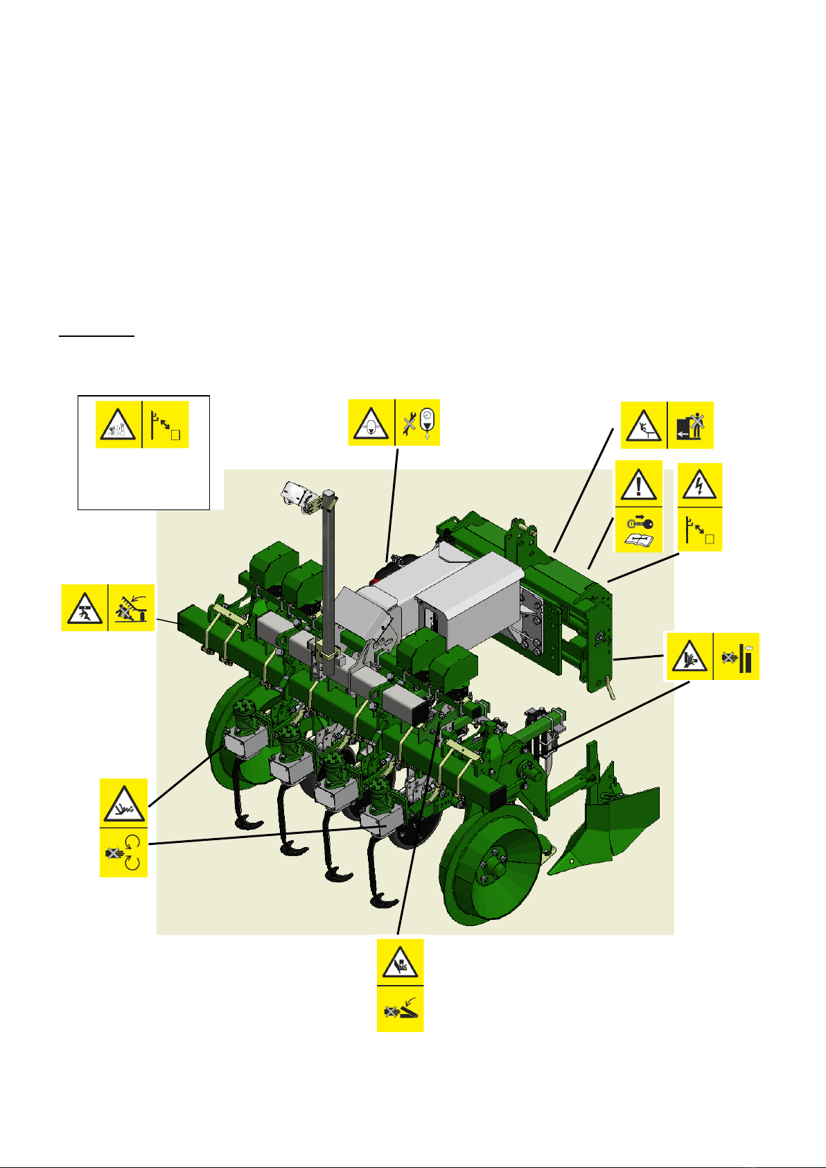
Safety Signs
Folding Frame
models only
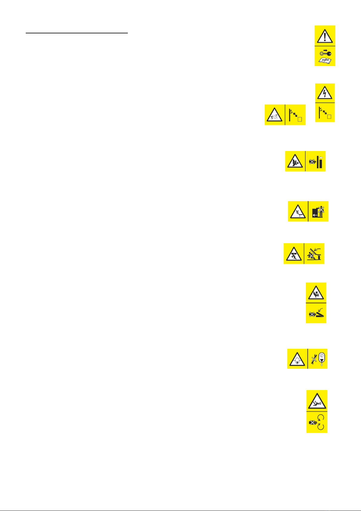
Meaning of the Safety Warning Signs
Read the operating instructions before carrying out adjustments or maintenance.
Electrical shock/Electrocution Risk. Keep sufficient distance away from electrical power lines.
Crushing risk. Keep clear of the sideshift and disc steer mechanism, folding frame points
and surrounding area during operation.
Never ride on machine during operation
Danger of crushing. Keep clear while machine is being unfolded or lowered.
Crushing risk. Keep clear of wheel unit parallel linkages during operation.
High pressure hydraulic system. Depressurise system before carrying out adjustments or
maintenance.
Powered Rotating Blade and Rotor. May rotate at anytime. Danger of entanglement

Mounting the Robocrop InRow Weeder
Never put yourself or others at risk between the tractor and implement while hitching the implement.
On a firm and level surface, hitch the implement to the tractors category 2 front 3 point linkage.
Check that the 3 point linkage has sufficient movement to raise the implement well clear of the crop when in
the field and that it will be possible to lower the implement to the soil and allow it to float on its own disc steer
support wheels.
Adjust the top link to be sure the implement is level when in the work position.
Connect the hydraulic supply lines to suitably located hydraulic supply couplings ensuring the correct direction
of flow. The supply hose is marked with a red marker and connects directly to the accumulator, the return line
is marked with a blue marker.
During work it will be necessary to lock the hydraulic supply valve of the tractor in a constant pumping position
but please ensure the supply can be stopped and pressure dumped immediately in an emergency.
It is preferable for the tractor to have a closed centre hydraulic system, however open centre systems can be
used but you may require the optional oil cooler and pressure reducer system.
Oil supply requirement is pressure of minimum of 175bar and flow of 10ltr/min + number of rows x 12ltr i.e. a 4
row machine requires 58 ltrs per minute.
Mount the console in the tractor cab in a convenient location, using the bracket supplied, where it can be easily
seen but does not obscure the operators view for safe driving. It is only necessary to glance at the console now
and again during work to reassure oneself that the system is working correctly and efficiently.
Robocrop Inrow Weeder requires 2 electrical power supply connections. The cab mounted console is fitted with
a D plug, common in most tractor cabs. The implement itself has a power cable which must be connected
directly to the tractor battery. Always take great care to observe the correct polarity - the fused side of the
supply Brown/Orange cable connects to positive, the blue cable connects to negative.
Ensure the hoses and cables are routed in such a way that they cannot chaff or become trapped or cut.

Robocrop InRow Weeder –Setup Guide
Setting up the Robocrop InRow Weeder consists of..
mechanical alignment of the weeding units
mechanical alignment of the cameras
configuration file settings
The inter relationship between all of these settings is critical; if one is wrong the weeder will not work
accurately. The accuracy of taking measurements and setting the weeder will be reflected in the accuracy of
work.
It is the operator’s responsibility to measure the crop and adjust the implement and computer settings to match
the crop.
1) The implement must be set up physically to suit the crop you are working on.
i) Set the disc steer wheel track width to suit the crop track width
ii) Set the weeder row units to suit the row widths to be worked (Always take these measurements from
the crop in the field to be worked).
iii) Ensure the rotor disc size fitted suits the crop to be worked and the setting shown on the setup
screen. The disc size should be equal to or smaller than the plant spacing to be worked. The physical
measurement across the wide part of the disc is approximately half the disc design size i.e 126mm
disc width = 25cm disc size.
Disc size designation is a special code
e.g. 16-4W6
1st part (16) is the crop spacing design size
2nd part (4) is the design offset between crop centre line and rotational axis of the disc
3rd part (W) specifies a Weeding disc, alternative =T, a Thinning disc
4th part (6) is the plant zone to be left by the disc
The numerical reference is in centimetres.
10005
8619
8614
8619
8614
8619
8614
8619
8614
8677 8677 8677 8719
8093
8091
130
8093
8091
130
8570r2
8673
8672
8673
8672
8673
8672
8673
8672
8673
8672
8673
8672
8673
8672
8673
8672
10007
9735 SL 50W
7749
7744
180
7749
7744
180
7749
7744
180
16-4W6
8543
Leg
18-4W6
8543
Leg
21-4W6
Leg
8495
25-4W7
Leg
8495
29-4W7
Leg
8495
33-4W7
Leg
8495
29-6W10
8684
Leg
33-6W10
8684
Leg
38-6W10
8684
Leg
45-6W10
8684
Leg
16-4W6 18-4W6 21-4W6 25-4W7 29-4W7 33-4W7 29-6W10 33-6W10 38-6W10 45-6W10
2) Switch on the hydraulic supply and console and allow the system to test and park the rotors.

i) Settle the weeder into the crop rows with all tractor wheels and the weeder well into the crop. You
should see the self levelling system adjust the steer discs in order to set the toolbar height. Put the 3
point linkage into the float position (never use pressure down). Adjust the top link so that the weeder
is level and the camera stem is vertical. The self levelling system monitors the position of the outside
most row unit parallel linkages to ensure the toolbar height stays a constant height above the soil
around the plants irrespective of wheeling depth or bed height. If the toolbar appears to be always
higher on one side than on the other consult your service agent.
3) Press “Setup” and check the basic settings.
i) Crop size - set to height of thickest part of foliage.
ii) Configuration –Check that the intended file is highlighted in white.
iii) Plant spacing - measure distance of 5 plant spaces and divide by 5 in at least 4 places and use the
average or set to a slightly smaller setting if it is found some plants do not get selected with a cross
while working.
iv) Clearance –start with the setting on Normal. This feature allows the non cultivated plant zone size to
be adjusted.
v) Crop Colour –set to suit the crop. If crop is a mix of red and green it may be necessary to work in
infra red mode (ask your service agent).
vi) Camera > Row quantity and width - It is the operator’s responsibility to measure the crop and adjust
the implement and computer settings to match the crop
vii) Camera > Height –settle the weeder onto the crop with all tractor wheels and the weeder well into
the crop so that everything is level. Measure the height from soil to camera lens. Check that the
height matches the setting in the configuration file. If not then adjust the camera on its bracket to the
setting shown on the console
viii) Camera > Look ahead –check that the machine is level (camera stem vertical), if not adjust the top
link of the tractor 3 point linkage until it is. Ensure that every time you enter the crop, the implement
always settles to the same position by using the 3 point linkage in the float position (never impose
pressure down from the tractor via the tractor 3 point linkage!!). With the “manual” button pressed,
measure the distance along the soil from the point directly vertically below the camera lens to the
cross hairs on the camera image. This is the look ahead distance.
ix) Camera > Ahead of rotors –the distance back from the point below the camera lens to the rotational
centre of the rotor discs. If the discs are ahead of the camera lens filter then the distance is entered
as a negative.
x) Camera > Disc Size see section 1. iii above
4) Press the “Manual” button so that the grid lines appear. Go to setup>Advanced menu and set camera skew to
zero, then return to the working screen. If the grid, for each camera, does not exactly match the crop rows,
check the camera lateral adjustment, if necessary move the camera sideways until the grid is centred. If the
overall size of the grid looks wrong go to config editor and check the Camera > focal length setting. 2008
cameras should have a 4mm lens with focal length of 0.0185mm (0.7283”) and 2009 have a 2.9mm lens with
focal length of 0.0133mm (0.5253”).
5) Check that the in work sensor is set correctly and switches the grid on and off as the implement is lowered
and raised. Check that the odometer wheel is reliably in contact with the soil and soil flow is not impeded by
tines close to the wheel.
6) Check hydraulic oil supply pressure before commencing work and during working at full speed to be sure the
oil supply is sufficient. Oil pressure should be stable and not fall below 150bar (2100psi). The return line
pressure should be near to zero, please check it, if it is more than 20 bar refer to your service agent.
Fine offset- the two central buttons facilitate adjustment of the offset. Each press of
the button will move the cutting position by 1cm.
Start with the fine offset indicator dead centre. Right/left adjustment moves the
whole implement in relation to the crop position on the camera, forward/rearward
adjustment advances or retards the rotation of the rotor disc as the implement advances forwards.
On a 2 or 3 camera machine the offset forward and backwards will only adjust the rotors that each camera is
looking at. Use the select button to choose the camera section you want to alter, the cameras always read left to
right as do the thumbnail pictures on the console.
Once you are happy that the settings and adjustments are correct, slowly advance forward into the crop. Check
the path that the weeding disc passes to ensure it is accurately centreing on the gaps between the plants and
rotating around each plant. Use the fine offset to adjust it perfectly.
Likewise check that the implement is centred left/right on the crop rows and use the fine offset to adjust
perfectly.
Hydraulic drive machines have a capability to operate at a forward speed of up to 4 plants per second and electric
drive machines at up to 6 plants per second, however quality of work and soil throw should be monitored and
speed adjusted accordingly.
Tine adjustment
The tines are adjusted laterally by the clamp
on the 50x12mm brackets and vertically via
the clamp block.
Rotor disc depth adjustment
Use the rotor depth adjuster to adjust the
cutting depth of the disc
HAPPY HOEING.
Garford Farm Machinery Ltd, Frognall, Deeping St James, Peterborough PE6 8RP United Kingdom
8635
8605
8606
8323
7832
7831
8638
8645
8644
8643
8494
8570
4. Odemeter Wheel provides
accurate measure of forward
movement and speed
Lift sensor disables
the system when the
weeder is lifted
1. The camera views the
crop ahead of the weeder
8623
8540
7749
7750
180
7749
7750
180
7749
7750
180
8730
2. Computer analyses
images from camera
3. Computer monitors
rotor position and speed
Hydraulic supply
from tractor
Inter row tines
complete the
weeding operation
5. Computer adjusts
speed of rotor via
hydraulic valve
Computer
6. Weeding rotor destroys
weeds as it loops in and
out of the plant gaps
Direction of travel
Plants Weeds
Look Ahead
Distance ahead of Rotor
8719
8673
8672
7749
7750
180
9735SL 50W
8673
8672
7749
7750
180
8673
8672
7749
7750
180
Lateral
adjustment
clamp
Vertical tine
adjustment
Rotor
depth
adjuster
Table of contents
Other Garford Farm Equipment manuals


