Garkinhall Systems GKH 575 User manual

Color Wash User Manual
V1.0
Garkinhall Systems ●P.O. Box 707 ●Franklin, TN 37065
Tel: 615-236-1000 ●Fax: 615-236-3000 ●www.maxx-tech.com
© Garkinhall Systems, Inc. 2006
All Rights Reserved
The specifications and information supplied in this document are subject to change without notice. Garkinhall Systems,
Inc. assumes no responsibility or liability for any errors or inaccuracies that may appear in this manual.
Printed in the U.S.A.

2
Important Safety Information
!
Caution: Risk of fire and electrocution. Inappropriate use may result in serious
injury or death.
•This device should be installed and maintained by qualified personnel
only.
•Read all instructions and warnings in this user manual before attempting
to use this device.
•Mains power should be properly grounded before energizing.
•Replace fuses with proper size and voltage rating only.
Eye Protection
Required
Caution: Risk of ultraviolet (UV) exposure. Looking directly at light source without
protection may cause retina damage. Do not attempt to open fixture housing
without first disconnecting power.
Garkinhall Systems, Inc. accepts no liability for damages resulting from the
failure to read and observe the warnings in this manual, unauthorized
modifications to the device, or the use of the device other than that for which it is
intended.
Trademarks
Trademarks used in this manual are the registered trademarks of Garkinhall Systems, Inc.

3
Table of Contents
Introduction ...........................................................................................................4
Setting Up .............................................................................................................5
A. Unpacking ..................................................................................................5
B. Checking the Contents...............................................................................5
C. Before Applying Power...............................................................................5
D. Applying Power ..........................................................................................7
E. Turning On the Fixture ...............................................................................7
F. Aligning the Lamp ......................................................................................7
G. Lamp Aligning Procedure...........................................................................7
H. Setting the Fixture Personality ...................................................................9
I. Personality Settings .................................................................................11
J. Setting the DMX512 Address ...................................................................23
II. Rigging the Fixture.......................................................................................25
III. Cabling the Fixture ...................................................................................26
A. Data Termination......................................................................................26
IV. Operating the Fixture ...............................................................................28
A. DMX512 Protocol .....................................................................................28
V. Troubleshooting the Fixture .........................................................................31
A. Power Check............................................................................................31
B. Data Check ..............................................................................................31
C. Fixture Check ...........................................................................................31
D. Error Messages........................................................................................32
VI. Maintenance and Cleaning.......................................................................34
VII. Technical Specifications...........................................................................35
A. Power supply............................................................................................35
B. Optical System .........................................................................................35
C. Electronics................................................................................................35
D. Mechanical ...............................................................................................36
E. Operation .................................................................................................36
VIII. Photometric Data .....................................................................................37
4
Introduction
The GKH 575 Wash from Garkinhall Systems, Inc. is an automated color wash
luminaire with RGB dichroic color mixing, an auxiliary color wheel for more
saturated colors, lenticular glass for beam shaping and a remote zoom to vary
the field angle. The optical train includes a 575-watt MSR lamp and a dichroic
glass faceted reflector for maximum efficiency. The extensive user-configurable
features allow you to set up the fixture to suit your applications, and the built-in
diagnostic features speed troubleshooting and minimize down time.
The GKH 575 Color Wash is ideally suited for a variety of applications where
soft-edge dichroic color mixing is needed, including houses of worship, live
concerts and events, permanent installations, television and production
applications.
With the proper maintenance and upkeep, the GKH 575 Wash luminaire will
provide years of service. This manual is intended as a guide to the proper set up,
operation and care of your fixture. Please read this manual, follow the
recommended procedures and keep it in a safe place for future reference.
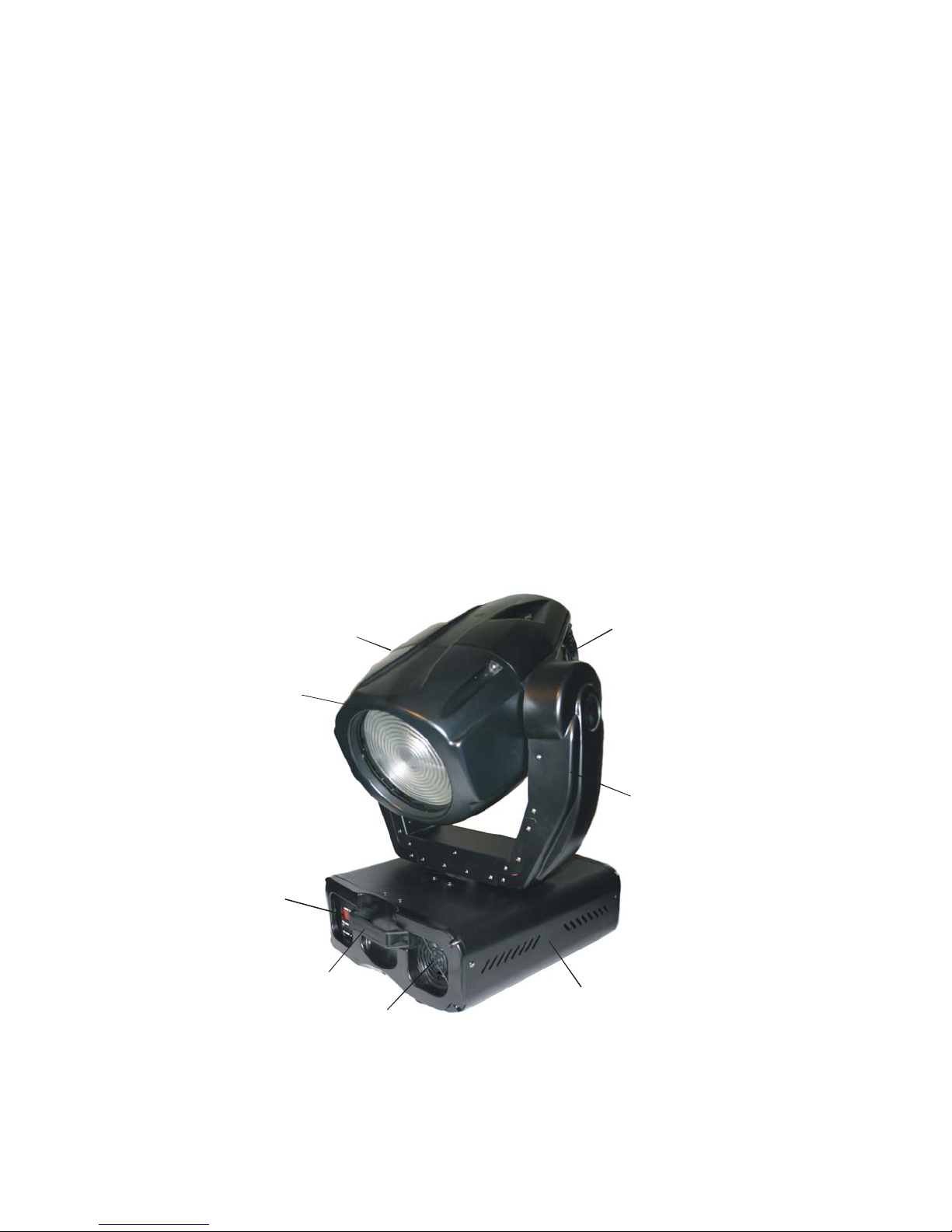
Yoke
LED Menu
Display
Head Fan
Base
Fan
Carrying Handle
Bezel

5
Setting Up
A. Unpacking
Upon receipt of your fixtures, carefully inspect the outside of the packaging and
look for any damage that may have occurred during shipping. Open the package
and carefully inspect its contents for signs of damage. Should there be any
apparent damage, notify the freight company right away. Keep all the packaging
in the event that the freight company dispatches an inspector.
B. Checking the Contents
Included in the packaging are the following items:
1. GKH 575 Color Wash luminaire
2. MDR 575 lamp
3. (2) Omega rigging brackets with quarter-turn fasteners
4. safety cable
5. User manual
C. Before Applying Power
Once you have made a visual inspection of the packaging and the fixture, you
should set it up and perform a bench test to insure that it is operating correctly.
Before applying power to the unit, make sure to follow these procedures:
1. Check to see that the voltage marked on the packaging matches that of
the power supply. In North America it should be 120V/60Hz.
2. Install the lamp.
a. Insure that the fixture is disconnected from the power source.
Caution: Surface may be extremely hot. Allow several
minutes to cool.
b. Using a Phillips screwdriver, remove the three screws on the back
of the fixture head labeled X, Y, and Z.

6
Caution: Never touch the lamp with your bare hands. The
oil from your hands can cause the quartz envelope of the
lamp to heat up and explode.
c. Without touching the lamp with your bare hands (wear gloves or
use a protective sleeve to hold the lamp), hold the ceramic base of
the lamp and insert it into the lamp socket until it is seated
completely.
d. Replace the lamp and socket assembly in the head of the fixture
and replace the three screws, X, Y and Z.
3. Install the power connector using the following wiring convention:
7
a. Green/yellow – ground
b. Blue – neutral
c. Brown – live or hot
D. Applying Power
Apply power only after the voltage has been confirmed, the lamp installed and
the connector correctly installed.
Warning: Risk of electrical shock.
E. Turning On the Fixture
Connect the fixture to a power source and turn on the red power button located
on the base of the fixture (0=off, 1=on). The fixture will automatically perform a
power-on self test. During the test, the fixture will perform a sequence of
procedures in which each of the functions will be activated, tested and homed.
The self-test will be noisy; this is normal. It will last approximately one minute,
and then the head will return to its home position and the LED display on the
base will display the default DMX512 address (001).
F. Aligning the Lamp
Before operating the fixture for the first time and each time after the lamp is
changed, it is critical that the lamp is correctly re-aligned in the reflector.
Caution: Operating the fixture without correctly aligning
the lamp in the reflector may cause damage to internal
components. Always align the lamp before operating for
the first time and each time after changing the lamp.
G. Lamp Aligning Procedure
To align the lamp, find a location with a long, clear sight line to a white wall.
Place the fixture on the floor or on a work bench and perform the following lamp
alignment procedure:
1. Turn on the fixture.
2. After it finishes the power-on self-test, the lamp should be on and
the yoke should be in the default position (pointing straight up if the
fixture is sitting on the ground or pointing straight down if the fixture
!

8
is hanging from a pipe or truss). You should be able to see a small
amount of light leak from the back of the fixture head. If the lamp is
on, skip to step 7.
3. Strike the Lamp:
a. Using the menu display function, press the [UP] or [DOWN]
button on the LED menu display several times until it reads
LAMP.
b. Press the [ENTER] button.
c. Press the [UP] or [DOWN] button until the display reads ON.
d. Press the [ENTER] button. The lamp should turn on.
NOTE: It takes approximately five minutes for the lamp to
reach its full operating temperature.
e. Press the [MODE] button to back out of the LAMP function.
4. Adjust the dimmer to full and focus the pan and tilt using the menu
display Adjust function:
a. Press the [UP] or [DOWN] button on the LED menu display
several times until the display says SPEC.
b. Press the [ENTER] button.
c. Press the [UP] or [DOWN] button several times until the
display says AdJ.
d. Press the [ENTER] button.
e. Press the [UP] or [DOWN] button several times until the
display says dinr (dimmer).
f. Press the [ENTER] button.
g. Press and hold the [UP] button until the display reaches the
number 255. If you pass it, press the [DOWN] button until it
stops at 255. The light should fade up as the dimmer opens.
h. Press the [ENTER] button.
i. Press the [UP] or [DOWN] button several times until the
display reads TILT.
j. Press the [ENTER] button.
k. Press and hold the [UP] or [DOWN] button until the fixture
head is focused on a white wall. (Rotate the fixture if
necessary or go to the PAN function and adjust the value
until it is correctly focused.)
5. Using the three lamp adjustment screws (labeled A, B, and C) in
the rear of the fixture head, adjust the lamp so that it is centered
correctly in the X, Y, and Z planes of the reflector (side-to-side and
in and out).
a. Using a 4mm (5/32”) hex wrench, turn the three screws
clockwise one revolution one at a time. Observe the spot on
the wall while adjusting the bolts.
b. If the spot appears brighter as you turn each screw, keep
adjusting them in rotation until it no longer has an
intensifying effect. If the spot appear dimmer as you turn
9
each screw, adjust them in rotation in a counterclockwise
direction until the spot is a bright as possible.
c. Adjust the screws individually so that the hot spot is in the
center of the beam.
6. Press the [MODE] button on the menu display several times to
back out of the Adjust mode. Stop when the display reads A001 (or
the assigned DMX address).
7. Reset the lamp timer to 000 (see Setting the Fixture Personality
below).
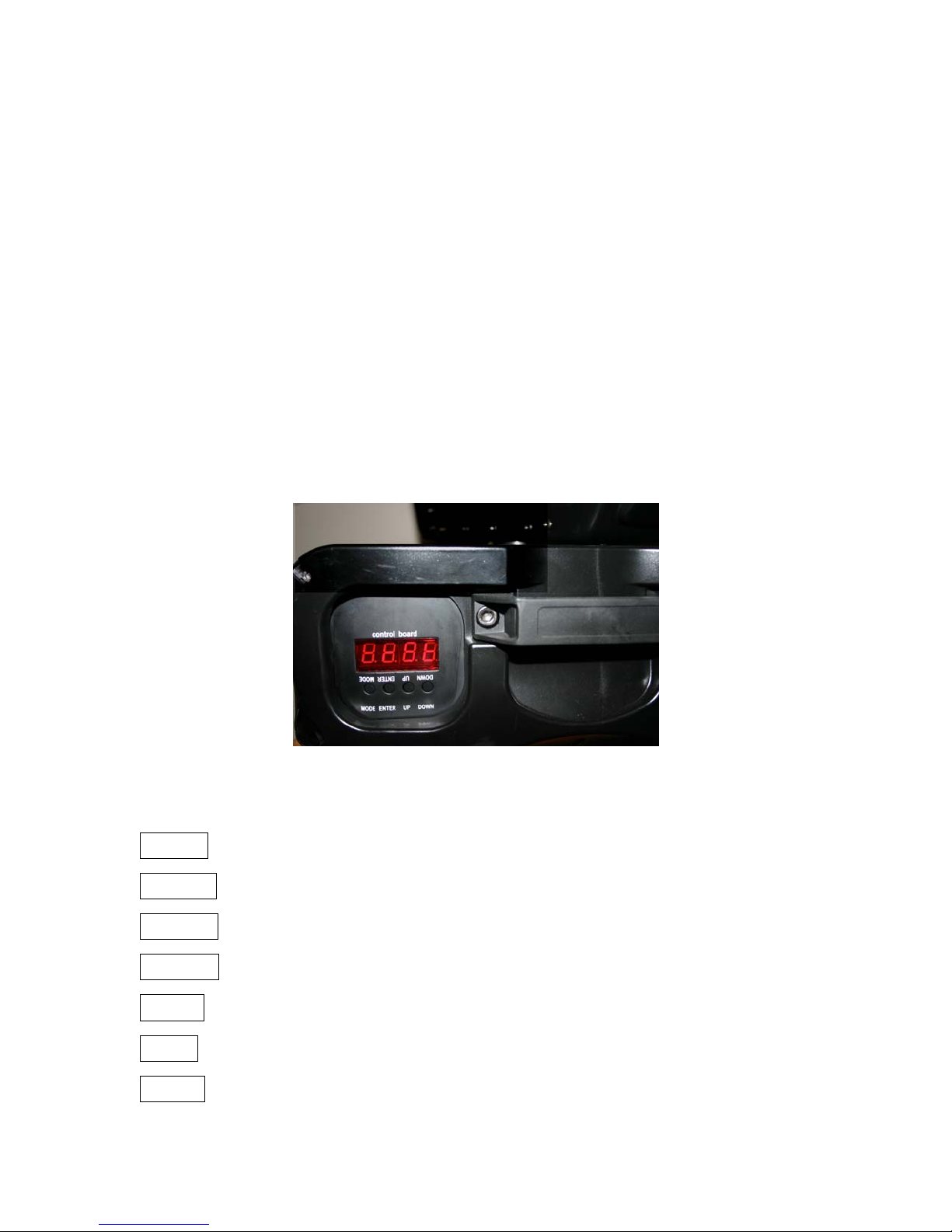
H. Setting the Fixture Personality
The GKH 575 Wash fixture has several customizable attributes that allow you to
configure the personality of the fixture to meet the requirements of your particular
application. There is an on-board menuing system in the base labeled “control
board” in which you will find a number of settings related to various aspects of
the fixture.
A map of the personality settings are outlined below and a full explanation of
each setting follows.
A001
A001 - A512
r.pAN On/Off
r.t!t on/Off
16b.r. on/Off
LAtiXXX
POti
XXX
LAMP on/Off
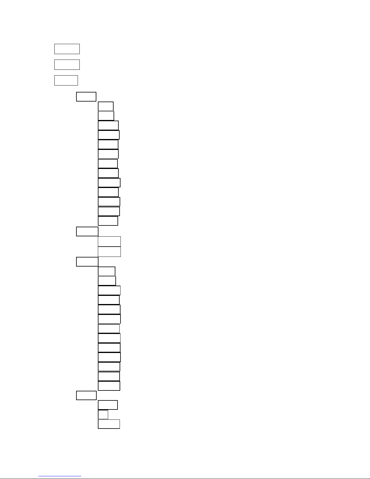
10
demo Mod.1/Mod.2
rESE.rst
SPEC
Manu
PAn – PAn.1, PAn.2, or PAn.3
t!t – t!t.1, t!t.2, or t!t.3
SPEd – SPd.1 – SPd.5
CoL.o – Co.0 – Co.9
CyAn – CYA.0 – CYA.5
MAGE – MAG.0 – MAG.5
yELL – yEL.0 – yEL.5
CSPd – CSP.1 – CSP.5
MACr. – OFF, MA. 1- MA.30
EFEC– (HOLE, SHA.1, SHA.2, SHA.3, FroS
Z.oom – Z.oo.0 – Z.oo.4
Stro. – OPEn, Str.1 – Str.9 (increasing strobe speed)
dimr – dim.0 – dim.5
LA.Au
Po0n
EnSN
dM.In –
Pan –0-255
t!t –0-255
SPEd –0-255
CoL.o –0-255
CYAn –0-255
MAGE –0-255
yELL –0-255
CSPd –0-255
MACr. –0-255
EFEC –0-255
Z.oom –0-255
Stro. –0-255
Dimr –0-255
DiSP –
turn
On –on/OFF
d.Int – 20, 40, 60, 80, 100

11
FEEd – on/off
d.L.OF – on/off
teMP – XXX
Fan.S – Lo.OF, Lo.HI, Auto, HIGH, rEG
dF.SE
AdJ. –
Pan –0-255
t!t –0-255
SPEd –0-255
CoL.o –0-255
CYAn –0-255
MAGE –0-255
yELL –0-255
CSPd –0-255
MACr. –0-255
EFEC –0-255
Z.oom –0-255
Stro. –0-255
Dimr –0-255
F.CaL –A.res
I. Personality Settings
A detailed explanation of each personality setting follows. At any time during the
processes listed below, pressing the [MODE] button will cancel the pending
setting and exit to the next highest menu level.
A001 - DMX512 Address. The current DMX512 address setting. This is
the starting address for which the fixture receives information from the controller.
To change the DMX512 address:
1. Press the [ENTER] button.
2. Press and hold the [UP] or [DOWN] button until you reach the desired
DMX512 address.
3. Press the [ENTER] button. The display should now read AXXX, where
XXX is the new DMX512 address.

12
r.PAn – Reverse pan. This setting allows you to invert the pan so that
opposing fixtures will pan in the same direction given the same command from
the controller.
To invert the pan:
1. Press the [UP] or [DOWN] button until the display reads r.Pan.
2. Press the [ENTER] button.
3. Press the [UP] or [DOWN] button until the display reads On.
4. Press the [MODE] button to get out of the r.Pan mode.
r.t!t – Reverse tilt. This setting allows you to invert the tilt so that
fixtures that are rigged inverted (e.g., hanging from a truss) will tilt in the same
direction as fixtures that are rigged upright (e.g., sitting on the floor) given the
same command from the controller.
To invert the tilt:
1. Press the [UP] or [DOWN] button until the display reads r.tilt.
2. Press the [ENTER] button.
3. Press the [UP] or [DOWN] button until the display reads On.
4. Press the [MODE] button to get out of the r.tilt mode.
16b.r. – Resolution of movement. This setting allows you to choose
between 16-bit resolution and 8-bit resolution. 16-bit resolution requires two
channels for pan (course and fine adjust) and two channels for tilt (course and
fine adjust), but it gives you 65,536 steps of resolution which translates to
smoother movement and higher target accuracy. 8-bit resolution requires only
one channel for pan and one channel for tilt, but it only gives you 256 steps of
resolution over 540 degrees of movement in the pan and 270 degrees of
movement in the tilt. That translates to about one degree per step in the tilt
function, which, over a throw distance of 35 feet, is about 8” of movement per
step. If you are concerned about having enough DMX512 channels to run all of
your fixtures, you may consider changing this function to the 8-bit setting to free
two channels per fixture.
To change the setting of the movement resolution:
1. Press the [UP] or [DOWN] button until the display reads 16b.r.
2. Press the [ENTER] button.
3. Press the [UP] or [DOWN] button until the display reads OFF.
4. Press the [ENTER] button.
5. Press the [MODE] button to get out of the 16b.r. mode.

13
LAti– Lamp timer. This setting indicates the number of hours of
operation since the lamp was installed and the lamp timer was reset.
To display the number of lamp operating hours:
1. Press the [UP] or [DOWN] button until the display reads LAti.
2. Press the [ENTER] button. The display will show four digits indicating
the lamp time in hours.
3. To reset the lamp time, press and hold the [UP] and the [DOWN]
buttons at the same time until the display reads 0000.
4. To confirm lamp hours reset, or to exit the lamp hours without resetting,
press the [ENTER] button.
5. Press the [MODE] button to get out of the LAti mode.
POti – Power time. This setting indicates the total number of hours of
operation of the fixture. It is non-resettable.
To display the number of hours of operation:
1. Press the [UP] or [DOWN] button until the display reads POti.
2. Press the [ENTER] button. The display will show four digits indicating
the number of hours the fixture has been used. This is a non-resettable
function.
3. To exit, press the [ENTER] button.
4. Press the [MODE] button to get out of the Poti mode.
LAMP – Lamp on/off. This setting allows you to manually turn the lamp on
or off from the menu display.
To manually turn the lamp on:
1. Press the [UP] or [DOWN] button until the display reads LAMP.
2. Press the [ENTER] button.
3. Press the [UP] or [DOWN] button until the display reads ON.
4. Press the [ENTER] button. The lamp will turn on.
5. Press the [MODE] button to get out of the LAMP mode.
dEMo – Demonstration mode. This setting allows you to demonstrate the
features of the fixture without the use of a controller. There are two demo modes:

14
mode 1 and mode 2. Mode 1 does not change the pan and tilt settings but cycles
through all the other attributes of the fixture. Mode 2 changes all of the attributes
of the fixture, including pan and tilt, in sequence.
To put the fixture in demonstration mode 1:
1. Press the [UP] or [DOWN] button until the display reads deMo.
2. Press the [ENTER] button.
3. Press the [UP] or [DOWN] button until the display reads Mod.1.
4. Press the [ENTER] button.
5. Press the [UP] or [DOWN] button until the display reads PAn.
6. Press the [ENTER] button. The display will read a value between 0 and
255 indicating the current pan position of the head.
7. Press the [UP] or [DOWN] button until the fixture is panned to the
desired position.
8. Press the [ENTER] button.
9. Press the [UP] or [DOWN] button until the display reads t!t.
10. Press the [ENTER] button. The display will read a value between 0
and 255 indicating the current tilt position of the head.
11. Press the [UP] or [DOWN] button until the fixture is tilted to the
desired position.
12. Press the [ENTER] button.
13. Press the [UP] or [DOWN] button until the display reads Z.oom.
14. Press the [ENTER] button. The display will read a value between 0
and 255 indicating the current zoom value.
15. Press the [UP] or [DOWN] button until the zoom is at the desired
position.
16. Press the [ENTER] button.
17. Press the [UP] or [DOWN] button until the display reads Go...
18. Press the [ENTER] button. The display will read run, the shutter will
open, and the fixture will begin executing a sequence demonstrating its
features.
19. To exit the demonstration mode, press the [MODE] button twice.
To put the fixture in demonstration mode 2, follow the procedure above and
choose the Mod.2 option.
rESE. – Reset. This setting can be used to reset all the functions of the
fixture. Should any of the attributes become misaligned or if there is an error, it is
a good idea to reset the fixture to see if the problem goes away.
To reset the fixture:
1. Press the [UP] or [DOWN] button until the display reads rESE..

15
2. Press the [ENTER] button. The display will read rSt and the fixture will
reset and begin a self-test sequence. When the fixture resets, the motors
will make some noise. This is normal. Once the entire self-test sequence
has been completed, the fixture will return to the previous setting and the
display will read AXXX, where XXX is the DMX512 address for which it
has been set.
SPEC – Special functions. This setting allows you to access a variety of
useful functions including manual control, lamp operation, DMX512 input
monitoring, display settings, position encoding, temperature monitoring, fan
settings, and calibration. The specific functions are outlined below.
To access the special functions menu and submenus:
1. Press the [UP] or [DOWN] button until the display reads SPEC.
2. Press the [ENTER] button.
3. Press the [UP] or [DOWN] button until you reach the desired function
listed below.
4. Press the [ENTER] button. The instructions for each function are listed
below.
MAnu – Manual operation. This setting allows you to manually recall
factory presets for every function of the luminaire including pan, tilt, speed
of movement, color wheel, magenta, cyan and yellow color mixing, speed
of color change, macros, effects, zoom, strobe and dimming. The
attributes can be set one at a time by selecting the MAnu option from the
SPEC function of the display (see SPEC above) and choosing from the
available options below:
PAn – Choose one of three pan focus settings listed below by
using the [UP] and [DOWN] buttons until the display reads PAn,
and then pressing the [ENTER] button. Use the [UP] and [DOWN]
buttons to select the desired pan setting (PAn.1, PAn.2, or PAn.3),
then press [ENTER]. The display will then go back to the next
highest menu level.
t!t – Choose one of three tilt position settings listed below by
using the [UP] and [DOWN] buttons until the display reads t!t,
and then pressing the [ENTER] button. Use the [UP] and [DOWN]
buttons to select the desired tilt setting (t!t.1, t!t.2, or t!t.3),
then press [ENTER]. The display will then go back to the next
highest menu level.

16
SPEd (speed)– Choose one of five speed of movement settings
listed below by using the [UP] and [DOWN] buttons until the
display reads SPEd, and then pressing the [ENTER] button. Use
the [UP] and [DOWN] buttons to select the desired speed setting
(SPd.1 – SPd.5), then press [ENTER]. The display will then go
back to the next highest menu level.
CoL.o (color) – Choose one of ten color wheel settings listed below
by using the [UP] and [DOWN] buttons until the display reads
CoL.o, and then pressing the [ENTER] button. Use the [UP] and
[DOWN] buttons to select the desired color setting (Co.0 – Co.9),
then press [ENTER]. The display will then go back to the next
highest menu level.
CyAn – Choose one of six cyan color settings listed below by using
the [UP] and [DOWN] buttons until the display reads CYan, and
then pressing the [ENTER] button. Use the [UP] and [DOWN]
buttons to select the desired cyan setting (CYA.0 – CYA.5), then
press [ENTER]. The display will then go back to the next highest
menu level.
MAGE (magenta) – Choose one of six cyan color settings listed
below by using the [UP] and [DOWN] buttons until the display
reads MAGE, and then pressing the [ENTER] button. Use the [UP]
and [DOWN] buttons to select the desired magenta setting (MAG.0
– MAG.5), then press [ENTER]. The display will then go back to the
next highest menu level.
yELL (yellow) – Choose one of six yellow color settings listed
below by using the [UP] and [DOWN] buttons until the display
reads yELL, and then pressing the [ENTER] button. Use the [UP]
and [DOWN] buttons to select the desired yellow setting (yEL.0 –
yEL.5), then press [ENTER]. The display will then go back to the
next highest menu level.
CSPd (color speed) – Choose one of five color-changing speed
settings listed below by using the [UP] and [DOWN] buttons until
the display reads CSPd, and then pressing the [ENTER] button.
Use the [UP] and [DOWN] buttons to select the desired color-
changing speed setting (CSP.1 – CSP.5), then press [ENTER]. The
display will then go back to the next highest menu level.
MACr. (macro) – There are 30 macros built into the fixture memory.
These macros may be accessed manually using the manual
operation feature of the SPEC menu. Choose one of 30 macro
settings listed below by using the [UP] and [DOWN] buttons until

17
the display reads MACr., and then pressing the [ENTER] button.
Use the [UP] and [DOWN] buttons to select the desired macro
setting (OFF, MA. 1 – MA.30), then press [ENTER]. The display will
then go back to the next highest menu level. To turn off the macros,
select the OFF setting using the same procedure as above and
press the [ENTER] button.
EFEC (effects) – Choose one of four effect settings listed below by
using the [UP] and [DOWN] buttons until the display reads EFEC,
and then pressing the [ENTER] button. Use the [UP] and [DOWN]
buttons to select the desired effect [HOLE (open – no effect);
SHA.1 – SHA.3 (three beam shaping effects); FroS (frost)], then
press [ENTER]. The display will then go back to the next highest
menu level.
Z.oom – Choose one of five zoom settings listed below by using the
[UP] and [DOWN] buttons until the display reads Z.oom, and then
pressing the [ENTER] button. Use the [UP] and [DOWN] buttons to
select the desired zoom setting (Z.oo.0 – Z.oo.4), then press
[ENTER]. The display will then go back to the next highest menu
level.
Stro. (strobe) – Choose one of nine strobe settings (plus no
strobe) listed below by using the [UP] and [DOWN] buttons until
the display reads Stro., and then pressing the [ENTER] button.
Use the [UP] and [DOWN] buttons to select the desired strobe
setting [OPEn (no strobe); Str.1 – Str.9 (increasing strobe
speed)], then press [ENTER]. The display will then go back to the
next highest menu level.
dimr (dimmer) – Choose one of six dimmer settings listed below
by using the [UP] and [DOWN] buttons until the display reads
dimr, and then pressing the [ENTER] button. Use the [UP] and
[DOWN] buttons to select the desired dimmer setting (dim.0 –
dim.5), then press [ENTER]. The display will then go back to the
next highest menu level.
LA.Au – Lamp Auto function. This function allows you to set the lamp
to come on when the fixture is turned on. It also allows you to bypass the
lamp on sensor for emergency operation in the event that the sensor fails.
To set up the fixture so that the lamp automatically turns on when the
fixture is powered on:
1. Select the LA.Au option from the SPEC function of the display
(see SPEC above).

18
2. Press the [ENTER] button.
3. Press the [UP] or [DOWN] button until the display reads Po0n.
4. Press the [ENTER] button.
5. Press the [UP] or [DOWN] button until the display reads on.
4. Press the [ENTER] button.
5. Press the [MODE] button twice to back out of the special
functions mode.
If the auto lamp on function is set to off, then the lamp will stay off until
the fixture receives a lamp on signal from the controller or until the lamp is
turned on manually through the menu operation.
In the fixture head there is a photoreceptor that is used to detect the
presence or absence of light. The purpose of this light sensor is to prevent
the ignitor from damaging the lamp circuit by continually trying to ignite the
lamp if it is already on or if the lamp is unable to turn on. The lamp light
sensor can be turned off in the event that the sensor is non-functional so
that the fixture may be used in emergency situations.
Note: If the En.Sn. function has been turned Off then the heat
error message will only appear if the lamp has been turned off from
the controller or the menu display and turned back on within five
minutes. It will not automatically detect a lamp off condition should
the lamp extinguish by itself.
To turn the lamp light sensor off:
1. Select the LA.Au option from the SPEC function of the display
(see SPEC above).
2. Press the [ENTER] button.
3. Press the [UP] or [DOWN] button until the display reads EnSn.
4. Press the [ENTER] button.
5. Press the [UP] or [DOWN] button until the display reads off.
4. Press the [ENTER] button.
5. Press the [MODE] button twice to back out of the special
functions mode.
Caution: In the event that the
En.Sn.
function has been turned
off
and the lamp extinguishes by itself, then the software will not
prevent the ignition of the lamp within the five minute window or if
the lamp fails to ignite within 28 seconds of attempting to turn it on.
Damage may occur from the high voltage ignition should the fixture
receive repeated lamp on commands.
dM.In – DMX input monitor. This function allows you to read the
current DMX512 signal input value for each attribute. It is a valuable

19
troubleshooting tool that can be used to confirm the integrity of the input
control signal and rule out problems with DMX addressing, controller
output, and cabling problems in the event of a failure.
To check the DMX512 input value of a particular attribute:
1. Select the dM.In option from the SPEC function of the display
(see SPEC above).
2. Press the [ENTER] button.
3. Press the [UP] or [DOWN] button to select an attribute to
monitor. The options are: pan (PAn), tilt (t!t), speed of movement
(SPEd), color wheel (CoL.o), cyan (CYAn), magenta (MAGE),
yellow (yELL), color change speed (CSPd), macros (MACr.),
effects (EFEC), zoom (Z.oom), strobe (Stro.), and dimmer
(dimr).
4. Press the [ENTER] button. The display will show the current
input value in the range of 0 – 255.
5. Press the [MODE] button twice to back out of the special
functions mode.
DiSP – Display functions. This function allows you to set up the LED
menu display according to your needs. There are three attributes of the
display that may be adjusted: the orientation of the display (upside down
or right side up), whether the display is on or off, and the intensity of the
display.
turn The orientation of the display may be changed in order to
suit the application. If the fixture is rigged from a structure in an
upside down orientation, then it is advantageous to invert the
display so that it will be easier to read.
To invert the display:
1. Select the DiSP option from the SPEC function of the display
(see SPEC above).
2. Press the [ENTER] button.
3. Press the [UP] or [DOWN] button until the display reads turn.
4. Press the [ENTER] button. The display will invert.
5. Press the [MODE] button twice to back out of the special
functions mode.
on The display may be set to the off position in the event that the
fixture is visible to the audience and the red LED light is a
distraction.

20
To turn the menu display off:
1. Select the DiSP option from the SPEC function of the display
(see SPEC above).
2. Press the [ENTER] button.
3. Press the [UP] or [DOWN] button until the display reads On.
4. Press the [ENTER] button.
5. Press the [UP] or [DOWN] button until the display reads OFF.
6. Press the [ENTER] button. The display will turn off in two
minutes.
7. Press the [MODE] button twice to back out of the special
functions mode.
When the menu display is off, it will turn back on when any button
on the menu display is pressed. It will stay on for two minutes after
the last button press and then turn off again.
d.Int Display intensity setting. This setting allows you to set the
intensity of the display in five increments of 20%.
To change the intensity setting of the display:
1. Select the d.Int option from the SPEC function of the display
(see SPEC above).
2. Press the [ENTER] button.
3. Press the [UP] or [DOWN] button to select the desired value of
intensity (20%, 40%, 60%, 80% or 100%).
4. Press the [ENTER] button.
5. Press the [MODE] button twice to back out of the special
functions mode.
FEEd – Position feedback. This setting allows you to turn on or off
the position encoder that automatically repositions the yoke in the event
that it is bumped or moved.
To turn the position encoder off:
1. Select the FEEd option from the SPEC function of the display
(see SPEC above).
2. Press the [ENTER] button.
3. Press the [UP] or [DOWN] button until the display reads OFF.
4. Press the [ENTER] button.
5. Press the [MODE] button twice to back out of the special
functions mode.
Table of contents


