Garmin AS-350 Series User manual

Garmin ATTM is a trademark of Garmin Ltd. or its subsidiaries.
Printed in the USA
GDL 90 System
Instructions for Continued Airworthiness
Helicopter STC
(AS-350 Series)
Part Number: 560-0255-00
Document Revision: A
21 December 2005
Garmin AT, Inc.
2345 Turner Rd SE
Salem, OR 97302 USA
Phone (503) 581-8101
FAX (503) 364-2138

GDL 90 System ICA, Helicopter STC
Garmin AT
2345 Turner Rd SE 21 December 2005
Salem, OR 97302 Part #: 560-0255-00 Rev A
©Copyright 2005 Garmin AT All Rights Reserved Page 2 of 13
Revision Log
Rev Date Description EN By
A 21 Dec 2005 Initial release, MS Word 2002 8297 MAK
Garmin AT, Inc. Cage Code
OXCJ6 2345 Turner Road SE
Salem, Oregon USA
Title: GDL 90 System Instructions for
Continued Airworthiness, Helicopter
STC
Number: 560-0255-00
Prepared by: Marvin A. Kumley
Date: 21 December
2005
Approved
by: Thomas L. Mosher
Tom Mosher GDL 90 Project Manager
Date: 22 Dec 2005

GDL 90 System ICA, Helicopter STC
Garmin AT
2345 Turner Rd SE 21 December 2005
Salem, OR 97302 Part #: 560-0255-00 Rev A
©Copyright 2005 Garmin AT All Rights Reserved Page 3 of 13
Table of Contents
1INTRODUCTION...............................................................................................................................................4
1.1 DOCUMENT REVISION &DISTRIBUTION PROCESS..............................................................................................4
1.2 AIRWORTHINESS LIMITATIONS SECTION (ALS)......................................................................................................4
1.3 PERMISSION TO USE CERTAIN DOCUMENTS ..........................................................................................................4
1.4 ASSISTANCE.........................................................................................................................................................4
2INSTRUCTIONS FOR CONTINUED AIRWORTHINESS ..........................................................................5
2.1 INTRODUCTION....................................................................................................................................................5
2.2 DESCRIPTION OF ALTERATION..............................................................................................................................6
2.3 CONTROL,OPERATING INFORMATION ..................................................................................................................8
2.4 SERVICING INFORMATION ....................................................................................................................................8
2.5 PERIODIC MAINTENANCE INSTRUCTIONS ..............................................................................................................8
2.5.1 Equipment Calibration ..............................................................................................................................8
2.5.2 GDL 90 Battery Replacement....................................................................................................................8
2.5.3 Cleaning the GSL 71 Front Panel.............................................................................................................9
2.5.4 Altitude Encoder Calibration ....................................................................................................................9
2.6 OVERHAUL PERIOD .............................................................................................................................................9
2.7 TROUBLESHOOTING INFORMATION.......................................................................................................................9
2.8 REMOVAL AND REPLACEMENT INFORMATION........................................................................................................9
2.9 GENERAL PROCEDURAL INSTRUCTIONS ..............................................................................................................10
2.10 DIAGRAMS.........................................................................................................................................................11
2.11 SPECIAL INSPECTION REQUIREMENTS.................................................................................................................12
2.12 APPLICATION OF PROTECTIVE TREATMENTS ........................................................................................................12
2.13 DATA RELATIVE TO STRUCTURAL FASTENERS .......................................................................................................12
2.14 SPECIAL TOOLS .................................................................................................................................................12
2.15 ADDITIONAL INSTRUCTIONS FOR ROTORCRAFT OPERATING UNDER FAR 121/135 ...............................................12
2.16 IMPLEMENTATION AND RECORD KEEPING ..........................................................................................................12
List of Figures and Tables
FIGURE 1–SAMPLE GDL 90 SYSTEM ............................................................................................................................6
FIGURE 2. GSL 71 FRONT PANEL ..................................................................................................................................7
TABLE 1: GDL 90 SYSTEM COMPONENTS ......................................................................................................................7
TABLE 2. UNIT WEIGHTS.............................................................................................................................................11
TABLE 3. UNIT CENTER OF GRAVITY...........................................................................................................................11
TABLE 4. UNIT POWER LOADS.....................................................................................................................................11

GDL 90 System ICA, Helicopter STC
Garmin AT
2345 Turner Rd SE 21 December 2005
Salem, OR 97302 Part #: 560-0255-00 Rev A
©Copyright 2005 Garmin AT All Rights Reserved Page 4 of 13
1Introduction
This document contains Instructions for Continued Airworthiness (ICA) compliant with 14 CFR
27.1529 and Part 27 Appendix A requirements. The ICA includes information required by the
operator to adequately maintain the GDL 90 system. This system has built-in-self test features
and fault annunciation that notify the pilot in the event of system component failure. This
document refers to other documents for specific information that is either part of the installation
package or an existing part of the aircraft’s permanent record.
1.1 Document Revision & Distribution Process
ICA revisions must be submitted for ACO approval. The ACO will obtain AEG acceptance, and
issue evidence of approval. After ACO approval, Garmin AT will release the revised ICA for
customer use, and provide any required notification of the revision.
The latest revision of this document is distributed on the GDL 90 UAT Sensor Product CD
(Garmin AT P/N 140-0063-xxx), shipped with each new GDL 90 or GSL 71 unit. The latest
revision is also available on the Garmin website (Garmin.com). A Garmin Service Letter,
describing ICA revision, will be sent to dealers and/or GDL 90 or GSL 71 owners of record if
revision is determined to be significant.
1.2 Airworthiness Limitations Section (ALS)
The airworthiness limitations section is FAA approved and specifies inspections and other
maintenance required under §43.16 and §91.403 of the Federal Aviation Regulations (FAR)
unless an alternative program has been FAA approved.
There are no mandatory replacement times for the GDL 90 or GSL 71 in this STC installation.
There are no mandatory structural inspections associated with this STC.
See Rotorcraft Flight Manual Supplement (as detailed in the Master Drawing List listed in
Section 2.1) for system limitations.
1.3 Permission to use Certain Documents
Permission is granted to any corporation or person applying for approval of a Garmin GDL 90 or
GSL 71 installation to use and reference appropriate STC documents to accomplish the
Instructions for Continued Airworthiness and show compliance with STC engineering data. If
desired, the data within this document may be reformatted and used by the installing agency of
the Garmin GDL 90 or GSL 71 in a comprehensive ICA for the rotorcraft.
1.4 Assistance
Flight Standards Inspectors or the certificate holder’s PMI have the required resources to
respond to questions regarding this ICA. In addition, the customer may refer questions regarding
this equipment and it’s installation to the manufacturer, Garmin AT. Garmin AT customer
assistance may be contacted during normal business hours via telephone or email.

GDL 90 System ICA, Helicopter STC
Garmin AT
2345 Turner Rd SE 21 December 2005
Salem, OR 97302 Part #: 560-0255-00 Rev A
©Copyright 2005 Garmin AT All Rights Reserved Page 5 of 13
2Instructions for Continued Airworthiness
2.1 Introduction
Content, Scope, Purpose and
Arrangement: This document identifies the Instruction for Continued
Airworthiness for installation of the Garmin GDL 90
System.
Applicability: Applies to rotorcraft altered by installation of the Garmin
GDL 90 System.
Definition of Abbreviations: AEG – Aircraft Evaluation Group
ALS – Airworthiness Limitations Section
BIT – Built-In-Test
FSDO – Flight Standards District Office
GPS – Global Positioning System
ICA – Instructions for Continued Airworthiness
PMI – Principal Maintenance Inspector
POI – Principal Operation Inspector
STC – Supplemental Type Certificate
UAT – Universal Access Transceiver
Precautions: N/A, None
Units of measurement: N/A, None
Referenced publications:
(or later FAA-approved revisions) Garmin AT documents:
GDL 90 System Helicopter Master Data List 560-0254-00
Rev A
GDL 90 Installation Manual 560-1049-01 Rev A
GDL 90 System Helicopter Installation Manual Supplement
561-0290-00 Rev A
GDL 90 Maintenance Manual 560-7031-00 Rev. -
A-33 GPS Antenna Install Guide 560-0949-01 Rev. C
A-34 GPS Antenna Install Guide 560-5047-00 Rev. C
A-41 UAT Antenna Install Manual 560-0215-04 Rev. B
A-40 UAT Antenna Install Manual 560-0253-00 Rev. –
For installations including the GSL 71:
GSL 71 Pilot’s Guide 560-0410-00 Rev B
GSL 71 Install Manual 560-0411-00 Rev B
GSL 71 RFM Supplement 560-0412-00 Rev A
Retention: This document, or the information contained within, should
be retained in the permanent rotorcraft record.

GDL 90 System ICA, Helicopter STC
Garmin AT
2345 Turner Rd SE 21 December 2005
Salem, OR 97302 Part #: 560-0255-00 Rev A
©Copyright 2005 Garmin AT All Rights Reserved Page 6 of 13
2.2 Description of Alteration
Installation of the Garmin GDL 90 Data Link Sensor with UAT antenna, GPS/WAAS antenna,
and other system interfaces. The GDL 90 can interface to the pilot through optional existing
equipment, such as the Garmin MX20 Multi-Function Display. Altitude data can be provided
directly to the GDL 90 as shown in Figure 1, or through other compatible interfaced equipment,
such as the MX20. The GDL 90 UAT may also interface to the pilot through the optional GSL
71 UAT Control Panel, which may be installed under this STC.
Figure 1 – Sample GDL 90 System
GDL 90 System ICA, Helicopter STC
Garmin AT
2345 Turner Rd SE 21 December 2005
Salem, OR 97302 Part #: 560-0255-00 Rev A
©Copyright 2005 Garmin AT All Rights Reserved Page 7 of 13
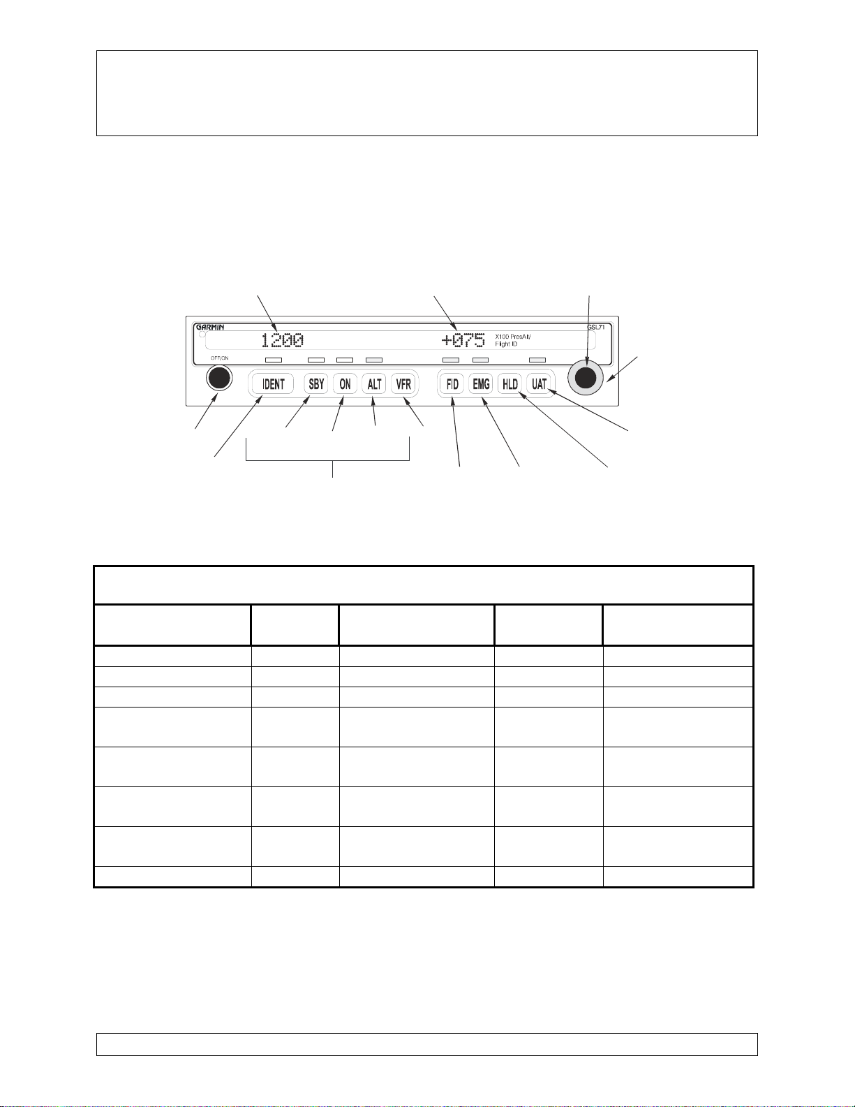
The Garmin GSL 71 is an optional control panel for the GDL 90 UAT datalink. It is certified
under TSO C154. The GSL 71 can control the GDL 90 and provide the operational status of
the GDL 90. The GSL 71 can provide data to the GDL 90 for transmission via the UAT
datalink. This data may include a Flight ID code, or other Rotorcraft status information
including ADS-B position data.
S
quaw
k
Code Altitude
Display
S
mall, Inner
Knob
Large, Out er
Knob
UAT St at us
AltitudeHold
Alerter
Emergency
Flight ID
VFR
Select
ModeSelect
Standby On Altitude
On
Ident
Power
Figure 2. GSL 71 Front Panel
The GDL 90 System components for this installation are listed in Table 1.
Table 1: GDL 90 System Components
Description Model
No. Mfg. P/N Mfg. Comment
Data Link Sensor GDL 90 430-6081-100-xxx Garmin AT
UAT Control Panel GSL 71 430-6090-6xx Garmin AT Optional
Micro APM 430-6200-0xx Garmin AT
GPS Antenna A-33 590-1104
AT-575-9 Garmin AT
AeroAntenna Standard antenna
GPS Antenna A-34 590-1112
AT-575-93 Garmin AT
AeroAntenna Optional “teardrop”
footprint
UAT Antenna A-40 590-0052
CI 105-11 Garmin AT
Comant Standard antenna
UAT Antenna A-41 590-0051
AT-130-2 Garmin AT
AeroAntenna Optional antenna
Connections are made to the following existing rotorcraft equipment:
•Power Bus
•Serial Data Interfaces (to previously-installed or concurrently-installed equipment)
•Audio Panel or Speaker (optional)

GDL 90 System ICA, Helicopter STC
Garmin AT
2345 Turner Rd SE 21 December 2005
Salem, OR 97302 Part #: 560-0255-00 Rev A
©Copyright 2005 Garmin AT All Rights Reserved Page 8 of 13
2.3 Control, Operating Information
The GDL 90 does not have a direct pilot interface. If the GDL 90 is interfaced to optional
external controllers or display systems, consult the appropriate controller or display User’s
Guide for system operation and self-test information. If an external controller is used other than
the GSL 71 or the MX20 MFD the system includes an external GDL 90 failure annunciator.
Some GDL 90 UAT Data Link Sensor units are controlled by the optional GSL 71. Consult the
GSL 71 User’s Guide listed in Section 2.1 of this document for system operation and self-test
information for GSL 71 installations.
Rotorcraft-specific configuration information for the GDL 90 is stored in the MicroAPM. This
information may be accessed using a PC as described in the GDL 90 Installation Manual listed in
Section 2.1 of this document.
2.4 Servicing Information
None. In the event of system failure, return the unit to the manufacturer or an approved repair
station.
2.5 Periodic Maintenance Instructions
The GDL 90 is designed to detect internal failures. A thorough self-test is executed
automatically upon application of power, and built-in test is continuously executed. Detected
errors are indicated by failure LEDs on the GDL 90, and maintenance is on-condition. If the
GDL 90 is interfaced to an optional external controller or MFD, detected errors may also be
indicated by annunciation on the interfaced controller or MFD.
The GSL 71 UAT Control Panel is also designed to detect internal failures. A self-test is
executed automatically upon application of power, and built-in test is continuously executed.
Detected errors at start-up are indicated by “TEST” “FAIL” on the GSL 71 LED display.
Detected errors during use are indicated by “UAT” “FAIL” on the display. At an aircraft annual
inspection, conduct a visual inspection on the GSL 71 UAT Control Panel and its wire harness to
insure continued installation integrity. Visually inspect wiring harness to insure no chafing or
wire routing problems.
At an aircraft annual inspection, conduct a visual inspection on the GDL 90 Data Link Sensor,
GSL 71 Control Panel, and their wire harness to insure continued installation integrity. Visually
inspect wiring harness to insure no chafing or wire routing problems. The MicroAPM is
installed in the wiring harness near the GDL 90 unit.
2.5.1 Equipment Calibration
The GDL 90 and GSL 71 designs require no adjustments or calibration.
2.5.2 GDL 90 Battery Replacement
The GDL 90 has an internal keep-alive battery that will last about 10 years. The battery is
used for retention of internal ram memory data and GPS system information. Regular

GDL 90 System ICA, Helicopter STC
Garmin AT
2345 Turner Rd SE 21 December 2005
Salem, OR 97302 Part #: 560-0255-00 Rev A
©Copyright 2005 Garmin AT All Rights Reserved Page 9 of 13
planned replacement is not necessary. The GDL 90 “maintenance” LED will be lit when
replacement is required. The GDL 90 will also send a “low battery” message for display on
an optional controller or MFD when replacement is required. Once the low battery message
is displayed, the battery should be replaced within 1 to 2 months.
If the battery is not replaced and becomes totally discharged, the GDL 90 will remain fully
operational, but the GPS signal acquisition time may be increased. There is no loss of
function or accuracy of the GDL 90 with a discharged battery.
The battery must be replaced by the Garmin AT factory repair station or factory authorized
repair station. Refer to GDL 90 Maintenance Manual, listed under reference documentation
in paragraph 2.1 of this document, for battery replacement instructions.
2.5.3 Cleaning the GSL 71 Front Panel
The front bezel, keypad, and display can be cleaned with a soft cotton cloth dampened with
clean water. DO NOT use any chemical-cleaning agents. Care should be taken to avoid
scratching the surface of the display.
2.5.4 Altitude Encoder Calibration
The GDL 90 and/or GSL 71 are interfaced to an altitude encoder. This encoder must be
tested within the previous 24 months as specified in FAR 91.411.
2.6 Overhaul Period
The system does not require overhaul at a specific time period. Power on self-test and
continuous BIT will monitor the health of the GDL 90 UAT and GSL 71 Control Panel. If the
unit indicates an internal failure, the unit may be removed and replaced.
2.7 Troubleshooting Information
If error indications are displayed on the GSL 71, optional interfaced display/controller, or the
GDL 90 LEDs, see the ‘Troubleshooting’ sections contained in the appropriate Installation
Manuals as detailed in Section 2.1 of this document.
2.8 Removal and Replacement Information
Note: There are no special handling requirements for the GDL 90 or GSL 71.
GDL 90
To remove the GDL 90 unit from the mounting tray, turn the DZUS fastener counter-clockwise
¼ turn then pull the unit from the tray. No special extraction tools are required.
To reinstall the GDL 90, position the GDL 90 in the mounting tray and slide the unit fully into
the tray. Turn the DZUS fastener on the front bottom of the GDL 90 clockwise ¼ turn to lock in
the unit. If the DZUS fastener is hard to turn or the unit does not seat fully, the unit is probably
binding. Check the position of the unit in the mounting tray.

GDL 90 System ICA, Helicopter STC
Garmin AT
2345 Turner Rd SE 21 December 2005
Salem, OR 97302 Part #: 560-0255-00 Rev A
©Copyright 2005 Garmin AT All Rights Reserved Page 10 of 13
If the GDL 90 unit is removed and reinstalled, verify that the GDL 90 unit power-up self-test
sequence is successfully completed and that no failure messages are annunciated on any
interfaced controller or MFD.
If the GDL 90 unit is removed for repair and reinstalled, or if the GDL 90 unit is removed and
replaced with a different GDL 90 unit, then follow ‘Equipment Setup and Configuration’
procedures contained in the GDL 90 Installation Manual listed in paragraph 2.1 of this
document, and verify that the GDL 90 unit power-up self-test sequence is successfully
completed and that no failure messages are annunciated on any interfaced controller or MFD.
If any work has been done on the aircraft that could affect the system wiring, antenna cable, or
any interconnected equipment, verify that the GDL 90 unit power-up self-test sequence is
successfully completed and that no failure messages are annunciated on any interfaced controller
or MFD.
GSL 71
To remove the GSL 71 from the mounting frame, use the 3/32 hex tool described in Section 2.14
and turn the tool counterclockwise. The unit will be pushed out of the frame by the cam lock
assembly. No special extraction tools are required.
To install the GSL 71 in the mounting frame, make sure the cam lock is rotated so the rear part is
up, then slide the unit into the frame and tighten with the 3/32 hex tool. The unit will be pulled
into the frame by the cam lock and the connector will fully engage.
If the GSL 71 unit is removed and reinstalled, verify that the GSL 71 unit power-up self-test
sequence is successfully completed and that no failure messages are annunciated on any
interfaced MFD.
2.9 General Procedural Instructions
GDL 90 and GSL 71 system tests conducted during ground running are described in ‘Post
Installation Checkout’ procedures contained in the GDL 90 and GSL 71 Installation Manuals
listed in paragraph 2.1 of this document.
Procedures and data required for structural maintenance are described in the ‘Equipment
Mounting’ and/or ‘Installation Considerations’ and sections in the appropriate Installation
Manuals as detailed in Section 2.1.
Weight and balance computation may be required after maintenance of the GDL 90 System
installation. Follow the guidelines as established in AC 43.13-1B, Chapter 10, Section 2. Make
appropriate entries in the equipment list indicating items added, removed, or relocated along
with the date accomplished. Include your name and certificate number in the aircraft records.
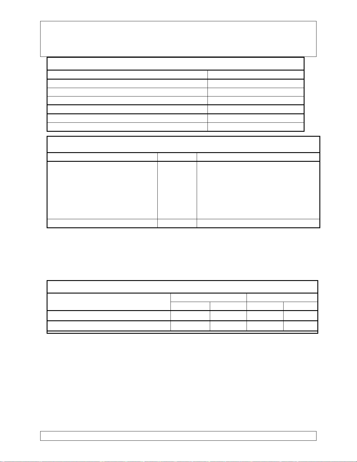
Table 2 identifies the weight of the GDL 90 System equipment. Table 3 lists the expected center
of gravity for GDL 90 System equipment as installed in various rotorcraft.
GDL 90 System ICA, Helicopter STC
Garmin AT
2345 Turner Rd SE 21 December 2005
Salem, OR 97302 Part #: 560-0255-00 Rev A
©Copyright 2005 Garmin AT All Rights Reserved Page 11 of 13
Table 2. Unit Weights
Item Weight
GDL 90 only 5.2 lbs
GDL 90 mounting tray 1.0 lbs
GDL 90 mounting tray with optional cover 1.2 lbs
Micro APM 0.1 lbs
GSL 71 only 1.67 lbs.
GSL 71 mounting tray 0.97 lbs.
Table 3. Unit Center of Gravity
Model Series & Mount Location TCDS Center of Gravity Station (inches)
AS-350 Series
Baggage Compartment
(Rack for Battery Shelf)
Upper Skin
Lower Skin
Upper Skin
Panel or Console
H9EU
152.0 (GDL 90 & tray, MicroAPM)
64.0 (GPS antenna)
89.0 (UAT bottom antenna)
184.0 (optional, UAT top antenna)
34.0 (optional, GSL 71 & tray)
Procedures and data required for wiring maintenance are described in the ‘Electrical
Connections’ section in the appropriate Installation Manuals as detailed in Section 2.1.
The electrical load analysis may need update after maintenance in accordance with AC 43.13-
1B, Chapter 11. Use the values in Table 4 for computation:
Table 4. Unit Power Loads
14 VDC 28 VDC
Input Typical Max Typical Max
GDL 90 Main Power 1.5 A 3.00 750mA 1.5
GSL 71 Main Power 200 mA 1.0A 150mA 500mA
Note: Circuits should be protected in accordance with guidelines in AC 43.13-1B, chapter 11,
section 2, paragraph 429. Power inputs should be across a minimum of all four specified
GDL 90 input pins.
2.10 Diagrams
Refer to the GDL 90 and/or GSL 71 Installation Manuals (listed under reference documentation
in paragraph 2.1 of this document) for drawings applicable to this installation.

GDL 90 System ICA, Helicopter STC
Garmin AT
2345 Turner Rd SE 21 December 2005
Salem, OR 97302 Part #: 560-0255-00 Rev A
©Copyright 2005 Garmin AT All Rights Reserved Page 12 of 13
The GPS antenna is located on top of the fuselage. See A33 or A34 Antenna Installation Guide
(listed under reference document paragraph 2.1 of this document) for antenna description.
The UAT antennas are located on top and/or bottom of the fuselage. See the UAT Antenna
Installation Guides (listed under reference document paragraph 2.1 of this document) for antenna
description.
2.11 Special Inspection Requirements
None, N/A.
2.12 Application of protective treatments
None, N/A.
2.13 Data relative to structural fasteners
None, N/A.
2.14 Special Tools
No special tools are required for system checkout. See GDL 90 or GSL 71 Installation Manuals
listed under reference documentation in paragraph 2.1 of this document.
Use of the 3/32" hex driver provided in the GSL 71 installation package (Garmin AT P/N 998-
0048) is recommended for reinstallation of the GSL 71, to prevent damage to the GSL 71 (see
Section 2.8).
Wiring maintenance may require use of the crimp & positioner/locator tools described in the
‘Special Tools Required’ section in the GDL 90 or GSL 71 Installation Manuals listed in
paragraph 2.1 of this document. No special tools are required for system checkout.
2.15 Additional Instructions for Rotorcraft Operating under FAR 121/135
1. Rotorcraft Electrical Loads: Perform rotorcraft electrical system load analysis. See
electrical load data contained in Section 2.9 of this document.
2. Methods of balancing flight controls: N/A.
3. Special Repair Methods applicable to the rotorcraft: See certificate holder’s General
Maintenance Manual for instructions.
2.16 Implementation and Record Keeping
Incorporate operational test and troubleshooting guides into Rotorcraft Maintenance manuals.
Update the wiring diagram manual and equipment list as necessary. Add each component to the
reliability program as necessary.
For operators under FAR 91, the owner/operator is responsible for ensuring the ICA is made part
of the applicable section 91.409 inspection program for their rotorcraft.

GDL 90 System ICA, Helicopter STC
Garmin AT
2345 Turner Rd SE 21 December 2005
Salem, OR 97302 Part #: 560-0255-00 Rev A
©Copyright 2005 Garmin AT All Rights Reserved Page 13 of 13
For operators under FAR 121/135, this ICA must be incorporated into the operator’s approved
maintenance program through coordination and approval with the certificate holder’s PMI/POI
as applicable.
Table of contents
Popular Toy manuals by other brands


Lionel
Lionel VISION Line700E Hudson owner's manual

Lionel
Lionel Century Club II Niagara Milk owner's manual

Super Flying Model
Super Flying Model Fournier RF-4D instruction manual

Amewi
Amewi RC Magic Traxx Glow instruction manual

LGB
LGB 22512 instruction manual

Art-Tech
Art-Tech P-51D Gunfighter instruction manual