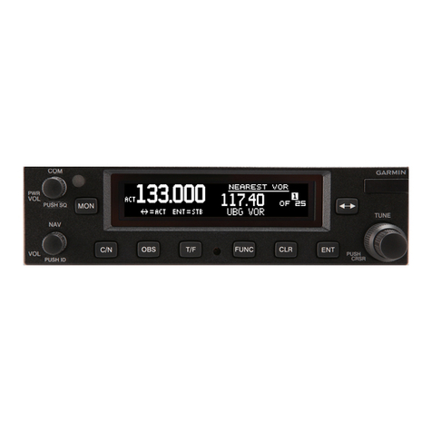
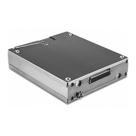
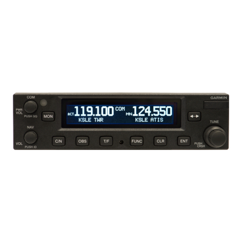
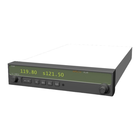
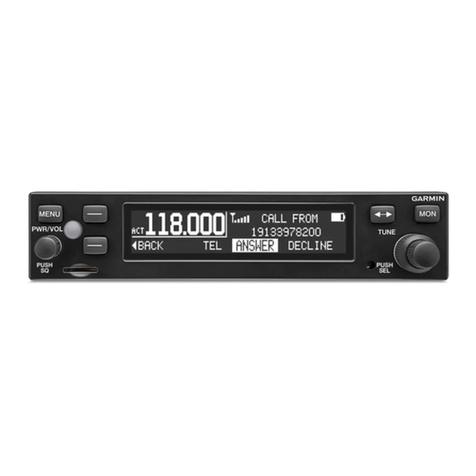
Garmin Apollo SL40 User manual

Model SL40 vHF
coMM
Transceiver
lnstallation
Manual
A
June
2008
560-0956-03
RevC GARMIN*

@2004-2008
Garmin
Ltd.
orits
subsidiaries.
All rights
reserved.
Printed
in theU.S.A.
Garmin
lnternational,
[nc.,
1200
Eastl5[" Strect,
OlatheKansas66062,U.S.A.
Tel:
91
3
1397.8200,
888/606.5482
Garmin
(Europe)
Ltd.,Liberty
House,
Bull
CopseRoad,Hounsclown
Business
Park,
Southanrpton,SO409RB,
UK,Telcphone:
+44
(0)
8708501243
GarminAT.
Inc.,2345
Tumer
Road.
S.8.,
Salem,OR97302,
U.S.A.Tel:
tJ00/581.8101
Fax:503/364.2138
CanadaTel:
800/654.3415
InternationalTel:5031391
.341|
Cage
Cocle':
OXCJ6
Visit our web pages
at ll_!p.r:,i1vry1ygi4_11111,1c_14-r1
Send
cornmcntsabout
thismanual
byemail
to:
techpubs.salem(a)garmin.com
Exccpt
as
expresslyprovided
hcrein,
no
part
ofthis
manual
maybcrcproduced,
copied,
transmittecl.dissemirtated,
clownloadccl
or
stored
inanystorage
mccliurn,
lbrany
pLlrpose
without
thc
exprcsswrittcttpennissior-r
of'Gannin.
Garntin
hcrcby
grantspcnnissiorr
todownload
a
singlecopyofthis
mattualand
of'anyrcvision
tothismanual
orrtoahard
driveor
otlter
clcctronicstoragc
mediunt
tobevicwcd
firrpcrsonal
usc,
providccl
that
suclt
electronic
or
printcd
copy
of tltismanual
orrcvision
nrustcontain
thccornplctetcxt
ofthis
copyright
noticc
and
providcdfurthcr
thatanyunauthorizccl
conrmcrcial
clistribution
of this
ntanual
or
arryrcvisiorr
heretoisstrictly
prohibitcd.
Intbrrnation
inthis
clocumcnt
issubjcct
to
changc
withoutnoticc.
Garmin
rcscrvcsthc
right
to
changc
orimprove
thcir
products
and
to
rnakc
cltangcs
inthccontcnt
oftliis
nratcrialwithout
obligation
tonotify
any
person
or
orgattization
ol'sLrch
changcs
orirnprovenrcnts.
GatntintNt,Garmin
ATrM,
and
CINSarctrademarks
ofCiarmin
Ltcl.orits
subsicliaries.
These
tradcmarksmaynot
beusedwithout
thcexprcss
pcrntission
ofGarmin.

HrsronY
oF
RnvrsroNs
Revision Date Descrintion
t2il8t96 lnitialrelease.
00A v30t97 Modified
selectivitv
value
to7kHz.
-01 3il4t97 Chance
recommendedcoaxfromRG-58
toRG-142B
-02 6126t98 New
softwareversion
-02a 9t22t99 Addednew
connector
pins
andcrimpins
tools
-03 t0nt02 Updated
shipkit informationandchangedII Morrow
toGarmrn
AT.
-03a 9/lst03 Comnanvnamechange
-03
B 4/12t40 Added
licenserequirementconrment
and
removedApollo.
-03
c6il9t08 Added
BTSOinformationancJ
updatedloso.
IrrponrANT
NorE
"The conditions
andtests
required
fbr TSOiETSOapprovalof thisarticlcareminimum
performance
standards.It is thcresponsibility
of thosedesiringto installthis
articlcon or
withinaspecifictypeor
classof aircraft
todetcnnine
thatthe
aircraftoperating
conditionsare
withirr
TSO/ETSO
standards.
Thearticle
maybc installcdonly if further
evaluatiorr
by the
user/installerdocumetrts
anacccptablc
installation
andis
approvedbythe
Adrninistrator."
Source:1'-AA
T,\O-C37d.
TSO-C38d.and TSO-C
128arul
EASA
ETSO-2C37e,
ETSO-2C38a,
untlE7'SO-2CI28.
ORUpRING
INFoRMATIoN
Toreceive
additional
copicsof this
publication,
order
part
# 560-0956-03RevC,,
SL40
VHF
COMM Instal
lationManual.

NorBs

Tahleof Contents
TnnIN OFCONTENTS
SECTTON
I - INTRODUCTION ........................
I
Asour THrsMaNUAL............. ..............
I
Apor-lo
SL40DpscRrprroN ..................
I
FEaruREs ..........I
RnculeroRv
CovplrANCE......... ..........2
UNpacruNc
rHeEeurpHaENT........... ........................
3
Pacracp
CoNrpNrs ...........
3
OrHsn
REeurnpoMRrpRre1s................ .................4
Spscral
Tools Ruqurnno. ....................4
LrceNsE
RrqurneveNTs........... ............4
SECTION
2- INSTALLATION ........5
PRe-lNsralLATroN
lNtoRtr,rarroN............. ..............
5
INsrRllarroNOvsRvrEw........... ..........
5
INsrallarton CoNsroERATroNS.. .........
5
EeurpvENr
MouNrrNc .......5
ELpcrRrcRr-CoNnscrroNs.......... .........7
ANrlNNn
INsrallarroNAND
CoNNrrclroNS............. ..............
8
Posr
INsraLLATroNCHrrcrcour ..........l2
SECT|ON
3- SPECTFTCATIONS............... .....
ls
ELecrRrce1................ ......
15
PHysrcal.. .......
l-5
ENvrRoNvtrNTAL....... ........
15
REcsrvER
PERponvaNCts........... .........16
TRaNsvrrruRPsnnoRMANCrl .............
16
INrEncov
PeRronnaRNCE........... ........l7
CoNrRor
lNpurs ...............l7
ANTSNNR
ReeurnenasNrs........... ........
11
SeRral
INrEnracE .............17
REanCoNNpcroRPrNour ..................
18
SECTION
4- LIMITATIONS.. .......
19
INsraLLRrroN
........... ........
19
OpEnatrctNAL............. ....,..
19
APPENDIXA-TROUBLESHOOTING.............. ..............2r
CoNracrtNG
THEFacroRv
roR
AssrsrANCts........
SL40
Instal
lationManual
2l

Tableof Contents
APPENDIXB - PERIODIC MAINTENANCE ..................23
EqutllalNr
Cat-rsRanoN............. .......23
ClEaNrNc
rHEFRoNTPansl....... ........23
APPENDIXC - ENVIRONMENTAL QUALIFICATIONS.. .............25
APPENDIXE - SERIAL INTERI.'ACE
SPECIFICATIONS............... ...............,27
RS-232lNpurs ...........27
RS-232Ourpurs ...............29
Lrsr oFTABLES
TaBr-EI Pncrncu
CclNreNts ...............3
TRSLE
2 CoNNt'c'roR
PtNor,r'r'
............... ................
l8
TaslE3 TnouBr-ESHoorrNG
Guroe....... ...............21
LTsToF ILLUSTRATIoNS
Frcuns
I SL40
FRorrPRNgI ...............2
FrcuRt'2 MouN'rrNcFRanasAssgn,tBr.y .................6
FrcuRs3 CnULERourrNc... ..................6
FtcuRr'4 Coax
CoNNr'c.roRAssEnrBr-y.............. ..........-..........9
FrcuRr,5SL40SraNoRloNr'WrRrNc;Drncnav .......
...........10
Ftcune6 SL40
Typrc'nr-
AuoroPnNel
CoNNrrcrrr)NS............ .................I
l
FrcuRt,7 Unrr
DrHat:NsroNS
................ .................
I
6
SL40InstallationManual

Introduction
SncuoN
I -IxrnoDUCTroN
Asour TrtrsMl.Nu.q.r
Thismanual
describestheinstallation
of theSL40
Comm.
It is intended
for useby persons
certifiedby the
FederalAviationAdministration
(FAA) to install
aircraftnavigationdevices.
It includesinstallation
andcheckoutprocedures
for theSL40unit to standardsdescribedin
FAA advisorycircular
AC 20-618.
Provides
an
introduction
totheSL40unit.TSO
certificationinformationis
also
included
inthis
section.
|SectilZ Includes
installation
and
checkout
procedures.
F."tt"e Includes
completespecifications.
|Sectt"rr4l Includes
limitations
fbr
thc
equipmentand
installation.
Epp.trdtJl Includestroubleshooting
infortnation
lAppendix
Bl Includes
periodic
maintcnancercquiremcnts.
lAppendix
C
I lncludes
theenvironmental
qualification
form.
Epp.ndtTl Includesserial
dataspecifications.
SL4O
DNSCRTpTIoN
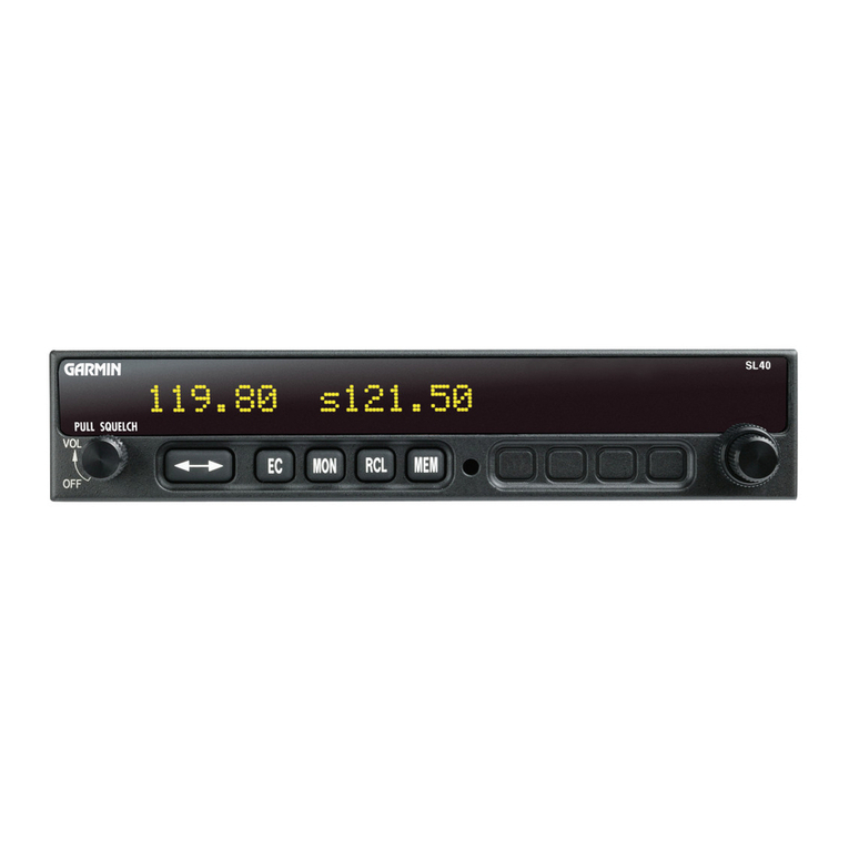
TheSL40isa 760chanr.relVHF Cornm
transceiver.lt isonemember
of the
slimline
series,
which
includes
the
SL40Comm,
the
SL50GPS,and
the
SL60
GPS/Comm.
Fn,q,ruRns
Thefbatures
of the
SL40Comminclude:
o 760channels
o Frequencyrange
of 118.000
to 136.975MH2
o Active
and
standby
frequency
display
o l6 characterhigh-intensity
alphanumeric
LED display
o Automatic
display
intensity
o Back-lit
buttons
o Transmit
statusindicator
. Frequency
memoryandrecall
functions
SL40InstallationManual

Introduction
a
a
a
a
a
a
a
a
fiorn remote
source
eight
lastr:sed
eightuserstored
Weather
channels
Frequencymonitorfunction
Built-ininlcrconrfunction
Stucknrictime-out
Twomicrophorrcinputs
Irrternal
non-volatile
mcmory
- no
battery
required
Full
rangeinput
supply
voltage
l2 wattaudioanrplif-ier
Transmit Standby
Annunciator Symbol Standby Large,
Outer Small,Inner
Frequency Knob Knob
Active
Frequency
Photocell l|4ONRCL ||llE|l|l
Power/Volume/Squelch Store
Memory
Flip/Flop Emergency Frequency
Frequency Channel Monitor
Figure1 SL40
FrontPanel
RnculnroRY Conn
PLTANCE
Thc SL40isdesisncdand
testcdto f( ETSOs
The
SL40complieswiththe
FCC
requirements
specified
in:
CFR
47,Part
87,
Aviation
Services.
SubpartD,Technical
Requirelnents
CFR47,
Part
15,RadioFrequency
Devices,
Subpart
B,UnintentionalRadiators
The
SL40softwareisdesigned
andtested
toRTCA/DO-I
78B/ED128,levelC.
ll
-.4 . t.t L ! J
=. IC. Iu.-ll:].l
TS II umecr Ine Ioltowtn a
Description TSO ETSO
Transmit TSO-C37d ETSO-2C37e
Receive TSO-C38d ETSO-2C38e
Unintentional
Transmission
(stuck
mic) TSO-Cr28 ETSO-2CI28
SL40
InstallationManual

Introduction
The SL40 meetsthe additionalstandardsas detailed
in the Declaration
of Conformity
includedon
page
31.
Note: Unauthorized
changesor modificationsto the SL40 may void the compliance
to
required
regulatoryagenciesand
authorizationforcontinued
equipmentusage.
UN{pncKrNG
THEEqurnnrENT
Carefully
unpacktheequipment.Visuallyinspect
thepackage
contents
for anyevidenceof
shipping
damage.Retainall shipping
containers
and
packaging
materialin casereshipment
is
necessary.
Pncx,q.cE
CoNTENTS
As shipped
fiom theGarmin
AT, Inc. factory,the SL40 package
includesmostnecessary
items
for installationotherthansupplies
normally
availableattheinstallationshop,such
as
wire andcableties,
andrequiredinput
andoutpnt
equipment.
The itcmsincluded
in the
package
are
listed
inTablel.
Table
I Package
Contents
ParI
#Description Qtv
Cornrn
unit
430-6040-2xx SL40
Cornrrr'l-ransceiver I
SL40
InstallrrtionKit. I'art# 424-2006-2xx
162-0100
or
162-1515 |
5
pin
dsubconnector
shell
I62-
I008 Right anf.Ile
coax Dlr,rs
202-000I Cable
tie 2
204-2t00 Shoulderbushins 2
22t-0400 4-40x l/4 SS
nanhcadI'hillios
rnachincscrewwith lock
washer ,1
224-0404 4-10x ll4 SSflatheadPhillinsmachinescrew b
245-0022 or'
245-0021 Crirnpcontactfirr
dsub,
20Io24
awg
wire l-5
3r0-5181-01 Mounlinsfi'anrc
310-51u7-01 Connectorrnountins
olate
998-0048 3/32hexdriver
204-0031 EdgeRromrlet 6"
SL40
Manr.ralKit,Part# >64-0064-2xx
560-0954-xx SL.l0
User's
rnanual
560-0956-xx SL40
lnstallation
manual
SL40Instal
lationManual

Introduction
OrnEn RnqurnED
MATERTALS
The SL40 is intended
fbr usewith standard
aviationaccessories.
The followins itemsare
requiredfor
the
installation:
. commantenna
withcables
o amicrophonc
. aspeakerorheadphone
Theseitcmsmaybe installed
dedicated
to theSL40cornm
or by connections
to anaudio
panel.
SpEcrnl
Toor-s
REqlrInrn
Crimp Tool
A crimptoolmcetingMIL spccification
M2252011-01
anda positioncr/locater
arerequiredto
ensurcconsistcnt,
rcliablc
crimpcontact
connectiorrs
fbrthereard-subconncctors.Thesc
tools
arcavailablefrom:
For
pirrpln
245-0022
Astro'['ool
Corp.
21615SWl'V Ilighway
Beavcrton,OR
97006
Crimp
tool:
Positioncr:
Phonc
(503)
642-9853
Fax (503)
591-7766
Astro
Toolpart
#6
|
5701t
AstroT'ool
part
#616356
For
pinpln245-0027
ITTClannon Phonc
(7
14\261
-5300
Iu5I E.DeereAvc. Fax (7
|4\575-8324
SantaAna,CA 92705-6500
Irrsertion
tool: ITT
part
# 274-7006-000
(Dcsc.
CItsT-20HD)
Regularcluty
Crimptool: lT'l'part
#995-0001-5ti5
(Desc.
M22520/l-01
)
Rcgular
dutyLocatortool: ITTpart
#995-000l-244
(Dcsc.
TH25)
HeavydutyCrimp
tool: ITTpart
#995-0001-5t34
(Desc.
M2252012-01)
HeavydutyLocator
tool: ITTpart
#995-000l-604
(De
sc.
M2252012-08)
LtcExspRn,eurnEMENTS
An aircraftradiostationlicense
isrequired
fbroperationof thetransmitter
onceinstalledin
theaircrati.An applicationnrust
besubnrittcd
on FCCFonn404,which
maybeobtained
fromthe
FCCin Washington,DC, or any
of itsficld ofl-iccs.Procedures
for applicationsare
inCFR
47,Part
87,Aviation
Seruices,
SubpartB,Applications
andLicenses.For
aircraftnot
registeredinthe
UnitedStates,
please
follow
yourlocal
procedures.
SL40 Instal
lation Manttal

Installation
SncrroN
2
-IxsreLLATroN
This section
describes
the installation
of the SL40 including
mounting,
wirin-e,
and
connections.
A post
installationcheck-out
procedure
is
includedat
theendofthis
section.
PnE.IxSTALLATION INFORMATION
Always
follow
good
avionics
installationpractices
per
FAAAdvisoryCirculars
(AC)
43.13-
IA, 43.13-2A,and
AC 20-67B,orlaterFAA approvcd
revisions
ofthesedocuntents.
Follow
theinstallation
procedure
inthis
section
as
it is
presented
lbrasuccessful
installation.
Readtheentircscction
befbre
beginning
the
procedurc.
Perform
the
post
installation
check-
outbefore
closing
the
work
area
in
case
problemsoccur.
INsrulATIoN OvoRvIpw
A successful
installationshould start with careful planning irrcludingdctcrrnination
of
mounting locationfor the SL40, antcllta nrounting,
connc'ctiorrs
to microphones,speakers,
and
headphones,cable
routing,and
otlicrrequired
mociiflcations.Once
thcmounting
locatiotr
hasbecn
dctcrminecl,
prepare
thcmounting
framcfbr installation.lt maybeeasier
tocomplete
the wiring harncss
and attachthc conncctors
to the ntcrurrting{i'arnebcfbre installingthe
mounting
fiamc.
lxsrnllATroN CoxstnERATIoNS
MouNrlNc CoNsl
oERATIoNS
TheSL40
isdesigned
tomountintheavionics
stack
irrthcaircralt
instrumcnt
pancl
within
easy
vicw andreachof thcpilot.
Thc stanclard
packageincludcs
a nrountirtg
fianrcfbr ease
of
mounting,
conncctiorrs,
andscrvicc
of tltc
unit.Allow an additionalonc incltclcarance
to tlte
rearof themounting fiame fbr ct'urncctors
andcablcs.
For typical installertrons,
thc SL40 doesnot requirecxternalcooling. Whcrr rnounting
thc
SL40,
leave
aclear:.rnccof l/tl to ll4 inch
between
aviotrics
toallow fbr circulation.
MrNrnaunr
Svsrsnl
CoNnrcuRATToN
TheSL40
requires
connectionsto thc
fbllowing cquipnrcnt
asa mitrimunt:
o powcrinput
. speakeror hcadphoncoutput
. microplronc
iltpul
. anantcnrla
EgurruENr
MouNrtxc
Oncethe cableassemblies
lrave
beenmade,
attach
the 15 pin dsuband coaxialcable
connectors
to the rearconnectormountirrg
plate
andthe mounting
frame
asillustrated
in
Figure
2 and
Figure3. Routcthe wiring bundle
as appropriate.
The rearconnector
plate
should
beattached
to themountingframe
before
installing
theframe
in theinstrument
panel.
Tlierear
connector
plate
canbe usedto tiedownthe
cableassemblies.Connect
theshield
groundsdirectlytothe
connector
rnounting
plate.
SL40InstulIation
ManuaI

Installation
.r.- MovnLtnqFrame
444
xlA Sccan
(4xI
Figure2 Mounting
FrameAssembly
4-4O x 3/6 Flatf'ead Screw(6x)
s ConnecLor Mounttn4
6racket
ur Edqe Guard
|
5-?n D-5ub
RA Coax
?luq Shoulder'
bvshtnq
Edqe Gvard
/
Coax
ConnectorE
Eo Float Freely
'Cable Te
/
ConnecL Shtelds /'
to Frame'
'fhe >held ptqtatb musl
beless Lhan1".25tnches,
lhe shorter the beLter.
Figure3 CableRouting
Oncethe cableassemblies
arecomplete
andthe comectorsareattached
to the moullting
frame,
installthe
mountingfiame
assembly
in theinstrument
panel.
Be
sure
touselowprofile
headscrewssothe
unitwill slide
in and
outfreely.
Attach
thefront
of the
mountingframeto
theinstrumentpanel.
Usesupport
brackets
toattachtherearof theframe
totheaircraft.
-\
\
s \.\-
SL40Installation Munual

Installation
head
screws
so
the
unitwill slide
inandoutfreely.
Attach
the
front
of themounting
frame
to
theinstrumentpanel.
Use
support
brackets
toattach
the
rearof theframe
totheaircraft.
To install
theunit
in thc
mounting
frame,
makesurc
the
canrlock
is
rotatc6
sothe
rear
part
is
up, then
slidethe unit into thc frame
andtighten
with the 3132hextool.The unit will be
pulled
into
thefranre
bythe
canr
lock
andtlie
connectclrs
will fullyengage.
To remove
thcunit from the
ntounting
frame,
use
thehextool and
turnthetoolCCW. The
ullitwill bepushed
out
ofthe
fianre
bythe
camlock
assembly.
Nospecial
cxtraction
tools
are
rcquired.
EIpcTnICAL CoxuEcTIoNS
The
SL40
installation
kitincludcs
a l5 pin
dsub
shelland
crinrp
contacts.
Thccrimp
contacts
are
specified
lbr 20 t<t24 AWG wire. Make
thc crirnp
connections
with a crimp
tool as
specitied
inthe
Special
Tools
Required
section
on
page
4.All wires
should
lre
20
to24
AWG
unlessotherwise
spccificd.
A wiring
diagram
isincludcd
asFigure
5.
Pownn
The
SI-40
isinternally
fuscd
at7amps.
A scparatc
5 arnp
(maximum)
circuit
brcaker
orfuse
should
be installed
for downlirre
ovcrload
or shortcircuit protection.
Make t6c powcr
conncctions
tothe
SL40
using
20
awg
wire.
Note: Circuils.tlrould
lta
ytntlaclael
in ucc:oreluncev,ith
guidalincs
in1lC 43.t-i-lA, chaptt:r
II.
section2,
parugruph429.
SpeaxnR AND
HEADpuoNE
Out'pu.r's
Clonnect
thc
spcaker
ancl
headphones
tothe
outputpins
cln
thcrcar
copncctor.
MTcRopHONE
lNpurs
Microphone
input
contlcctions
shor-rld
be
nradc
using
atwistecl
pair
shicldccl
cable.
Attach
the
signal
ground
to thenlicground
pin
onthcrcar
conncctor
and
connect
thc
shield
tothe
rear
cclnnector
plate.
Tn,qNsN.{rr
KEylxpur
Thc TxKcy input on the rcar connector must be pulled low to grould to cnablc the
transmittcr.
This input sltould
be conncctcd
to a nricrophouc
or yokc rnountccl
momentary
push
button
switch.
IxrrRcoM SEI-ECToR
SwtrcH
The
SL40
includes
anintercom
function
that
can
beenabled
byan
external
control
switch.
This
isan
optional
connection.
When
making
connection
fbrthe
intercom
selection,
connect
the
intercom
selection
input
toa
remote
moutttecl
normally
open
switclt.
A niomentary
toggle
or alternate
action
switch
can
be
used.
Conltect
theother
terminal
of theswitch
to ground.
Theintercom
function
is enabled
when
theinput
ispulled
low
to
ground.
SL40Installation
Manual

Installation
SBRIll IxrrRRecn
The SL40 includes
an RS232serial
port,which can be usedfor inputtrng
frequencyand
functioncontrolcommandsand
outpurting
transceiverstatus.Thisisanoptionalconnection.
Whenrnakingserial
conrtectionstotheSL40,Lrse
ashicldedthrccconductorcable.Makethe
RxD,TxD,and
grouncl
connections
onthe
l5 pin
conncctor.
Connecttheshieldtothe
rear
of
themounting
fiameon
theconnector
plate.
The SL40canbc connected
to the ItS-232
scrial
dataoutputson the200lGPS
(requires
softwareversion
5.1orlatcr),
thc
SL50,SL60,
GX50,
GX5-5,
GX60,orthe360Map/GPS
for
receivingrertrotefiequcncy
infbnnation
liom theGPS
navigation
databasc.
Rcf-er
to thc
installationmanualslbrthosc
unitsfilr
conncctionsandscrial
dataoutput
selcctious.
Corupleteserial
intcrface
spccifications
are
includcclinAppendixB.
ANrn,NxAINSTALLATToN
AND
CoNNocrroNs
The SL40 requires a standard 50Q vcrtically polarized antcnna. Follorv thc antcnna
manufactut'er'si
nsta
l
lationirtstructions
tbr nrounti
ngthcantcrrna.
Thc antcttnashcluldbelnountcd
on a mctal
surfacc
or a groundplanc
r,vith
a minimurn
arca
of
It3
x lli inches.
The antcnna
shouldbc rnountcd
a minirnunr
of'24 inchcs
away fiom GPS
antcnnas.
The cottrm
antcttnashould
alsobc mountcd
as f'ar
apart
as practical
fiorn the L,L'f antenna,
prcf-erably
onc olr top and tlrc otlrcr orrthc bottornof tlrc aircraft flselagc. Solne ELTs have
exhibitcdrc-radiationproblcnrsgcncrating
harrnonics
that nray interf-erc
with CiPSsignals.
This can l-ritppcrr
wltcn thc conrnr(SL40 or any othcr cclnrnr)is trausnritting
orr certain
fiequencics
such as l2l.l,5 or l2l.l75 MlJz, which nray causcthc trLT output circuit tcr
oscillatefiom the
signalcontingin on thcELT antcnna
coax.
The antcnna
coax cableshouldbc madc ot'I{Ci-142B or a comparable
cluality
50f) coax.
Asscmblyirtstructions
fbr thcrear
coa\ conncctor
areincludcdin FigLrre4.
SL40In.;lallatiun
Mantral

In,stallation
ClampNut
Step
l. -Slideclampnut
over
coax.
-Strip
coax
asillustratcd.
-
Cuttwol/4"
slits
in
jacket
180
degrccs
apart.
Step
2. BraidClamp \
r i/mnr I
Iil\\\\ifl n
b lll\\j
1l''- Slidc
braid
clampovcrcnd
of coaxand
undcr
the
braid.
Step
3. cap -\ \=--
E: - Inscrt
coax
with braidclamp
into
conncctorandtightcnclarnp
nut
sccurcly.
- Soldcr
thc
ccntcrconductor
of thc
coax
to thccontactas
illustrated.
-Attachthccap
and
sccurctightly.
Assembly
instructionsfor right anglecon l
nectorpart #162-l00tl
Figure4 CoaxConnectorAssembly
SL40
Installation
Monual

Installation
Power
*
Ground
Reserved
Speaker
Headphone
AudioGround
sL40 MicI
COM Mic2
Mic Ground
TxKey
Intercom
RxD
Serial Ground
I
9
2
6
t4
13
8
l5
7
4
t2
3
l0
ll
5amF
fuse
or-hreaker
.{\'-' \_/ TAvionics
Power
HeadphoneJack
HeadphoneJack
L-l MicJack
f
-ll Mic Jack
-_r-'.
ooor
I
!';.-fl +
Yoke mount
transmit buttons
.,.-..l
otr- J
Intercom
Selector
Switch
(optional)
Notes:
RS-232Serial
lnterface
Coax ComAntenna
l. Connectcable
shieldsto therearof themounting frarne,
with pigtails < 1.25inches.
2.Useshieldedcablefor themicrophoneconnections.
3.Useshieldedcablefor theRS-232serialinterfaceconnections.
4. Connect
shieldsto chassis
groundatboth endsofcables.
Figure5 SL40Standalone
Wiring Diagram
IO SL40lnstallationManuol

Installation
[--; Ground
Reserved
Speaker
Headphone
Audio Ground
sL40 MicI
COM Mic2
Mic Ground
TxKey
Intercom
TxD
RxD
Serial Ground
13
8
l5
4
12
J
l0
l1
ComAudioIn
Audio Ground
Com
MicAudio
Mic Ground
ComMic Key
Cbssis Ground
I .Connectcableshieldsto the rearof themounting frame, witb pigtails < 1.25inches.
2. Use shielded cable for the microphone connections.
3. Use shieldedcablefor the RS-232 serialinterface connections.
4. Connectshieldsto chassis
ground atboth endsofcables.
5. The audio ground and mic ground connections may use a common point at the audio panel.
Figure6 SL40Typical
AudioPanel
Connections
SL40Installation
Manual 1I

Installation
PosrIrusrarlATloN
Curcxour
Oncetheunitis installed,
complete
the
checkout
procedure
toverifyproper
operation.
Refer
to
theUser'sGuidefor
operatirrginstructions.
Mounting/ Wiring
Check
Verify thatall cablesare
properly
sccured
andshields
areconnectedto the rearof thc
mounting
frame.
Chcck tlremovement
of thc aircraficontrolsto verify that thereis no
interf-erence.
Receivcr
/ Transnritter
Operation
Tunc the unit to a localficqucncy
and verily thc receivcr
output
produces
a clear
and
understandable
audiooutput.
Verify
the
transrnittcr
bycontacting
another
station
and
getting
a
reportol-
rcliablc
ctlrnrtturricatiorrs.
Antenna
Check
TheantennaVSWR catrbc checked
usingan inlinewattnretcrin thcantenrracoaxusing
frequencics
near
both
cndsoftheband.The
VSWR
should
be
<2:1,
andisnottoexcced
3:1.
A VSWRof 2:l will causea dropin outputpower
of approxirnately
l2o/o.and3:l causes
approxinrately
a26'%drop.
Interfercncc
Check
Check
theSL40
while
operatingthcothcr
avionicsand
elcotrical
systemson thcaircraftto
vcrify thatno significantintcrt'ercttce
cxists,
and
thattlre
SL40
does
notcause
significant
interl'erencc
with other
systcms.Pcrlbrmance
shouldbecheckedusing
low,high,andnrid
band
fiequencics.Repcatduringthe flight testfbr equipnicnt
thatis not checked
on the
ground.
Sidctone
Levcl
Adjustmcnt
Thesidctonc
volumcwas
presct
at thefactoryto whatshouldbeanacceptablclcvcl.The
levelcanbcacljustcdintheSystcmFunctions
modc.
Toadjust
thc
sidetonelevcl:
l. Press
andhold the MttN br-rttonfor about
two seconds.
This will accessthe System
Functionsmodc.
2. Rotatc
the
t-Rncrr
knobtodisplaythe
SroeroNBLvt.
page.
3. RotatctheSn,lnt.l
knotr
to change
thclcvel
nunrbcr.Therangc
of thcnumber
is000to
25-5,
with l2tSprodLrcing
onchalf
of fullratcdoutput.
A settingof 000slavesthelevel
to
theVolurne
knob.
4. Prcss
any
kcytoexitthcSetupFunctions
modc.
5. Selcct
an appropriatc
fieqLrency,key thc transmitter,
andtalk into themicrophonc
to
chcck
the
level.
ReceiverSquelch
Adjustment
Adjustmentstothereceiversquelchlevel
may
be
pertbnned
byusingthe
RcvnSgalcn
page
inthe
TestMode.Valuesmaybeadjusted
betrveen25and
100.
l. Pressandhold
the
<>andRcl keys
while
switching
theunit
on.
2. Turn
thc
LeRcrknobtotheRcvn
SqucH page.
3. Pressthe<+ keytostartselection
(the
nurnberwill flash).
4. TurntheSvall knobtochange
the
value.
PressMEv tostorethe
value.
5. TurntheunitofftoexittheTestMode.
l2 SL40InstalIationManual

Installation
Mic LevelAdjustment
Thoseunitswithaudio
board
pln415-7008-01,
orlater,
havethe
abilitytontakeadjustments
to microphone
sensitivityby using
theMtc I LEvul and
Mrc 2 Luvut pages
in theTest
Mode.
l. Press
and
hold
the
<>andRcl keys
while
switchingtheunit
on.
2. TurntheLnncsknobtothe
Mrc I Lsvur-andMrc:
2Luvutpages.
3. Press
thee keyto
startsclection(the
numberwill t)ash).
4. Turn
theSnlnll knob
to
change
thevalue.PressMel,t
tostorethe
value.
-5.Turn
theunit
ofTtoexittheTest
Mocle.
Display
Test
It is possible
to perform
a sinrplc
testto observcall scgnrcnts
of thcdisplayfor a clr,rick
checkout
ofthc
displayfunctions.
l. Press
and
hold
thc<+andRc:r-
kcys
whilc
switclringthcunit
on.
2. Turn
thc
Lnnc;s
knob
tothcDISPLAY
T'ESTpagc.
3. Press
Mt'nl
to pcrform
thc
test.
A sericsof "#" syntbolswill advancc
acrossthe
display
tcstirrg
eachLBD.
4. Turnthcunit
offto
exittheTcst
Moclc.
Nlic
Squclch
Adjustrncnts
to thcsquclclrlcvcls
firr
Micl andMic2are
availablcin thc
System
Functions
modc.To
adjLrst
theMicropltonc
Scluelchlcvcl:
l. Prcssandhold thc Mtllt button
tbr irbout
two seconcls.
This will access
tlrcSystenr
l-
unctionsntode.
2. Rotate
thcLARGtT
knobto
display
thcMrcI oHMrc'2
Ser.cru
pagcs.
3. RotatethcSptnll knobto change
thclevelnurnbcr.
Thcrangc
of tlre
numbcris 000
to
127.
4. Press
any
kcy
toexit
thcSctupFunctions
modc.
-5. Sclcctan appropr-iatc
l}equerrcy,
kcy thetransrnittcr,
anci
talk intothe microphone
to
chcckthelevel.
Transmit
Mic
Thc Transmit
Microphonepage
allowsyou to controlwliich microphone
is permitted
to
trarrslnit.
Yountay
chooscMic I
.2.or both.
To
adjusttltcJ'ransnrit
Mic
control:
l. Press
andhold thc Motl button
fbr abouttwo seconds.
This will acccss
thc Svstcn-r
Functions
nrodc
2. Rotate
thc
laRc;c
knob
to
display
thcTrr.RNsrvlrl
Mrcpagc.
3. Rotate
theSHanll
knobto
sclcct
MICI
,MIC2,
or
MIC
l+MlC2.
4. Prcssanykey
toexit
the
Setup
Functions
modc.
5. Sclcct
an appropriatc
fiequency,
key thetransmitter.
and
talk intotlremicrophones
to
checkfbrthe
intcndedoperation.
FlightTcst
Check
A fltghttestis reconrmended
asa final installation
verification.
Theperfbrmance
may be
verifiedby contacting
a ground
station
at a rangeof at least
50 nm whilemaintaining
an
appropriatealtitude
and
overallnornral
flightattitudes.Perfbrntance
should
becheckedusing
lorv,
high,
and
midbandfrequencies.
SL40InstallutionMunual I5

Installation
NorEs
t, SL40
Install
ationManual
Other manuals for Apollo SL40
3
Other Garmin Transceiver manuals

Garmin
Garmin AIS 600 Reference guide

Garmin
Garmin GNC 250 Operating instructions

Garmin
Garmin echomap 40 series Manual

Garmin
Garmin GDR 66 User manual

Garmin
Garmin GNC400 Manual

Garmin
Garmin GTR 200 Manual

Garmin
Garmin GDL 88 Manual

Garmin
Garmin Apollo SL40 User manual

Garmin
Garmin GDL 82 User manual

Garmin
Garmin AIS 800 User manual

Garmin
Garmin GTR 225 User manual

Garmin
Garmin G60 User manual

Garmin
Garmin GDL 82 User manual

Garmin
Garmin GTR 200 User manual

Garmin
Garmin GTR 225 User manual

Garmin
Garmin GTR 200 User manual

Garmin
Garmin GDL 88H Technical specifications

Garmin
Garmin AIS 800 User manual

Garmin
Garmin GNC 255A Manual
Garmin
Garmin GTR 225 Manual