Garrard MRM101 Operating and installation instructions

Serviceinformationfor
ModelMRMIOI
MusicRecoveryModule
Garrard
MusicRecoveryModuie
Index
Introduction
Connections
Operation
Sparepartslist
Circuitdiagram
Dismantling
Testprocedures
page
2
2
3
4
7
12
12
DetailsofauthorisedGarrardservicecentresareavailableonrequest.

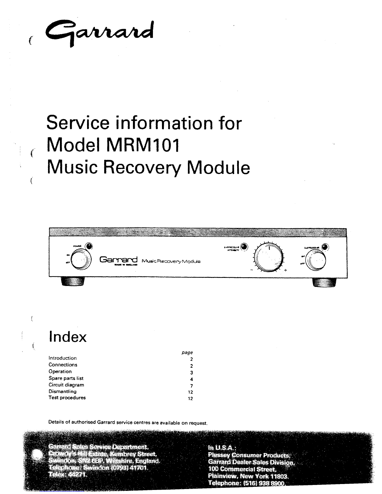
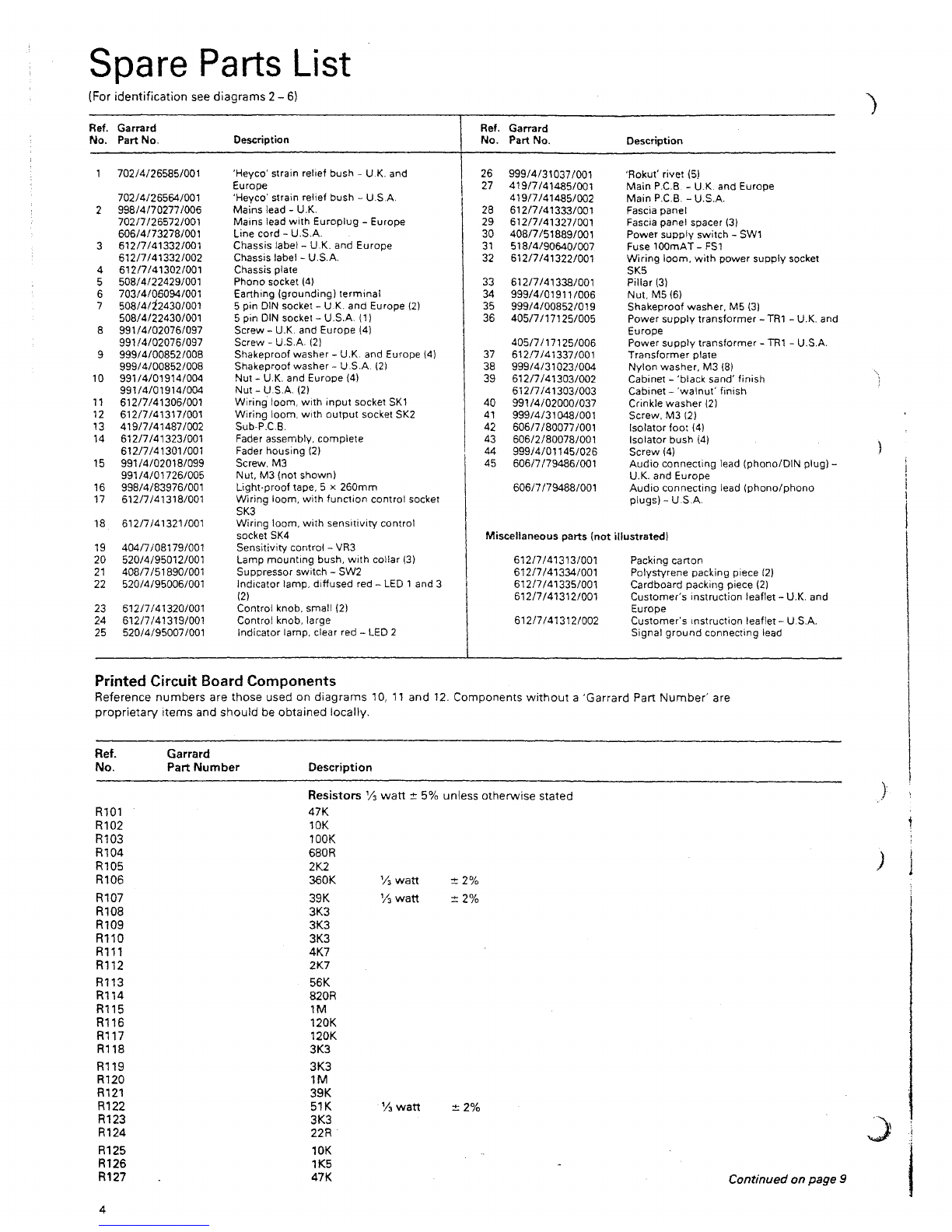
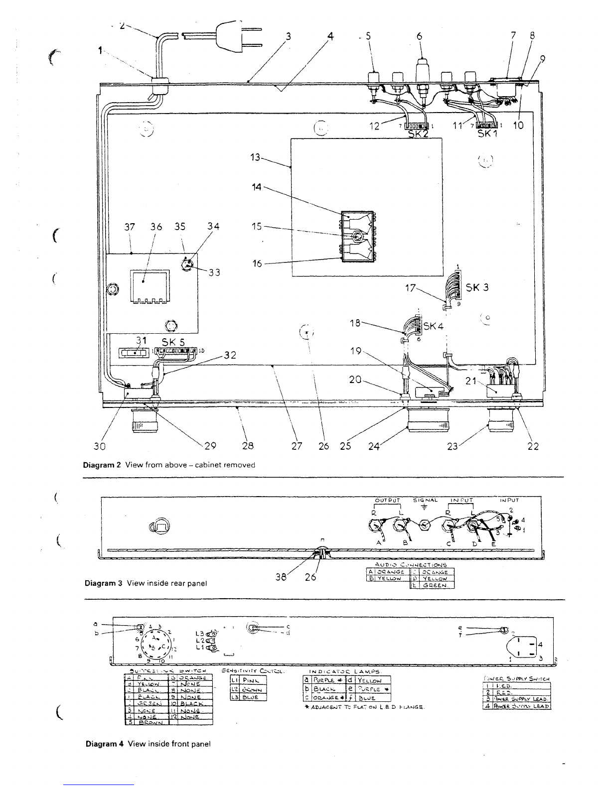
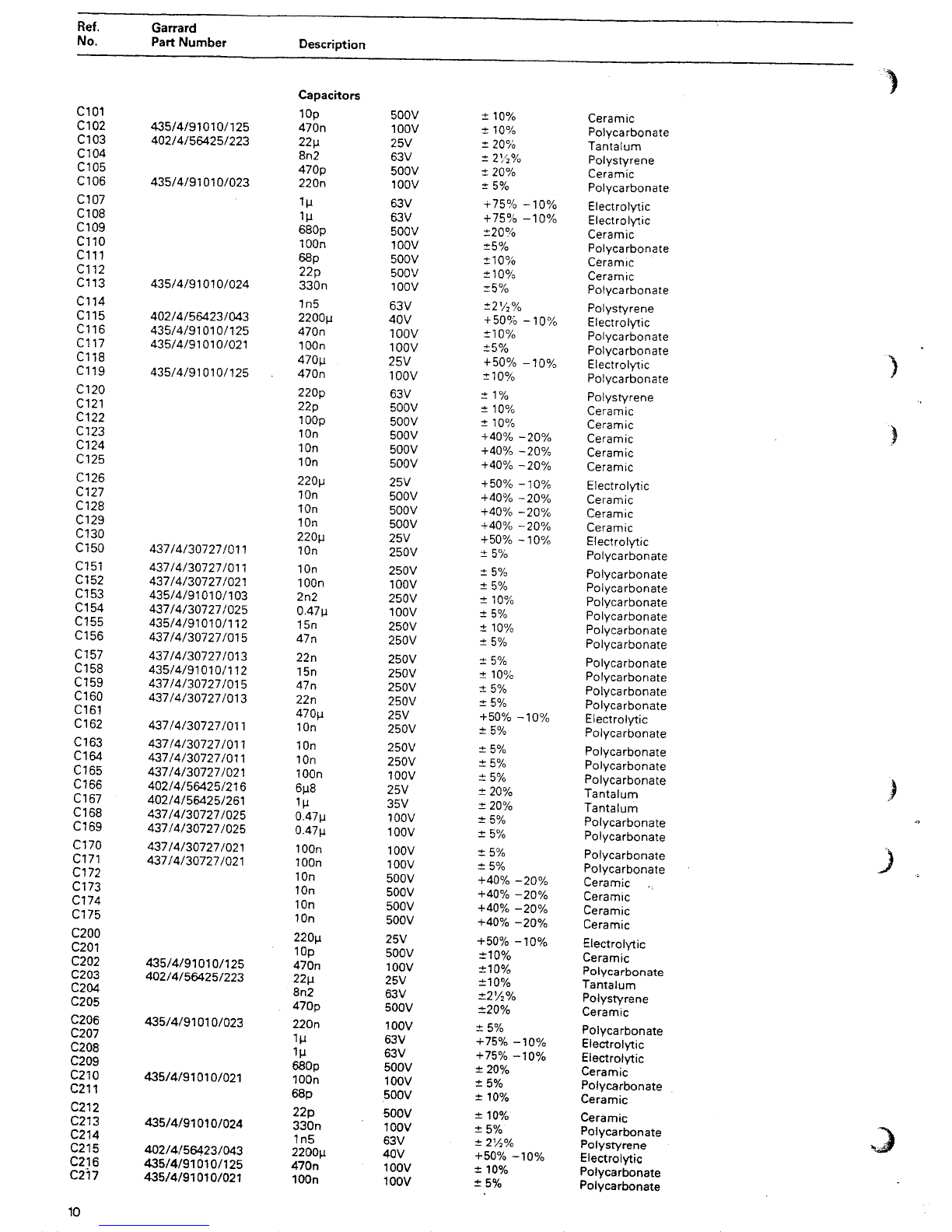
ModelMRMIOIMusicRecoveryModule
Introduction
TheMusicRecoveryModule(referredtoasMRM)isdesigned
toremovetheobjectionablenoisesheardwhenaphono
pickupmeets
a
scratchontherecordbeingplayed.
TheMRMisnotintendedtoremoveallnoisesassociatedwith
old,
wornorgenerallydirtyrecords.Sincethesenoisesoccur
inanalmostcontinuousmanner,theirdetectioncouldleadto
theremovalof
a
substantialproportionoftheoriginal
recording.
TheMRMcontains
a
highqualitystereopre-amplifierwith
magneticphonoinputs.ThisallowstheMRMtobesimplyand
directlyconnectedtotheamplifier'auxiliary'or'tuner'inputs.
Thescratchdetectioncircuitrecognisesthewholewaveformof
thescratchanddistinguishesitfromthepeaksoftherecorded
music.Inordertoallowthescratchdetectioncircuitsufficient
timetomakethedecisiontoremovethescratch,thechannels
areindividuallydelayedby
a
fewmiUi-secondswithoutlimiting
theaudiofrequencyrange.
Afterrecognisingthescratch,aspeciallydesignednetwork
isolatesthesignalforsufficienttimeforthescratchnoiseto
passoutofthedelayline.
Patentsappliedfor.
WARNING:Topreventfireorshockhazard,donotexposethis
appliancetorainormoisture.
Specifications
Input
Suitableforpickupcartridgeshavinganoutputof0.7to
2mV7cm/sec.
Inputimpedance
47kohm.
Frequencyresponse
±1.5dB
2OH2
to20kHz(includingequalisationnetworkfor
magneticcartridges).
Dynamicrange
Directmode:greaterthan100dB.
Viasuppressor:greaterthan80dB(typically85dB).
(Unweighted20Hzto20kHzref.to1kHzmaximumoutput.)
Distortion
At1kHzatnominaloutput:
Directmode:Typicallylessthan
0.01
%
T.H.D.
Viasuppressor:Typicallylessthan
0.1
%
T.H.D.
Channelbalance
Betterthan2dBat1kHz.
Nominaloutput
300mVRMS.
Output
For
1%
T.H.D.at1kHz:
Suppressor'in'2.5Vrms.
Suppressor'out'8Vrms.
Outputimpedance
3.3kohm.
Ratedloadimpedance
Greaterthan10kohm(shortcircuitprotected).
Powersupply
120V
AC,
50/60HZ7VA,or220/240V,AC50/60Hz7VA.
Dimensions
378mmx 298mmx 71mm(Wx D x H).
Shippingweight
3.7kg
(8.161b).
Garrard'spolicyisoneofcontinueddevelopmentand
thereforetheCompanyreservestherighttoalterspecifications
withoutnotice.
ForServiceandEnquiries:
GarrardEngineeringLimited,
SalesServiceDepartment,
KembreyStreet,
Swindon,
WiltshireSN26BP.
Telephone:Swindon(0793)41701
Or,in
U.S.A.:
PlesseyConsumerProducts,
GarrardDealerSalesDivision,
100CommercialStreet,
Plainview,NewYork11803.
Telephone:(516)938-8900
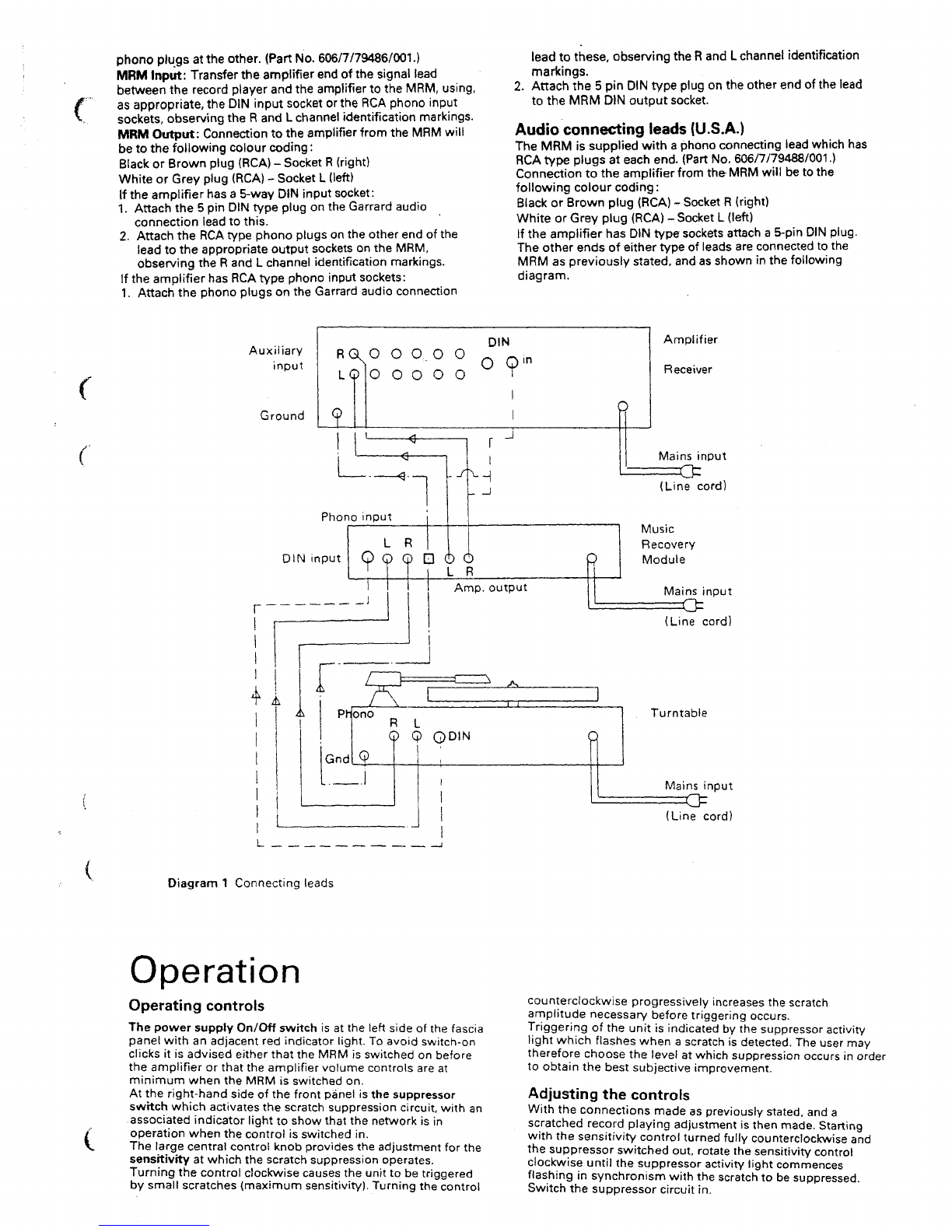
Connections
Connectingtothepowersupply
Thepowersupplyleadentersattherighthandsideoftherear
panel.
Important: Beforeconnectingtothepowersupplyensureby
thevoltageinstructionlabelonthebackpanelthattheMRMis
suitableforthesupplyvoltage.
1.
UnitedKingdomonly.A powersupplyplugisnotfittedand
asthecoloursofthewiresinthemainsleadof
the
MRM
maynotcorrespondtothecoloursidentifyingtheterminals
inyourpowersupplyplugproceed
as
follows:
TheBROWNwiremustbeconnectedtotheterminalinthe
plugmarkedV orcolouredred.
TheBLUEwiremustbeconnectedtotheterminalinthe
plugmarked'N'orcolouredblack.
Aseparateearthwireisnotrequired.
If
a
13amp(BS1363)plugis
used,
fit
a
3 ampor
5
ampfuse.
Foranyothertypeofplugprotectwitha5ampfuseorfuse
wireintheadaptorordistributorboard.
2.
Europeand
U.S.A.
A suitable
2
pinplugisprovidedfor
connectiontothepowersupply.
Connectionsattherearpanel
ConnectionsattherearpaneloftheMRMarebothRCAand
DINtypeinputandRCAtypeoutputsocketstoprovidethe
facilitytolinkuptoanyequipmentlikelytobeusedwithit.
Europeanversionsalsohave
a
DINtypeoutputsocket.
TheRCAconnectorsareidentifiedL (left)and
R
(right),sothat
asignalintothe
R
connectorappearsafterprocessingonthe
R
outputconnector.
Forconvenience,thepickupinputandtheamplifieroutput
connectionsareplacedateithersideofthesignalearth( -t )
terminalrespectively.
Itmaybefoundadvantageoustoconnect
a
leadbetweenthe
amplifierorrecordplayer
and
theMRMsignalearthterminals,
tominimisehum.
Audioconnectingleads(U.K.andEurope)
TheMRMissuppliedwithanaudioconnectingleadspecially
wiredwitha
5-pin
DINtypeplugatoneendand
RCA
type
J

phonoplugsattheother.(Part
No.
606/7/79486/001.)
MRMInput:Transfertheamplifier
end
of
the
signallead
betweentherecordplayerandtheamplifiertothe
MRM,
using,
(
asappropriate,theDINinputsocketortheRCAphonoinput
sockets,observingthe
R
andLchannelidentificationmarkings.
MRMOutput:ConnectiontotheamplifierfromtheMRMwill
betothefollowingcolourcoding:
BlackorBrownplug(RCA)- Socket
R
(right)
WhiteorGreyplug(RCA)- SocketL(left)
Iftheamplifierhas
a
5-way
DIN
inputsocket:
1.
Attachthe5pinDINtypeplugontheGarrardaudio
connectionleadtothis.
2. AttachtheRCAtypephonoplugsontheotherendofthe
leadtotheappropriateoutputsocketsontheMRM,
observingthe
R
andLchannelidentificationmarkings.
IftheamplifierhasRCAtypephonoinputsockets:
1.
AttachthephonoplugsontheGarrardaudioconnection
leadtothese,observingthe
R
and
L
channelidentification
markings.
2.
Attachthe5pinDINtypeplugontheotherendofthelead
totheMRMDINoutputsocket
Audioconnectingleads(U.S.A.)
TheMRMissuppliedwithaphonoconnectingleadwhichhas
RCA
typeplugsateachend.(PartNo.606/7/79488/001.)
Connectiontotheamplifier
from
theMRMwillbetothe
followingcolourcoding
:
BlackorBrownplug(RCA)- Socket
R
(right)
WhiteorGreyplug(RCA)- SocketL(left)
IftheamplifierhasDINtypesocketsattach
a
5-pin
DIN
plug.
Theotherendsofeithertypeofleadsareconnectedtothe
MRMaspreviously
stated,
andasshowninthefollowing
diagram.
Auxiliary
input
Ground
DIN
RQN°OQ.OO 0 Q,n
LQO O O O O
o
--f
Phonoinput
DINinput
I
_l
Amplifier
Receiver
P
Amp.
output
Mainsinput
(Linecord)
Music
Recovery
Module
Mainsinput
(Linecord)
Q
Turntable
Mainsinput
(Linecord)
Diagram
1
Connectingleads
Operation
Operatingcontrols
ThepowersupplyOn/Offswitchisattheleftsideofthefascia
panelwithanadjacentredindicatorlight.Toavoidswitch-on
clicksitisadvisedeitherthattheMRMisswitchedonbefore
theamplifierorthattheamplifiervolumecontrolsareat
minimumwhentheMRMisswitchedon.
Attheright-handsideofthefrontpanelisthesuppressor
swttchwhichactivatesthescratchsuppressioncircuit,withan
associatedindicatorlighttoshowthatthenetworkisin
operationwhenthecontrolisswitchedin.
Thelargecentralcontrolknobprovidestheadjustmentforthe
sensitivityatwhichthescratchsuppressionoperates.
Turningthecontrolclockwisecausestheunittobetriggered
bysmallscratches(maximumsensitivity).Turningthecontrol
counterclockwiseprogressivelyincreasesthescratch
amplitudenecessarybeforetriggeringoccurs.
Triggeringoftheunitisindicatedbythesuppressoractivity
lightwhichflasheswhenascratchisdetected.Theusermay
thereforechoosethelevelatwhichsuppressionoccursinorder
toobtainthebestsubjectiveimprovement.
Adjustingthecontrols
Withtheconnectionsmadeaspreviously
stated,
anda
scratchedrecordplayingadjustmentisthenmade.Starting
withthesensitivitycontrolturnedfullycounterclockwiseand
thesuppressorswitchedout,rotatethesensitivitycontrol
clockwiseuntilthesuppressoractivitylightcommences
flashinginsynchronismwiththescratchtobesuppressed.
Switchthesuppressorcircuitin.

SparePartsList
(Foridentificationseediagrams2-6)
Ref.Garrard
No.
PartNo.DescriptionRef.
No.
26
27
28
29
30
31
32
33
34
35
36
37
38
39
40
41
42
43
44
45
Garrard
PartNo.
999/4/31037/001
419/7/41435/001
419/7/41485/002
612/7/41333/001
612/7/41327/001
408/7/51889/001
518/4/90640/007
612/7/41322/001
612/7/41338/001
999/4/01911/006
999/4/00852/019
405/7/17125/005
405/7/17125/006
612/7/41337/001
999/4/31023/004
612/7/41303/002
612/7/41303/003
991/4/02000/037
999/4/31048/001
606/7/80077/001
606/2/80078/001
999/4/01145/026
606/7/79486/001
606/7/79488/001
Description
'Rokut'rivet(5)
Main
P.C.B.
- U.K.andEurope
Main
P.C.B.
-U.S.A.
Fasciapanel
Fasciapanelspacer(3)
Powersupplyswitch- SW1
FuselOOmAT-FSi
Wiringloom,withpowersupplysocket
SK5
Pillar(3)
Nut,M5{6)
Shakeproofwasher,M5(3)
Powersupplytransformer-
TR1
- U.K.and
Europe
Powersupplytransformer-
TR1
-
U.S.A.
Transformerplate
Nylonwasher,M3(8)
Cabinet- 'blacksand'finish
Cabinet- 'walnut'finish
Crinklewasher(2)
Screw,M3(2)
Isolatorfoot(4)
Isolatorbush(4)
Screw(4)
Audioconnectinglead(phono/DINplug)-
U.K.andEurope
Audioconnectinglead(phono/phono
plugs)-U.S.A.
1702/4/26585/001
702/4/26564/001
2998/4/70277/006
702/7/26572/001
606/4/73278/001
3612/7/41332/001
612/7/41332/002
4612/7/41302/001
5508/4/22429/001
6703/4/06094/001
7508/4/^2430/001
508/4/22430/001
8991/4/02076/097
991/4/02076/097
9999/4/00852/008
999/4/00852/008
10991/4/01914/004
991/4/01914/004
11612/7/41306/001
12612/7/41317/001
13419/7/41487/002
14612/7/41323/001
612/7/41301/001
15991/4/02018/099
991/4/01726/005
16998/4/83976/001
17612/7/41318/001
18612/7/41321/001
19404/7/08179/001
20520/4/95012/001
21408/7/51890/001
22520/4/95006/001
23612/7/41320/001
24612/7/41319/001
25520/4/95007/001
'Heyco'strainreliefbush- U.K.and
Europe
'Heyco'strainreliefbush-
U.S.A.
Mainslead- U.K.
MainsleadwithEuroplug- Europe
Linecord-U.S.A.
Chassislabel- U.K.andEurope
Chassislabel-U.S.A.
Chassisplate
Phonosocket(4)
Earthing(grounding)terminal
5pinDINsocket- U.K.andEurope(2)
5pinDINsocket-U.S.A.(1)
Screw-U.K.andEurope(4)
Screw-U.S.A.(2)
Shakeproofwasher- U.K.andEurope(4)
Shakeproofwasher-
U.S.A.
(2)
Nut-U.K.andEurope(4)
Nut-U.S.A.(2)
Wiringloom,withinputsocketSK1
Wiringloom,withoutputsocketSK2
Sub-P.C.B.
Faderassembly,complete
Faderhousing(2)
Screw,M3
Nut,M3(notshown)
Light-prooftape,5 x 260mm
Wiringloom,withfunctioncontrolsocket
SK3
Wiringloom,withsensitivitycontrol
socketSK4
Sensitivitycontrol- VR3
Lampmountingbush,withcollar(3)
Suppressorswitch- SW2
Indicatorlamp,diffusedred- LED
1
and3
(2)
Controlknob,small(2)
Controlknob,large
Indicatorlamp,clearred- LED2
Miscellaneousparts(notillustrated)
612/7/41313/001Packingcarton
612/7/41334/001Polystyrenepackingpiece(2)
612/7/41335/001Cardboardpackingpiece(2)
612/7/41312/001Customer'sinstructionleaflet-U.K.and
Europe
612/7/41312/002Customer'sinstructionleaflet-
U.S.A.
Signalgroundconnectinglead
PrintedCircuitBoardComponents
Referencenumbersarethoseusedondiagrams10,11and12.Componentswithouta 'GarrardPartNumber'are
proprietaryitemsandshouldbeobtainedlocally.
Ref.
No.
R101
R102
R103
R104
R105
R106
R107
R108
R109
R110
R111
R112
R113
R114
R115
R116
R117
R118
R119
R120
R121
R122
R123
R124
R125
R126
R127
Garrard
PartNumberDescription
Resistors!/3watt± 5%unlessotherwisestated
47K
10K
100K
680R
2K2
360KYswatt±2%
39K1/3watt± 2%
3K3
3K3
3K3
4K7
2K7
56K
820R
1M
120K
120K
3K3
3K3
1M
39K
51K!/3watt±2%
3K3
22R
10K
1K5
47KContinued onpage 9

7
8
37
363534
30
X2928
Diagram2 Viewfromabove
-
cabinetremoved
Diagram3 Viewinsiderearpanel38
26Bi
YELLOW
t
YELLOW
<3Q££M.
b
-—
LI
(
'^i-''
—
d
.
T
A
,
3
4
5
F^ s.
ytuLow-
BLAC^.
E-uACk.
BCLOWNI.
-*
tt
9
u_
^sJc»j£
^s^OKJE.
Kl
OK)
£-
BLACK:.
MoKit
•
LI
L3
PlKjV^
&Lü£bPuRPLt
*
BLACK.
OCLAKJÖE.-*
d
e
YELLOW
T
TC
FLAT
OKJ
JL.E.D
1
2
3
4
ke-D.
'l^sjiSoPpLy
IXAD-
fevVKR
5«-'!'»^LEAD.
Diagram
4
Viewinsidefrontpanel

Diagram5Cabinetfixing
40
41
42
4344
Diagram
6
Audioconnectingleads
SPIGOT
SPiGO
i MOLE.;
•KASSIS
FASCIA
NJUT
SoPPuED
pcT£»JTi OM
Diagram
7
Potentiometerandswitchfixing
pLAT
OKJ
L.e.DFL
HEA~
CHASSIS
Diagram
8
Indicatorlampfixing
Diagram
9
Removal
of
'Rokufrivet

c
Diagram10Circuitdiagram

r
DBFl
o
L_
o
n>
r
n C122- LINKC120
Diagram11MainP.C.B.layout
4i9/MA/4T488/00tr$5.A
Diagram
12Sub
P.C.B.layout
8

SpareParts(continued)
Vf
Ref.
No.
R128
R129
R130
R131
R132
R150
R151
R152
R153
R154
R155
R156
R157
R158
R159
R160
R161
R162
R163
R164
R165
R166
R167
R168
R169
R170
R171
R172
R173
R174
R175
R176
R177
R178
R179
R180
R181
R182
R183
R184
R185
R186
R200
R201
R202
R203
R204
R205
R206
R207
R208
R209
R210
R211
R212
R213
R214
R215
R216
R217
R218
R219
R220
R221
R222
R223
R224
R225
R226
VR1
VR2
VR3
Garrard
PartNumberDescription
47R
100R
22K
8K2
3K9
22K
22K
100K
100K
36K
22K
22K
18K
33K
10K
lOK
lOK
5K6
5K6
10K
10K
10K
5K6
5K6
15K
15K
10K
10K
8K2
470R
10K
27K
150R
2K2
18K
150R
330K
330K
180K
180K
470K
470K
10K
47K
10K
100K
680R
2K2
360Ky3watt
39K/3watt
3K3
3K3
3K3
2K2
22K
56K
820R
1M
120K
120K
3K3
3K3
1M
39K
51KVawatt
3K3
22R
10K
1K5
Potentiometers
10K1/5watt
10K1/5watt
10KVawatt
±2%
±2%
±2%
±20%Preset
±20%Preset
±20%Anti-log

Ref.
No.
Garrard
Part
Number
Description
C101
C102
CI
03
C104
C105
C106
C107
C108
C109
C110
cm
C112
C113
C114
C115
C116
C117
C118
C119
C120
C121
C122
C123
C124
C125
C126
C127
C128
C129
C130
C150
C151
C152
CI
53
C154
C155
C156
C157
C158
C159
C160
C161
C162
C163
C164
C165
C166
C167
C168
C169
C170
C171
C172
C173
CI
74
C175
C200
C201
C202
C203
C204
C205
C206
C207
C208
C209
C210
C211
C212
C213
C214
C215
C216
C217
435/4/91010/125
402/4/56425/223
435/4/91010/023
435/4/91010/024
402/4/56423/043
435/4/91010/125
435/4/91010/021
435/4/91010/125
437/4/30727/011
437/4/30727/011
437/4/30727/021
435/4/91010/103
437/4/30727/025
435/4/91010/112
437/4/30727/015
437/4/30727/013
435/4/91010/112
437/4/30727/015
437/4/30727/013
437/4/30727/011
437/4/30727/011
437/4/30727/011
437/4/30727/021
402/4/56425/216
402/4/56425/261
437/4/30727/025
437/4/30727/025
437/4/30727/021
437/4/30727/021
435/4/91010/125
402/4/56425/223
435/4/91010/023
435/4/91010/021
435/4/91010/024
402/4/56423/043
435/4/91010/125
435/4/91010/021
Capacitors
10p
470n
22M
8n2
470p
220n
Tμ
Iμ
680p
100n
68p
22p
330n
1n5
2200M
470n
lOOn
470M
470n
220p
22p
lOOp
10n
10n
10n
220M
10n
10n
10n
220M
10n
10n
100n
2n2
0.47M
15n
47
n
22n
15n
47
n
22
n
470M
10n
10n
10n
100n
6M8
Iμ
0.47M
0.47M
100n
100n
10n
IOn
10n
10n
220M
10p
470n
22M
8n2
470p
220n
Iμ
Iμ
680p
10On
68p
22p
330n
1n5
2200M
470n
100n
500V
100
V
25V
63V
500V
100
V
63V
63V
500V
100V
500V
500V
100
V
63V
40V
100V
100
V
25V
100V
63V
500V
500V
500V
500V
500V
25V
500V
500V
500V
25V
250V
250V
100
V
250V
100
V
250V
250V
250V
250V
250V
250V
25V
250V
250V
250V
100V
25V
35V
100
V
100V
100V
100V
500V
500V
500V
500V
25V
500V
100V
25V
63V
500V
100V
63V
63V
500V
100
V
500V
500V
100V
63V
40V
100V
100V
±
10%
±
10%
±
20%
±
21/2%
±
20%
±5%
+75%
-10%
+75%
-10%
±20%
±5%
±10%
±10%
z5%
±2V'2%
+50%
-10%
±10%
±5%
+50%
-10%
±10%
±
1%
±
10%
±
10%
+40%
-20%
+40%
-20%
+40%
-20%
+50%
-10%
+40%
-20%
+40%
-20%
+40%
-20%
+50%
-10%
±5%
±5%
±5%
±10%
±5%
±
10%
±5%
±5%
±
10%
±5%
±5%
+50%
-10%
±5%
±5%
±5%
±5%
±
20%
±
20%
±5%
±5%
±5%
±5%
+40%
-20%
+40%
-20%
+40%
-20%
+40%
-20%
+50%
-10%
±10%
±10%
±10%
±21/2%
±20%
±5%
+75%
-10%
+75%
-10%
±
20%
±5%
±
10%
±
10%
±5%
±
2V2%
+50%
-10%
±
10%
±5%
Ceramic
Polycarbonate
Tantalum
Polystyrene
Ceramic
Polycarbonate
Electrolytic
Electrolytic
Ceramic
Polycarbonate
Ceramic
Ceramic
Polycarbonate
Polystyrene
Electrolytic
Polycarbonate
Polycarbonate
Electrolytic
Polycarbonate
Polystyrene
Ceramic
Ceramic
Ceramic
Ceramic
Ceramic
Electrolytic
Ceramic
Ceramic
Ceramic
Electrolytic
Polycarbonate
Polycarbonate
Polycarbonate
Polycarbonate
Polycarbonate
Polycarbonate
Polycarbonate
Polycarbonate
Polycarbonate
Polycarbonate
Polycarbonate
Electrolytic
Polycarbonate
Polycarbonate
Polycarbonate
Polycarbonate
Tantalum
Tantalum
Polycarbonate
Polycarbonate
Polycarbonate
Polycarbonate
Ceramic
Ceramic
Ceramic
Ceramic
Electrolytic
Ceramic
Polycarbonate
Tantalum
Polystyrene
Ceramic
Polycarbonate
Electrolytic
Electrolytic
Ceramic
Polycarbonate
Ceramic
Ceramic
Polycarbonate
Polystyrene
Electrolytic
Polycarbonate
Polycarbonate
10

Ref.
No.
Garrard
Part
No.
Description
TR101
TR102
TR103
TRICM
TR105
TR106
TR201
TR202
TR203
TR204
TR205
D1
D2
D3
D4
D5
D6
IC1
IC2
IC3
IC4
IC5
IC6
IC7
IC8
IC9
IC10
IC11
DBR1
FS1
LDR1-^
LED4,5
PL1
PL2
PL3
PL4
PL5
446/4/02981/001
446/4/02978/001
449/4/01396/001
449/4/01396/001
449/4/01397/001
449/4/01394/001
446/4/02983/001
446/4/02983/001
446/4/02983/001
446/4/02983/001
446/4/02985/001
415/4/04366/001
518/4/90640/007
520/4/95009/001
520/4/95008/001
508/4/22404/002
508/4/22404/002
508/4/22404/009
508/4/22404/007
508/4/22404/001
Transistors
BC413
BC413
BC214C
BC184C
BC214C
BC214C
BC413
BC413
BC214C
BC184C
BC214C
Diodes
1N914
1N914
1N914
1N914
1N914
1N914
integratedCircuits
LM320MP15
LM34215P
TDA1022
TDA1022
HEF4011
HEF4013
RC
4136DB
RC
4136DB
RC4136DB
RC
4136DB
NE555V
Various
BridgeRectifier100mA
Fuse(20mm)100mA
Resistor-LightDependent
L.E.D.
Thru-line'
4-way
P.C.B,
plug
Thru-line'
4-way
P.C.B,
plug
Thru-line'
9-way
P.C.B,
plug
Thru-line'
6-way
P.C.B,
plug
Thru-line'
7-way
P.C.B,
plug
40V
Timelag
(4)
(2)

Dismantling
Referencenumbersinbracketsarethoseusedondiagrams2-6.
Toremovethechassis
from
thecabinet
1.
Turnthepowerswitchto'Off'anddisconnectthemodule
from
itspowersupply.Unpluganyinput,outputorsignal
ground
leadsfromtheirsocketsatthebackofthemodule,
notinglocationsforreassembly.
2.Turnthemoduleupsidedown,placeitona protective
surfaceandremovefourscrews(44)fromtheisolatorfeet
(42),
beingcarefulnottolosetheassociatedbushes(43).
Remove
bothremainingscrews(41)andwashers(40)from
thebottomofthecabinetandturnthemoduletherightway
upagain.
3.Thechassiscannowbewithdrawnfromthefrontofthe
cabinet,takingcarenottodamagethetopofthe
transformer(36)intheprocess.Liftthefrontofthechassis
to
ease
itsrearflangeoutthroughthecabinet.Donotuse
force
andtakecaretoavoidtensiononthepowersupply
leadasthechassisemerges.
When
refittingthechassis,
ease
thetransformerandwiring
ioomsunderthefrontedgeofthecabinet.
Toremovetheprintedcircuitboard
(P.C.B.)
(27)
CAUTION:
When
handlingthe
P.C.B.,
takecarenottobendit.
1.
Dismantlethechassisfromthecabinetasalreadydescribed.
2.Unplugallconnectorsfromthe
P.C.B.,
notingtheirlocations
for
reassembly.
3.Eight'Rokut'rivets(26)orfiverivetsandthreenuts- secure
the
P.C.B.
tothechassis.
Remove
therivets,bydriving
theircentralspigotsupwardsthroughthe
P.C.B.
untilthey
canbewithdrawnfromthetopoftheboard.(Asmall
screwdriverisa convenienttool.)
Remove
anyremaining
fixingnutsandwashersfromthebottomofthechassis.
Finally,
presstherivetsupthroughthechassistoreleasethe
P.C.B.
Note:
When
refittingthe
P.C.B.
checkthatall spacer
washers(38)areinplace.Torefittherivets,pressthemback
downthroughthe
P.C.B.
andchassis,thenpushthecentral
spigotsdownuntiltheyareflushwiththetopofthedomed
rivethead.
Toremovethepowersupplylead(2)
1.
Dismantlethechassisfromthecabinetasalreadydescribed.
2.Unsoldertheleadfromthepowerswitchterminals(30).
3.Theleadissecuredtothebackofthechassisbymeansofa
moulded'Heyco'bush(1).Toreleasethelead,compressthe
top
andbottomofthebushinsidethechassis,usinga pair
ofpliers,whilepushingthebushoutthroughthebackofthe
chassis.
Toremovethefasciapanel(28)
1.
Pull
offthesmallpowerswitchandsuppressorcontrol
knobs(23)andthelargesuppressorsensitivityknob(24).
2.
Take
thenutsoffthethreecontrolspindlesandremovethe
fasciapanel,takingcaretoretainthespacers(29)fitted
betweenthepanelandthechassis.Donotscratchthe
aluminiumpanel.
Todismantlethefaderassembly(13)
1.
Remove
thechassisfromthecabinet.
2.
Take
outthescrew(15)securingthetwoblackhousings.
3.Unwindtheblacktapeorreleasetheblacklight-proofband
from
aroundthehousingsandliftoffthetophousing.The
componentsareallnowaccessible.
it
ismostimportantforcorrectoperationthatthebacksofthe
light
dependentresistorsand
L.E.D's
areallseatedflatagainst
theirrespectivefacesinthecavitiesinthebottomhousing.
Toremoveanindicatorlamp
(L.E.D.)
(22or25)
1.
Dismantlethechassisfromthecabinet.
2.
Lever
thecollaroffthemountingbush(20)-
away
fromthe
chassisflange- andwithdrawthelamp.
3.Carefullycut
away
bothheat-shrinkinsulated
sleeves
and
unsolderthelampconnections,notingwhichleadisnearer
to
theflatonthe
L.E.D.
mountingflange.
4.
When
reassembling,insulatebothconnectionsagainusing
replacement
sleeves
or
P.V.C.
tape.
Press
thelampfullyinto
themountingbush,beforerefittingthecollar.
Toreplacea mountingbushitwillbenecessarytotakeoff
thefasciapanel,removethecollarandlampandpressthe
bushoutthroughthefrontofthechassisflange.
Toremovepowersupplyswitch,sensitivity
control
orsuppressorswitch
1.
Dismantlethechassisfromthecabinetandtakeoffthe
fasciapanel(28)- seepreviousparagraphs.
2.Unsoldertheconnectingleads,afternotingtheirpositions
onthecontrolterminals,andwithdrawthe
control.
When
reassemblingnotethatall controls
have
spigotswhich
mustlocateincorrespondingholesinthechassis.Refitthe
threespacingwashersbehindthefasciapanel.
Test
Procedures
Instrumentsrequired
(a)
Dual
channeloscilloscope,withtimebaseaccuracybetter
than5%(preferablybetterthan3%).
(b)
Toneburstgenerator,capableofa singlecycletoneburst-
1.6kHz
fundamental,
IQHz
repetitionrate,
or
Pulse
generator,capableofgeneratinga doubletpulse
of600psduration,10Hzrepetitionrate.
(c)
Sinewave
oscillator,producing
20Hz,
1kHzand20kHz.
(d)
DCvoltmeter,tomeasure25V± 2V.
(e)ACmillivoltmeter,tomeasurefrom9Vrmsto
20mV
rms,
20Hz
to20kHz,betterthan0.5dB.
(f)
ACmicrovoltmeter,tomeasure
50pV
rmsto
200μV
rms,
bandwidth20Hzto20kHz.
(g)
Counter/timer,tomeasureupto100kHz.
(h)Distortionfactormeter,tomeasurelessthan0.01%
distortion.
(i)Low-distortionoscillator,lessthan
0.01%
distortionat.
1kHz.
Tests
1.
Indicatorlamppolarityandoperation
Conditions:ConnecttheMRMtoa powersupplyof
appropriateACvoltage- asshownonitsback
panel.
Shortcircuitbothinputchannels.
Switchthepoweronandsuppressorin.
Check:
Power
andsuppressorindicatorsare
operative.
2.
Transformerandloading
Instrument:DCvoltmeter.
Conditions:Asfor
Test
1.
Check:DCvoltageonbothmainpowersupply
capacitors(C115,C215)tobe21V± 3V.
3.
Channelbalanceandoutput
Instruments:
Sinewave
oscillator,oscilloscope,AC
millivoltmeter.
Conditions:Switchsuppressorout.Apply1kHz
sinewave
signaltoinputterminalsin
turn.
Check:Channelbalancemustbebetterthan± 1dB.
Maximumoutputbeforevisibleclippingtobe
greaterthan7Vrms.
J
12

ATTENUATION
i
(
WAVEFORM ENVELOPE
TIMING IN MILLISECONDS - AFTER INPUT PULSE
Diagram14Oscilloscopewaveform- test10
Pre-amplifier
TR101
,,.^
TR103
(k\
Right_
Channel
TRIQI
V
Delayline,
2phase
clock
IC5& IC6
CSj-
seccr.Cs
DC-'
see
Lefto
ChameiPne-amplifier
TR201
TR202
TR203
TR204
Biasadjust
VR1
Delay
line
IC4
Filter
&
Amplifier
.
IC7
Fasciapanelsensitivitycontrol
OV
' +15V
7
V
rms
Fader
3CsCSnsec- -
Buffer
Fader
Filter
&
Amplifier
1C7
Buffer
11/A-ICIO
BiasadjustVR2
Output
De-emphasis
andBuffer
1/4IC7
Output
De-emphasis
andBuffer
MU IC7
KEY:
1: Detector
1C
8
3/4IC9
2: Comparator
1/4IC9
3: Monosfable555
1C
11
4: MonostableTR106
Diagram13Blockdiagram

4.RIAAfrequencyresponse
Instruments:Sinewaveoscillator,ACmillivoltmeter.
Conditions:Switchsuppressorout.
Check:Gainat20Hztobe+16.406± LödB.
Gainat20kHztobe-19.608± i.ödB.
Bothwithreferencetogainat1kHz.
Testbothchannels.
5.Maximumdelaylinedynamicrangeandgainbalance
Instruments:Sinewaveoscillator,oscilloscope,AC
millivoltmeter.
Conditions:Switchsuppressorin.Apply1kHzsinewave
(1)signaltoinputterminalsinturn.Adjustpreset
potentiometers
(VR1,
VR2)forminimum
visibleclippingat2Vrmsoutput.Thiswill
havea limitedeffectonthenominal7VDC
testvoltageshownatthedelaylineoutput
(IC4,
pins8 and12).
Check:Distortionat2Vrmsat
1
kHzmustbelessthan
1
%.Channelbalanceat0.3Vrmsoutputmust
be±2dB.
Switchsuppressoroutandrecheck.
Conditions:Switchsuppressorin.Apply50mVrmsat
(2)20kHzsinewavetoinputterminalsinturn.
Adjustpresetpotentiometers
(VR1,
VR2)for
minimumdistortionand'fuzz'onoutput
signal.
6.Detectoroperation(partof)
Conditions:Switchsuppressorin,setsuppressor
sensitivitycontroltomaximum.
Check:Withnoinput,thesuppressoractivity
indicatormustnotlight.
7.Delaylength
Instrument:Counter/timer.
Conditions:Switchsuppressorin.
Check:Clockfrequencymustbe80kHzto92kHz.
8.Detectoroperation(partof)
Instrument:Toneburstorpulsegenerator.
Conditions:Switchsuppressorin.Applya singlecycle
toneburstordoubletpulseat10Hzrepetition
rate,
1.6kHzfundamentalor600μs
duration,
of
5mVpeak-to-peak
amplitude,
tooneinput
channel.
Short-circuit
theother
input.
Set
suppressor
sensitivity
control
tomaximum.
Check:
Thesuppressorindicatormustflash.
Reversechannelsandrecheck.
9.
Blanking
operation
(part
of)
Instrument:
Toneburstorpulsegenerator.
Conditions:
AsforTest
8,
but
with
amplitude
increased
to
lOOmVpeak-to-peak.
Check:
Theattenuationofthe
toneburst,
between
suppressor
switchedoutandinmustbe
greater
than
50:1.
10.
Blanking
operation
(part
of)
Instruments:
Toneburstorpulse
generator,
oscillatorand
oscilloscope.
Conditions:
Switch
suppressor
in.
Apply
a
signal
source
as
for
Test8,butwithamplitude
increased
to
100mV
peak-to-peak,
toone
channel.
Applya
1kHzsinewavesignal,5mVrmsamplitudeto
the
other
channel.
Triggertheoscilloscope
with
thepulse
input
and
observe
the
sinewave
output.
Check:
Fromthestartoftheinput('scope
trigger)
pulse,
thewaveformmustreach100%± 25%
of
thepriorlevelwithin5ms.Itmuststayat
100%
± 25%untilitreaches100%± 10%of
the
finalvalueaftera totalof35ms.
Reversechannelinputsandrecheck.
See
oscilloscope
waveform,
diagram14.
11.
Delaylinegain
Instruments:
Sinewave
oscillator,
ACmillivoltmeter.
Conditions:
Switchsuppressorin.Apply1kHzsinewave
to
bothinputchannelstoobtain200mVrms
nominal
output.
Check:
Channelbalancetobebetterthan2dB.
Difference
inoutputbetweensuppressor
switched
outorinmust
be
within
2dB
onboth
channels.
12.
Delayand
processing
frequency
response
instruments:
Sinewave
oscillator,
ACmillivoltmeter.
Conditions:
Switchsuppressor
in.
Apply
a
1
kHzsinewave
input
to
both
channelsto
obtain
a
200mVrms
nominal
output.
Check:
Gainat20Hzmustbe16.4dB± LödB.
Gainat20kHzmustbe-^.ödB± 1.5dB
withreferencetoarbitraryOdBat1kHzat
approximately200mVrmsoutput.
Testbothchannels.
13.
Preamplifier('straightthrough')noise
Instrument:.ACmicrovoltmeter.
Conditions:Switchsuppressorout.Short-circuitboth
inputchannels.
Check:Outputhumandnoise,20Hzto20kHz,mustbe
lessthan80μVrms.
15.
Preamplifier
output
Instruments:
Sinewave
oscillator,
ACmillivoltmeter.
Conditions:
Switchsuppressorout.Apply1kHzsinewave
input
tobothchannels.
Check:
Output
before
visible
clipping
must
begreater
than
7Vrms.
16.
Preamplifier
distortion
Instruments:
Sinewave
oscillator,
distortion
factormeter,
ACmillivoltmeter.
Conditions:
Switch
suppressor
out.
Apply
a
1
kHzsinewave
inputto
both
channels,
togive
approximately
200mV
rms
output.
Check:
Distortionmustbelessthan
0.01%.
17.
Delaylinedistortion
Instruments:
Sinewave
oscillator,
distortion
factormeter,
ACmiilivoltmeter.
Conditions:
Switchsuppressor
in.
Applya 1kHzsinewave
input
toboth
channels,
togiveapproximately
200mV
rms
output.
Check:
Distortionmustbelessthan0.10%.
18.
Delaylinenoise
Instrument:
ACmicrovoltmeter.
Conditions:
Switch
suppressor
in.
Short
circuit
both
input
channels.
Check:
Outputhumand
noise,
20Hz-20kHz,mustbe
less
than
200MV
rms.
14

J
PrintedbyBoroughPress(WItshire)Umited
Table of contents