Gaspar Xicoy X45Helicopter User manual
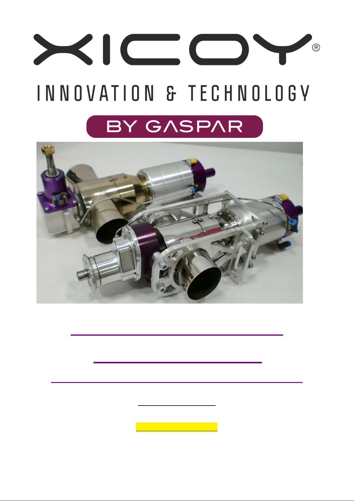
X icoy X45Helicopter
X45TurboProp
Two Stage Gas Turbine Engines
User Manual
Version 1.1 Aug / 2020
NEW!
NEW!
For 2020
For 2020
X45H
X45TP

Congratulations on your purchase of these new generation Xicoy X45 two stage gas turbine engines. We
are confident you will be delighted with your purchase and your new engine will give you excellent
service and maximum enjoyment to your hobby.
The X45 eli and X45TurboProp are a new extension of a very extensive research and development
programme by Gaspar Espiell & Xicoy Electronica SL supported by the latest fluid dynamics and
analysis software to bring you miniature gas turbine power units of unparalleled performance and
versatility in amazingly small packages. New electronics design and digital programming sets a new high
bar standard for this new generation of small turbine engines.
Much of the installation and operation of these engines is common to both units so we have combined
the instruction notes to a single manual to aid currency and completeness. Where instruction is specific
to one unit it will be stated.
This manual has been prepared to help you set up and safely operate your engine in your chosen
airframe. If you encounter any problems operating the engine then please consult this manual first and if
you cannot find a solution please get in touch with us.
If your problem is with a helicopter installation or operation of your chosen helicopter then please get in
touch with your install kit supplier.
ere is a contents list for this manual. Left click to fast access any section.
Contents
Xicoy X45 Helicopter and X45 Turboprop, two new engines to enjoy! 4
Xicoy X45 , two stage miniature helicopter engine............................................................................................... 4
elicopter Conversion Kits..................................................................................................................................... 4
Xicoy X45TP, two stage miniature TurboProp engine............................................................................................ 4
Features and Functions......................................................................................................................................... 5
Package Contents 6
elicopter engine:.................................................................................................................................................. 6
TurboProp engine:................................................................................................................................................. 6
New Owners 7
Legal...................................................................................................................................................................... 7
Disclaimer.............................................................................................................................................................. 7
Warranty 8
Shipping................................................................................................................................................................. 8
Warranty conditions............................................................................................................................................... 8
Performance, weights and measures 9
Installation – X45H Helicopter engine 10
Exhaust extensions.............................................................................................................................................. 11
Fitting the clutch................................................................................................................................................... 11
Installation – X45TP TurboProp engine 13
Cooling................................................................................................................................................................. 14
Exhaust extensions.............................................................................................................................................. 14
Installing the TurboProp....................................................................................................................................... 15
Propeller Selection (TurboProp)........................................................................................................................... 16
Component Installation Notes – All versions 18
Safety Notes 22
General Notes...................................................................................................................................................... 23
ECU Battery......................................................................................................................................................... 24
Page 2

Fuel...................................................................................................................................................................... 24
Oil........................................................................................................................................................................ 25
Engine Description 26
Engine.................................................................................................................................................................. 26
2nd Stage.............................................................................................................................................................. 26
Engine Control..................................................................................................................................................... 27
Component Description 27
ECU (Engine Control Unit)................................................................................................................................... 27
Connector board, the “ ub Lite” and “Compact ub”..........................................................................................28
Auto Power-Off.................................................................................................................................................... 28
Ambient Sensors.................................................................................................................................................. 28
Fuel Pump........................................................................................................................................................... 29
ECU Display 30
ub Lite data record / playback........................................................................................................................... 30
Plug-In backlit display.......................................................................................................................................... 31
Navigating Menu Screens 32
New Menu Items 37
Kero/Diesel selector............................................................................................................................................. 37
Pump min preset.................................................................................................................................................. 37
Max Power preset................................................................................................................................................ 37
Gearbox reduction............................................................................................................................................... 37
Governor constant RPM setting........................................................................................................................... 38
Propeller Overspeed Limiter................................................................................................................................ 38
Engine Installation: Electrical connections 38
Shared ECU battery............................................................................................................................................. 39
ECU Setup 40
eli Radio Special Notes..................................................................................................................................... 40
Turboprop radio setup.......................................................................................................................................... 41
Pre-setting Radio to ECU 41
Aligning transmitter with ECU.............................................................................................................................. 42
Failsafe................................................................................................................................................................ 43
Preparing the engine for running 43
Priming/purging the fuel system........................................................................................................................... 44
Starting Notes...................................................................................................................................................... 44
Starting the engine 45
elicopter engine running.................................................................................................................................... 45
TurboProp engine running................................................................................................................................... 46
Engine shut down procedure............................................................................................................................... 46
Adjusting the engine maximum power................................................................................................................. 47
AutoRestart function 47
What the auto-restart function does do................................................................................................................ 48
What the AutoRestart function will not do............................................................................................................ 48
Restart Disclaimer................................................................................................................................................ 49
Throttle curves (TurboProp) 50
Throttle stick position chart.................................................................................................................................. 50
Acceleration and Deceleration settings................................................................................................................ 50
ECU message codes 51
Diagnoses............................................................................................................................................................ 52
Diagnosis messages............................................................................................................................................ 52
Web site: www.xicoy.com Email: sales@xicoy.com
See our new turbine webpage at: www.Xicoyturbines.com
Page 3

Xicoy X45 Helicopter and X45 Turboprop, two new engines to enjoy!
Xicoy X45H, two stage miniature helicopter engine
This new power unit from the Xicoy stable is a miniature 2stage gas turbine helicopter drive unit to power
0.90cu in (15cc) size pod and boom size R/C helicopters. The unit features a miniature gas turbine
engine producing up to 3.5kw/4.7hp driving a 2nd stage turbine linked to a gearbox just like standard full
size practice. This offers a powerful, smooth and vibration free powerplant that can run on regular
kerosene. The sound is totally different from any piston engine, being smooth and steady with a gentle
rush of expanding air to provide a unique driving system unlike any other.
The unit is designed to interchange comfortably with standard 0.90 glow heli engines with considerably
more power available. Standard mountings, shaft attachments, fan and clutch parts may be reused with
minimal modification. The output rpm range matches closely with the benefit of a much higher reserve
torque and broader power curve making it easy match to any similar airframe.
The engine and gearbox unit is extremely small and light and easy to install and operate. It uses the
latest digital control with many additional safety functions developed specifically for this application. The
unit features a built-in constant head speed governor function eliminating fiddly pitch curve programming.
The unit is aimed at experienced helicopter fliers and is equally suited to sport and scale applications
with that unmistakeable scale turbine sound.
Helicopter Conversion Kits
Conversion kits are becoming available to convert standard glow engine airframes such as the Align 90
size “T-Rex700/800” or GoGlow 690 type R/C helicopter to this new power unit and we recommend this
route. (see the Xicoyturbines.com webpage for details of kits and supported airframes and brands).
Conversion kits alleviate the requirement to adapt components and airframe and install this unique gas
turbine power unit as all have already been resolved and included. Step by step instructions plus access
to help and support from like minded helicopter people greatly simplify the process. Installation becomes
a straight forward assembly task similar to assembly of the helicopter itself.
Xicoy X45TP, two stage miniature TurboProp engine
Xicoy are delighted to offer the X45TP, another 2 stage X45 TurboProp development utilising the 2stage
drive developed for the X45Heli. This unit benefits from very small size and light weight with a high
power output up to 5kw/6.7hp, equivalent to many 50cc piston engines making it ideal to power most
planes up to 2.5m/98” wingspan.
We have introduced this power plant complete with a sturdy mounting enabling it to easily fit standard
firewalls of airframes intended for bulkhead mounted 30 to 60cc petrol (gas) engines. A growing list of
airframe suggestions suited to the engine will be shown in the www.Xicoyturbines.com website.
The Xicoy 45TP is available in two reduction ratings, High and Low:
•High is for swinging large props at lower rpms for high wing Pilatus PT6 glider tug type
applications.
•Low is for fast flying sport “Tucano” or PC21 type models with limited ground clearance.
Depending on your planned airframe simply select the reduction rating for the propeller you plan to use.
Choice is if you plan to fly light and fast, or heavy and slow, a bit like the KV value for electric motors.
The gearboxes have been optimised to match each application and can be modified to opposite ratio by
replacing two of the gears, which can be done by customer. This enables us to optimise the performance
of the unit to the power curve of the 2nd stage and maximise your enjoyment of the unit.
Page 4

Features and Functions
•Tiny 60mm case 2 stage engine developing up to 5kw of shaft power
•Very low installed weight and bulk
•eli gearbox outline and shaft matches standard 90 size heli glow engine
•Turboprop version comes complete with bulkhead mounting
•Turboprop option of two reduction ratios: i = circa 6k and Lo = circa 8k
•2nd stage rpm feedback to ECU for constant speed governor function (heli)
•Gearbox over-speed protection function
•Gearbox output rpm and temperature included in telemetry feedback
•Accommodates wide presettable range of helicopter reduction ratios
•Peak power user presettable
•Valves and ECU installed on-engine
•Internal kero burner and thermocouple for clean exterior
•Compatible with diesel and kerosene
•Incredible start to idle of less than 25secs
•Fast spoolup to flight rpms
•Automatic cooldown after run, even with receiver power turned off
•Automatic battery disconnection after cooldown
•Brushless high speed starter
•Tiny intelligent brushless fuel pump
•igh speed digital control of all components
•Gearbox uses lubrication from engine, no separate oil required
•Choice of display options, on and off board and Bluetooth Android/iPhone
•Telemetry options available for most modern transmitters
New options and features are being added from time to time,
keep watching on: www.Xicoyturbines.com for details
Page 5

Package Contents
Helicopter engine:
Engine unit inc fod screen
Fuel pump
ub Lite + colour display + 300mm signal cable, OR / Compact ub
Engine cable 250mm
Battery cable
Servo type cable 300mm x 2
Aluminium filter
4mm tubing, 1mtr
USB memory card with instruction manual
TurboProp engine:
Engine unit inc mounting and fod screen
Fuel pump
ub Lite + colour display + 300mm signal cable, OR / Compact ub
Engine cable 500mm
Battery cable
Servo type cable 300mm x 2
Aluminium filter
4mm tubing, 1mtr
USB memory card with instruction manual
Page 6

New Owners
If you sell or pass on this engine to a 2nd or subsequent owner please also pass on this Users
Manual or its link, so they can enjoy a safe and fulfilling ownership too.
The Xicoy Electronica SL responsibility is limited exclusively to the repair of the engine and
accessories which are outlined in the conditions of warranty.
Before unpacking the engine, please read through these notes and agree to the conditions of
warranty.
Customer satisfaction is important to Xicoy Electronica. Technical support is readily available
through your local dealer and via email:
Xicoy Electronica SL, Plaça Pere Llauger Nau 18, 08360, Canet de Mar, Barcelona, Spain
Web site: www.xicoy.com Email: sales@xicoy.com
See our new turbine webpage at: www.Xicoyturbines.com
Legal
The engine design and contents of this User Manual are copyright Xicoy Electronica SL, Canet
de Mar, Barcelona, Spain. All rights are reserved.
This User manual, pictures and data are the property of Xicoy Electronica SL and cannot be
used or reproduced in any way with written permission from Xicoy Electronica SL.
Disclaimer
This engine is a very sophisticated piece of machinery. Great care should be taken at all times
when using the engine. It should only be operated installed in an airframe and by those with
appropriate skills and knowledge to do so. The engine is not a toy. Incorrect operation or misuse
can cause damage to property and serious bodily harm to operators, spectators or animals.
Xicoy Electronica SL accepts no liability any damage which may occur.
Xicoy Electronica SL assumes no responsibility for any errors contained in this document and is
not liable for any damages resulting from such errors.
It is forbidden to use this engine outside radio control applications, especially those that
power vehicles to carry people
Page 7

Warranty
The warranty duration for this Xicoy X45 or X45TP engine is two years from date of completed
purchase, or 25 running hours, whichever comes first.
•Warranty is valid solely for the original 1st owner and is non-transferable upon resale.
•Warranty includes all supplied parts and is limited to manufacturing defects only.
•Shipment costs forth and back, including packing and relevant customs fees are not covered by
the warranty, and will be at owners expense.
Damage or defective operation covered under warranty terms will be repaired and tested at no cost to
original owner (other than shipping expenses). Repairs not covered under the terms of warranty will be
carried out by Xicoy Electronica SL or their appointed agent after agreement of costs.
Shipping
Before returning the engine or ancilliary equipment for service or repair, please contact first your local
dealer or Xicoy Electronica SL Central Office to agree action and costs.
Do not ship before contacting Xicoy Electronica first
Shipping anything from outside the EU
without appropriate documentation will introduce delay and costs at customs borders
Warranty conditions
Please do not disassemble this engine or accessories (gearbox, pump etc) unless with express consent
from Xicoy Electronica SL. You will breach your warranty agreement and will find it an unfamiliar
sophisticated and precision assembly which you may not be able to reassemble without considerable
difficulty and specialist equipment. Simply slackening the compressor nut on the engine will lose the
delicate balance condition of rotor without which the engine may not run without sustaining damage to
the rotating assembly.
This warranty is voided if any one or more of the following conditions apply. In such a case Xicoy
Electronica SL will accept no responsibility for any damage or other consequence caused by engine
operation:
1. The product has been subject to operation using incorrect fuel, oil or fuel/oil mix.
2. The product is, or appears to be crash damaged, the fuel pump is blocked due to particle
ingestion, electronics or pump-drive are flooded with fuel or water ingress, connection leads are
cut or show loss of insulation and/or short circuit or reverse polarity on battery or engine cable
connection.
3. Unauthorized maintenance and/or modifications have been made to any part of the product;
including unlocking of the ECU and changing any of the manufacturers settings, or any items
supplied has or appears to have been disassembled.
4. Parts show damage by ingestion or entanglement of foreign object (wires or pipes, sand, grit and
small abrasive particles, water or fluids, dry powder from extinguisher).
5. The engine has or appears to have been operated incorrectly or not in accordance to this
operators manual.
6. The product has been or appears to have been misused, neglected or inadequately maintained.
7. The engine or fuel pump has or appears to have suffered damage or blockages in the fuel
system due to being run with unfiltered or contaminated fuel.
8. The engine and/or accessories show damage by physical contact with a corrosive substance
through operation or storage.
For further Information and updates on the X45H and X45TP engine and available
Xicoy Electronica help and support check our new dedicated turbine webpage at
www Xicoyturbines com
Page 8

Performance, weights and measures
X45Heli X45 TurboProp
Nominal power at sea level 3.5kw / 4.7hp 5kw/6.7hp
Idle shaft rpm 4,000rpm 1200 (low 11.1:1 ratio)
1000 (high 13.5:1 ratio)
Nominal max shaft rpm 20,000rpm (limited) 8krpm low ratio/6krpm high ratio
Governor RPM range Rotor 800-2,400RPM Propeller RPM Limiter >4k RPM
Torque at max rpm 1.5Nm (13 lb ins) 6.25Nm (55.3 lb ins) (low ratio)
8.33Nm (71.2 lb ins) (high ratio)
EGT at max power 350-450C 550 - 700´C
Fuel consumption at max power 100ml/min / 3.4oz/min 150ml/min / 5oz per min
Restart capability Off and manual Off, manual & automatic
Fuel Kerosene or diesel Kerosene or diesel
Oil mix required 4%, see text for breakdown 4%, see text for breakdown
Overall length: 280mm/11” 320mm/12.6”
Width across exhausts: 120mm/4.75” 120mm/4.75”
Width main body: 60mm / 2.35” 72mm / 2.83” (mounting)
Firewall to rear of prop distance n/a 160mm / 6.3”
Gearbox output shaft: Clutch portion 9.5mm / 3/8”, Dia 10mm plain portion, threaded
threaded 5/16” UNF M8x1.25 internally for M8 cap bolt
Gearbox mounting holes: 4 off dia 4.1mm 4 off dia 5mm, W86-90mm x 50mm
W52mm x 25mm (0.2”, 2” x 3.38-3.54”)
(0.164”, 2.05” x 0.98”) Firewall cutout required:
W72mm x 70mm (2.83”x 2.75”)
Unit weight bare 1170g/41oz 1470g/51.7oz (inc mounting)
Ancilliaries + Compact ub 70g/2.5oz 70g/2.5oz
ub Lite + display 86g/3oz 86g/3oz
ub Lite, no display 62g/2.2oz 62g/2.2oz
Airborne weight 1232g – 1261g 1532g - 1556g (inc mounting)
43.3oz – 44.3oz 53.9oz – 54.7oz (inc mounting)
Suitable ECU battery: 2S Lipo, min cap 1200mAh (recommended)
3S LiFe, min cap 1500mAh
Page 9

Installation – X45H Helicopter engine
Please read through the section on Safety as there are many
areas to consider that may differ from those pertaining to
other forms of helicopter power plant.
elicopters have a special form of vibration due to
assymetrical gyrations of the rotor head. We recommend
using a locking compound on any critical screws likely to
loosen in service. Use only blue type as the green type can
be impossible to loosen later. If you need to return your unit
for service, please remove clutch and fan assembly and any
mountings.
The unit is designed to operate with the output shaft uppermost. A side and plan view can be
downloaded from www.Xicoyturbines.com. Use the link to check for other sizes of mounting and views to
suit specific airframes as they become available.
NOTE To accommodate the housing expanding with temperature, the top bearing next to the fan is
allowed to slide against a strong internal load spring. Please note therefore that on installation, you need
to ensure there is no downward pressure on the output shaft which could overcome the spring and
cause the gears to bind which causes noise and excessive and rapid gear wear.
Use the standard clutch Retain and use the clutch supplied for the piston engine for the airframe. It
enables the engine to start and run to idle without powering the rotors. It also provides a valuable
slipping point in event of rotor being overloaded or forcibly stopped in a crash, or the helicopter being
blown over by strong gust of wind.
Keep gearbox cool The gearbox unit must be cooled in operation. Being connected to a gas turbine
producing up to 100kw of heat energy per second, it will otherwise quickly overheat in use. In operation
the fan drive will absorb some 500w which the engine can manage easily. If you planned to use a small
electric fan for the same purpose you will have to find an equivalent 500w of power to run it.
Use the standard fan The standard fan included with glow engine helicopters is suitable if used with
supplied shroud which can be trimmed to clear any areas of contact and direct the cooling flow
downwards onto the centre of the exhaust and gearbox. With an effective cooling setup the gearbox
temperature should seldom exceed 50C in operation, though may climb to 80C or more when engine is
stopped due to heat soak from the hot 2nd stage.
You can see if the fan is effective enough if the exhaust begins to turn a darker brown shade. Aim to
keep at least 6mm of shroud clearance to any hot surface. Consider the possibility that the fan shroud
may need to be fitted 1st, before the fan and clutch assembly.
Page 10
Exhaust extensions
In normal operation, the engine exhaust flow is continually expanding as it leaves the 2nd stage. Adding
extra exhaust ducting to the exhaust outlets inhibits the exhaust expansion and causes local restrictions
to the free flow, increasing the back pressure on the engine. This reduces the power available to run the
engine and has to be made up by burning more fuel. This therefore significantly increase the running
temperature and spoils the starting and running characteristics of the unit, so is strongly discouraged.
Where the standard exhaust outlet does not quite reach beyond the ends of a particular bodyshell short
simple push-on straight exhaust stubs up to 75mm/3” are acceptable as they cause minimal disturbance
to the engine flow. It is the longer lengths or changes in direction which cause back pressure and must
be avoided.
Fitting the clutch
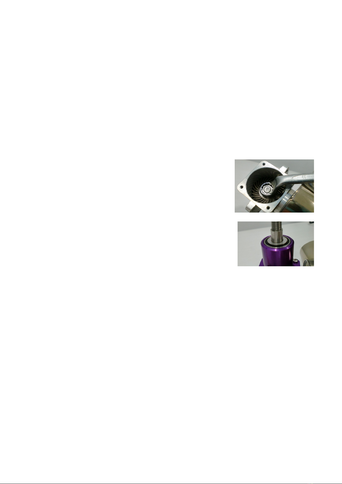
1. Fitting clutch. To fit the fan and clutch to the gearbox output shaft
you need to lock the output shaft. Do not attempt to do this by
jamming the 2nd stage turbine
2. Remove the four M3 screws from the bottom cap of the gearbox
to reveal access to the lower output shaft nut which you can hold
stopped using an 11mm socket wrench or ring spanner.
Be extra vigilant not to allow grit or dirt to enter while the cap is
removed. Be aware there may be some loose fuel in the gearbox
so best not do this on unprotected best dining table..
3. Place the 3/8” thin washer onto the output shaft first before the fan to ensure running clearance
to the top bearing.
4. A 12mm socket or box spanner can be used to nip the brass nut onto the fan. You can use a
washer if one was supplied in the heli kit but it is not usual. Do not use locking compound (Loctite
etc) on the brass nut. Do not substitute the brass nut, the shaft is stainless steel to prevent
rusting as is the brass nut.
5. Tighten the side nip screws on the split collet if used. Check fan rotates freely. Fit the clutch parts
and ensure everything is tracking true.
6. Refit bottom cap on gearbox (note orientation of cutout to clear input gear) using a small drop of
blue locking compound on the screws.
Page 11

7. Fit a good quality silicon or ptfe (heat resistant) 3 wire type
servo type cable from the small gearbox output pcb to
connect to the auxiliary socket on the small ub board. It may
be difficult to do this later. Note orientation.
When all is installed and powered up you can see a blue light
on the small gearbox pcb which when the shaft is rotated flashes twice per revolution to show
gear output shaft rpm signal present. When the gearbox is running fast the flashes indicate the
bus updating rpm signal every second.
8. Offer up the gearbox to the helicopter mountings following the special notes of your conversion
kit and carefully aligning the clutch into its bearing. Fit the gearbox securing screws but not tight
yet. Be very careful not to disturb or damage the lubrication feed pipe going to the gearbox from
the engine. If you have to remove it for any reason the 6mm gland nut on the gearbox should be
unscrewed to allow the pipe and gland to be removed as one. Note there are two small Orings
fitted onto the pipe which the gland nut presses down upon to provide the seal. When refitting
ensure the Orings are in position and the gland nut gently nipped up, don´t over tighten it not
needed.
9. The engine section should be supported by its special mounting in the airframe and the clutch
assembly checked for free rotation at this point. If all ok the mount screws can be fully tightened.
Never fly the eli without the engine properly supported in a sturdy mount, else even a gentle
landing can very expensively banana (bend) the 2nd stage unit in the middle. Always use the FOD
screen, elis throw up all sorts of ground debris, the small engine parts need all the protection
they can get.
Be careful to ensure no downward pressure load is placed on the output shaft when fitted to
airframe as this will jam the gears together and drastically shorten the life.
Don´t forget to fit the FOD screen
Page 12
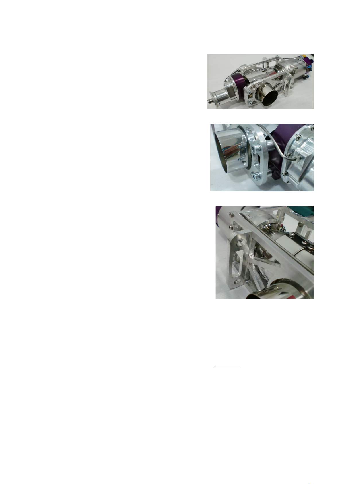
Installation – X45TP TurboProp engine
The engine unit is designed to operate horizontally with the
engine markings upwards. A side and plan view can be
downloaded from www.Xicoyturbines.com. Use the link to check
for other sizes of mounting and views and propeller sizes to suit
specific airframes as they become available.
Use the special mounting supplied as part the engine. It provides
critical support at the important positions required and aids heat
dissipation from the small gearbox. It also gives the engine
section gentle support and allows for expansion lengthways as
the unit warms up in operation. It also provides some limited
shielding from the hot interstage part between the engine and 2nd
stage.
Note the solid fixing of the gearbox to the mounting and through to
the firewall, critical in providing a stiff, yet load sharing pathway.
This simple but rigid framework provides a lot of engine protection
in event of a nose over or crash, however this stress will be passed
directly to the firewall so must be a secure point in the airframe.
Without such a system any significant prop-strike or nose over
could banana (bend) the 2nd stage, a very expensive repair.
A template is provided to place over and position mounting holes and cutout for the firewall. It can also
be downloaded from www.Xicoyturbines.com. Use the link to check for other sizes of mounting and
views to suit specific airframes and exhaust patterns as they become available.
The engine requires a flow of cool air to its intake to operate. This is ideally forward facing to take
advantage of prop and airframe airflow. Make provision for this separate from any airflow used for
cooling in the cowl area, perhaps passing underneath a separator. If this flow passes through the front
undercarriage area place a fine mesh similar to used on the fod screen to prevent stones, grass etc
being pushed into the engine area during ground manouvres.
Page 13

Cooling
In operation the 2nd stage radiates a lot of heat. The engine produces 100kw of heat per second, most
goes straight out the exhaust after giving up energy to the propshaft but some is retained by the 2nd
stage parts, meaning it gets very hot in the immediate area inside the cowl at the front of the airframe.
Allow plenty of propeller and forward flight airflow to be directed into the cowl area via openings and
vents just as you would a petrol or glow engine and this will keep the area well ventilated and help
prevent damage to surface finishes and/or paintwork. The ideal exit for this air is via side or lower vents
and a large clearance around the exhaust outlets of at least 6mm/1/4” is ideal to allow good outflow and
afford a limited amount of exhaust cooling. Be careful not to close off vent flow by the use of large
spinners or backplates.
It is important as noted earlier to minimize this hot cowl air reaching the engine intake as it raises the
engine running temperature significantly (an extra 1C at intake = approx 4C extra EGT), which is
detrimental to reliability and sensitive electronics are housed in the front of the engine.
Any required side or down-thrust for the powerplant is usually built into the firewall, so once the engine
unit has been positioned to place the propeller shaft in the centre of the cowl, the engine clearance hole
and bolt mounting holes can be cut out using the template. Protect any exposed wood using fuel proofer.
Allow a small clearance between the end of the cowl and the back of the propeller. Add a spacer to the
mounting position on the firewall if required, do not add a washer behind the propeller.
Exhaust extensions
As is also for the eli engine, in normal operation the engine exhaust flow is continually expanding as it
leaves the 2nd stage. Adding exhaust ducting beyond the exhaust outlets inhibits the exhaust expansion
and causes local restrictions to the free flow, increasing the back pressure on the engine. This reduces
the power available to run the engine and has to be made up by burning more fuel. This therefore
significantly increase the running temperature and spoils the starting and running characteristics of the
unit, so is strongly discouraged.
owever, where the standard exhaust outlet does not quite reach beyond a particular cowl or where you
want to turn the exhaust slightly to the rear for scale effect or streamlining, short simple Xicoy approved
push-on exhaust stubs are acceptable provided they cause minimal disturbance to the engine flow. It is
the longer lengths or significant changes in direction which cause back pressure and must be avoided.
Availability of approved exhaust extensions from various manufacturers will be noted on the Xicoy
website.
Page 14

Installing the TurboProp
1. Cut out holes for the exhaust, ideally positioned on any horizontal cowl split if there is one. Allow
6mm/1/4” clear all round.
2. Use M5 / no.10-32 nuts and bolts to fix the unit to the airframe, captive nuts are ideal.
Do Not fix the engine unit in place with woodscrews, it is impossible to ensure they cannot
loosen or pull through the firewall without warning.
3. Fit a good quality silicon or ptfe (heat resistant) 3 wire type servo type cable from the small
gearbox output pcb to connect to the auxiliary socket on the small ub board. It may be difficult
to do this later.
When all is installed and powered up you can see a blue light on the small gearbox pcb which
when the shaft is rotated flashes twice per revolution to show gear output shaft rpm signal
present. When the gearbox is running fast the flashes indicate the bus updating rpm signal every
second.
4. Offer the engine unit up to the firewall and secure in place with four screws, cap head type are
ideal as access is challenging.
5. Fit a previously carefully balanced propeller with 10mm bore onto
the shaft stub. See the chart on propeller selection to determine a
suitable size. If you plan to use a spinner backplate, fit this 1st.
For spinners Xicoy recommend “Truturn” prop backplates and
spinners for their accuracy and careful balance.
([email protected]) They have a wide range of adapters to suit
the unit – just mention you have an M8x1.25 prop bolt and they
should be able to help.
Important - No attempt should be made to add material, lead shot or coloured sticky tape
to balance the prop as this is sure to fly off later and if you are lucky it might not to hurt
someone, but the resulting out-of-balance running could cause major engine damage If
this happened in the air you would not know until it was too late The warranty will not
cover you for such damage
6. Fix prop (bore 10mm) in place using the supplied propwasher
and prop bolt. If the prop bolt is too long or short an alternative
standard M8 cap head type can be substituted. The propshaft is
threaded internally for a distance of 30mm (1-1/4”) and it is best
to have as much thread engaged in this as possible. This helps
steady the retaining bolt and prevent wobble.
7. Rotate the propeller gently and eyeball the tips from the side (don´t get too close..) to ensure
tracking is precise, and correct if not. Any run-out of the tips while under power will generate
severe unwanted vibration which can damage the gearbox.
8. Do the same with the propeller bolt, make sure its running true for the same reasons. Investigate
any wobble and cure.
Page 15

Propeller Selection (TurboProp)
The Xicoy TurboProp unit is useable to power in a wide variety of aircraft. Being available in two ratios
enables users to select the most appropriate for the intended application. The turboprop unit has been
tested in a range of situations and loads. The main indicator of the performance of the unit from the
users point of view, is the rpm that can be achieved with a given propeller load. Larger propellers and/or
more blades produce higher torque figures but not always the highest thrust figures.
We always recommend good quality wood props. Carbon are very nice but very unforgiving in a crash or
nose-over. Make sure the propeller is well balanced and the tips are visible (paint a strong colour) when
running, they can bite hard.
As the Turboprop has two reduction options there are optimum propeller sizes for each ratio.
igh reduction approx maximum, 6000rpm, ideal props 0.61-0.71m / 24-28”.
Low reduction approx maximum, 8000rpm, ideal props 0.51-0.61m / 20-24”.
igher rpms are achieved with smaller diameter propellers and / or shallow pitches. It is most important
that propellers significantly smaller than listed are not used or if they are, the maximum rpm limiter
should be preset to prevent overspeeding and possibly of overstressing (the propeller). In all cases
follow the propeller manufacturer’s recommendations for preparation and use.
Tipspeed
Most propellers are designed for a maximum tipspeed around 200m/s or 655ft/sec. Above this the tips
start to make that familiar howling noise. This can be just in a dive or most of the time if a prop with
shallow pitch is fitted to a fast airframe with a powerful engine.
A rough guide to optimum tipspeed is calculated by 3820 / prop dia in mtrs.
So for example a 610mm prop, max rpm would be 3820 / 0.61 = 6262rpm
For imperial measures 12,510 / prop dia in feet, or 150,100 / prop size in inches.
So for example a 26” prop max rpm would be 150,100 / 26” = 5773 rpm.
In practice the best performance comes from slightly overloading the engine with a slightly over-sized
propeller. This gives lower rpm on the ground but this is recovered as soon as the plane has forward
airspeed.
General notes on propellers
All sizes are 2 blades. If you want to use 3 or 4 blades, reduce by 50mm/2” on diameter:
Slow planes (Pilatus PC6 / Cessna highwing types) should ideally have a 26x10 or 28x8 pitch with 2
blades, and high ratio. Slow flying aerobatic planes can use the same.
Medium sports and scale plane like Pilatus PC7 / PC21 / Tucano needs a smaller diameter but larger
pitch, a 22x14 or 24x12 with high ratio, or 20x12 or 22x12 on low ratio. The larger diameter and pitch
enables plenty of thrust for good forward speed with a quiet operation and scale appearance.
Fast sleek plane needs a 20x14/16 or 22x14 pitch to get good forward airspeed. The larger pitch and
smaller dia allows a higher propeller rpm and corresponding high forward airspeed.
Prop-hanging requires large diameter and small pitch for high static thrust. Around 28x8 pitch is about
right with high ratio gearbox but the forward speed will not be high but takeoffs will be brisk.
Page 16

The dynamic thrust (when the aircraft is in flight) will reduce as aircraft airspeed increases and is a
function of all propeller driven aircraft. owever, it is worth reminding that the thrust on an unrestricted
turbo-prop falls off more gradually than an I/C engine due to the fact that as the propeller load reduces
due to forward speed (“unloading”) the propeller rpm rises 10-20% to balance the torque supplied. This
feature enables turbo-prop powered aircraft to achieve a higher forward speed than the static rpm
suggests, or the same speed achieved for a reduced throttle setting, saving fuel.
Activating the RPM limiter will reduce the whine up and down of a propeller on a plane doing aerobatics
in swoops and climbs so is worth setting. Note that as indicated earlier, in the air the prop will unload
quickly and can approach any preset rpm limit more easily so best is to set it slightly on the high side.
For example, a prop on the ground might give 5000rpm, you could set the limiter to 10% above this -
5,500 as the prop is sure to gain 10% in the air, it will be more like 20%. Experience will be your guide
here.
Maximum forward speed is mainly a function of forward thrust against airframe drag. A sleek and slippery
airframe will result in far greater airspeed on even modest power levels, whereas a large draggy airframe
may fly slowly on even exceptional power. Different brands of prop also add their own differences, some
appear more draggy than others or appear to make less thrust on the ground, but work well in the air.
Ground Clearance
If your plane has limited ground clearance then you can always go to 3 or 4 blade propellers. More pitch
may not be ideal with a slower flying model however.
Full-size “Pilatus PC7” – an ideal modelling subject for your new turbo-prop – who will be the first?!
Page 17

Component Installation Notes – All versions
Do NOT try to run the engine on its own. There is no need nor do we recommend attempting to run the
engine outside of the airframe by way of functional test. With care, the turboprop can be run on a sturdy
test stand with suitable propeller but there is no safe way to do so with the helicopter unit, and there is no
need. The engine has already completed a programme of test cycles at the factory in controlled
conditions. As this is not easy to do safely for your sake and can damage the engine unit by overheating
or overstress we strongly recommend you don´t.
1) You should have a clear idea how to arrange all the components needed to run the engine inside
the model. The main issues are fuel tank (locate centre of tank to CofG), bubble trap position (if used),
locating the fuel pump in close proximity to the source of the fuel (bubble trap or tank) and adjusting the
receiver and ECU batteries to achieve optimum location for balancing the model.
2) The 3-wire heavy connecting cable from the engine to the ub should be carefully routed away
from the engine intake so there is no possibility of the wire being accidentally ingested if the FOD screen
should be displaced for any reason. This is 250mm (10”) on the eli and 500mm (20”) on the Turboprop.
Please do not modify it if not quite right, ask for a longer or shorter one if required. Avoid placing the
cable close to the engine rpm sensor which is located at approximately 4 O´clock when viewed at the
intake of the engine with the cable entry plug at 12 O´clock. A cable too close can cause some rpm
interference at start-up. The same goes for any servo wires or servos passing near.
3) The 4mm fuel feed pipe should be routed similarly clear of the intake. Try to have at least
200mm/8” of fuel feed pipe to the engine. Note the connector is indicated with an “F”.
4) The metal lubrication feedpipe to the gearbox, exits the engine via the connector marked “L”.
Be sure NOT to accidentally connect the fuel feed to this if removed.
5) The other end of the engine cable should plug into the
small ub connector unit sited at a convenient (cool) location
for access. You can use the regular small ub ( ub Lite) or the
Compact ub with the screen built on, both have same
function. This is also the location to connect the ECU battery.
6) If you plan to use a telemetry adapter it should plug into
the outlet marked “Data Port” on either ub unit. Mount it somewhere away from heat, and visible if
desired. If also using the colour display you can connect both using a Y lead.
Page 18

7) The signal cable from the gearbox rpm sensor should be plugged in alongside the pump outlet
with the same orientation. On the Compact ub it is marked “Aux”. There is no specific marking on the
ub Lite but it should go below the pump outlet.
8) If the ECU battery has to be sited at some distance perhaps in the tail for a heli, please contact
Xicoy and ask for a longer cable in one piece. Please don´t cut it and splice in a couple of old bits of wire
to make it longer as this is surely a recipe for troubles and is a regular candidate on engines presented
for service. A heavy duty extension can be used but check polarity before plugging in. Its always better to
have a longer single piece cable for minimum volt drop and maximum reliability.
9) The ECU battery should ideally be sited somewhere it can be easily accessed. It is good practice
to disconnect after flight or before travelling anywhere with the model.
Note it is extremely important to disconnect the battery whilst charging, as the usual pulse type
charger can easily destroy the ECU, and is in any case a sensible precaution with rechargeable
batteries
10) The centre of the fuel tank should be located as close to the centre of gravity (CofG) of the
model as possible. This will minimize the effects of the CofG shifting as the fuel is used during the
flight.
11) The fuel tank should have an effective fuel pickup, like a felt clunk or felt bag over a weighted
clunk to ensure no air is pulled into the fuel feed. A UAT or similar can be used.
Fuel Pump
Air Trap
Fuel Tank
Fill point
Vent
A bubble-trap (like the Xicoy and BVM models “UAT”) type hopper tank system is highly recommended
(and available in the Xicoy Jet Shop). The bubble-trap outlet feeds direct to the inlet to the filter. If using
an air trap which has a fine bag type filter (Xicoy) then the external filter CAN be omitted but beware the
pump is vulnerable to particles getting in between bubble trap and pump inlet, so aim to be squeaky
clean with the installation.
12) A tank capacity of around 800cc/30oz to 1000cc/35oz is suitable for 6-10mins flying for
helicopters, and 1200cc/40oz to 1500cc/50oz suitable for the same times on turboprops.
Page 19

13) The fuel pump should be located close to the fuel tank as convenient. The pump has two 3mm
screw fixing holes provided for mounting to the airframe. Try not to mount the pump in close proximity to
the front of the engine as being a brushless motor it might interfere with the rpm reading. If you want to fit
a manual shutoff, fit a Festo 4mm type in the pressure side and locate it somewhere easy to see and get
to.
14) To prime the fuel system, disconnect the fuel pipe at the engine and route it into a suitable
container. Run the fuel pump for a few seconds using the Pump Prime function accessed via the INFO
menu. Note the ECU battery must be connected to do this. This will help clear any air and particles that
could have entered the fuel system during installation.
15) If refitting a quick release “Festo” connection, trim the last 6mm (1/4”) from the end of the tube to
expose a fresh area for the connector to seal onto. To release a “Festo” type connection, push the blue
ring inwards with one hand and gently pull the tube out with the other hand, whilst holding the collar in its
retracted position.
16) If using “Tygon” flexible piping from fuel tank push on a short (12mm/1/2”) length of the supplied
4mm pipe onto the pump suction port and push the “Tygon” over the top to provide a tight leak free
fitting. A double wrap of lock-wire will ensure secure connection. Otherwise, use the 4mm piping
supplied. DO NOT use tie wraps anywhere on the fuel system. Be aware Tygon gradually softens in use
so should be replaced annually.
17) DO NOT use “Tygon” flexible piping anywhere for the pressure (delivery) side, it is only suitable
on the suction side. Also DO NOT use silicon tube anywhere in the fuel system as the fuel will melt it.
18) Any air inlet openings to the engine intake should have area equivalent to 62mm x 62mm /
2.5”x2.5”“.
19) Extreme care should be taken to avoid the possibility of foreign objects, loose parts or debris
being allowed to enter the engine either during installation or while flying. Always use the supplied FOD
screen but regard this as a last line of defence and not as a reason not to practice good housekeeping.
Before filling the tank and starting the engine for the first time, turn the model upside down and give it a
good shake and hoover out to loosen and clear any small bits and pieces.
20) Always use the supplied FOD screen, it protects the engine from sucking in small objects that
could damage the delicate high speed compressor blades.
Page 20
This manual suits for next models
3
Table of contents
Other Gaspar Engine manuals


Popular Engine manuals by other brands


Morini Franco Motori
Morini Franco Motori S6-C COMPETITION Service manual

Mercury
Mercury Inboard 5.7L manual

Craftsman
Craftsman 143.996524 Operator's manual

TDI
TDI TURBOTWIN T30ML Installation and operating manual

ASA Electronics
ASA Electronics MARCONI 50 PS manual

Altronic
Altronic CD200D installation instructions

MTU
MTU 20 V 4000 C22 operating instructions

Tecnotion
Tecnotion QTR 65 Series manual

Nice
Nice RDF Series Instructions and warnings for installation

SUHNER ABRASIVE
SUHNER ABRASIVE UAD 25-RF Technical document

Atlas Imperial Diesel Engine
Atlas Imperial Diesel Engine Engine Operator instructions

Briggs & Stratton
Briggs & Stratton 124L00 Series Illustrated parts list