REV.03-(16.03.2015)
4.1.6 WATER SIDE CONNECTION INSTRUCTIONS
The heatng capacty of the unt must be prevously establshed
by calculatng the buldng's heat requrement accordng to
current regulatons. The system must be provded wth all the
components for correct and regular operaton. In partcular,
provde for all the protecton and safety devces prescrbed by
current regulatons for the complete system.
We strongly recommend to nstall two ball valves
under the boler, so the boler can be solated from
the heatng system when needed.
4.1.7 EXPANSION VESSEL
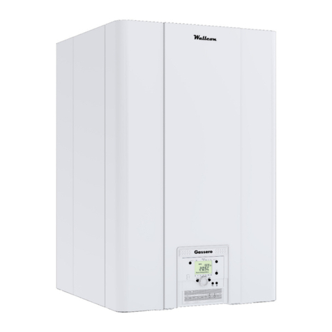
Wallcon 115 s not suppled wth an expanson vessel;
therefore ts connecton must be carred out by the qualfied
nstaller. The capacty of the expanson vessel must be chosen
and nstalled to match the capacty of the central heatng
system and the statc pressure. We suggest you nstall the
expanson vessel n the return lne of the central heatng
system. It can be combned wth the dran valve for servcng.
4.1.8 SAFETY VALVE
Safety valve outlet must be connected to collecton ppe to
prevent water spurtng onto the floor n case of overpressure
n the heatng crcut. Otherwse, f the dscharge valve cuts n
and floods the room, the boler manufacturer cannot be held
lable.
4.1.9 CONDANSATE DISCHARGE
The condensate dran s n the left sde at the bottom of the
boler and has a 25mm hose dscharge. Connect ths flexble
hose to the sewer system. Use only plastc parts wth the
condensate dran. Metal lnes are not allowed. Blockage of ths
dran may cause damage to the boler. The dran connecton s
correct when the condensate can be seen flowng away, e.g.
usng a funnel. Any damage that may occur s not covered by
the warranty of the boler. There should be an open connecton
between the condensate hose from the boler, to the sewage
system. An under pressure n the sewage system should never
be able to suck on the boler condensate dran hose. The
condensate dran must be connected n accordance wth
current regulatons.
Do not use the water system ppes to earth electrcal
applances.
4.1.10 FROST PROTECTION
Wallcon seres boler has bult-n frost protecton, automatcally
actvatng the central heatng pump when the boler return
water temperature drops below 5°C. The pump and/or burner
wll shut down as soon as the return temperature has reached
demanded pont. The above-mentoned temperatures relates
to the temperature measured wth the RETURN sensor of the
boler. Ths Frost Protecton provson s for the boler only and
not for the all system.
4.1.11 DIRT SEPERATION
Always nstall a straner (water filter) and /or a drt separator n
the return of the boler s such a way that the boler water s free
of any debrs/partcles. When usng a water filter one should
check weekly after nstallaton to determne the straner cleanng
nterval.
Instructons for the nstaller
13
ncludng an ar bleed valve so the straner can be solated from
the heatng crcut for servcng. Clean water s mportant,
blocked heat exchangers do not fall under warranty. The filter
should be nstalled when replacng bolers n exstng systems.
The manufacturer declnes any lablty for damage caused to
the boler by falure to nstall or nadequate nstallaton of
ths filter. Before swtch on the boler, water must be crculate at
least 2 hours for elmnaton the mpurtes from the system
trough the mcro mpurty seperator. In the end of the operaton,
safety dran valve must be opened for removng the mpurtes.
It s also possble to use plate heat exchangers accordng the
system characterstcs. In any case, mcro mpurty seperators
must be used n the system n the boler. Before nstallaton,
carefully wash all the ppes of the system to remove any
resduals or mpurtes that could affect proper operaton of the
unt. Flter must also be nstalled on the system return ppng to
prevent mpurtes or sludge from the system cloggng and
damagng the boler.
We advse to mount valves before and after the straner
There s an automatc ar vent mounted n the boler to remove
ar from the water crcut. Ths automatc ar vent s only for
elmnate the ar n the heat exchanger of the boler. One or more
external automatc ar vent(s) and/or ar separators should
always be nstalled n the heatng system to elmnate ar trapped
n the heatng crcut.
4.1.13 PUMP
The WALLCON 115 bolers are suppled wth a bult-n
crculaton pump wth 3-poston electrc speed control. The
pump s the sngle-phase type (230 V - 50 Hz). To ensure
optmal boler operaton, n the case of new systems (sngle
ppe and module) t s recommended to use the pump at
maxmum speed. The pump runs when heat s requred. When
heat s no longer requred, the pump wll contnue to run for
another 3 mnutes before t stops. The 24-hour cycle starts as
soon as the power supply to the boler s actvated.
4.1.12 AUTOMATIC AIR VENT
Drt
seperator
Ar
seperator
Low loss
header
Plate heat
exchanger
Flter
0
1
2
3
4
5
6
7
H
[m]
0
10
20
30
40
50
60
70
[kPa]
p
0 1 2 3 4 5 6 7 8 Q [m /h]
QH Chart
3


