GasTech IQ Express User manual
R eferenc e M a nua l
IQ E xpres s
D oc king S ta tion
for
ToxiP ro, Tox iLtd
& Toxi3Ltd
Gastech
24 Baretta Rd
Wangara Western Australia 6065
Tel 1800 999 902
Fax 1800 999 903
http://www.gastech.com

1
THE IQ EXPRESS IS DESIGNED TO INTERFACE WITH SPERIAN
INSTRUMENTATION GAS DETECTORS.
SPERIAN INSTRUMENTATION GAS DETECTORS HAVE BEEN
DESIGNED FOR THE DETECTION OF DEFICIENCIES OF OXYGEN,
ACCUMULATIONS OF FLAMMABLE GASES AND VAPORS AND
ACCUMULATIONS OF TOXIC VAPORS.
IN ORDER TO ENSURE THAT THE USER IS PROPERLY WARNED OF
POTENTIALLY DANGEROUS ATMOSPHERIC CONDITIONS, IT IS
ESSENTIAL THAT THE INSTRUCTIONS IN THIS MANUAL AND THE
OPERATIONS AND/OR REFERENCE MANUAL(S) FOR THE GAS
DETECTOR(S) BE READ, FULLY UNDERSTOOD, AND FOLLOWED.
THIS MANUAL IS NOT INTENDED TO REPLACE THE OPERATIONS
AND/OR REFERENCE MANUALS FOR THE GAS DETECTOR. THIS
MANUAL IS ONLY DESIGNED TO AID IN THE INSTALLATION AND
OPERATION OF THE IQ EXPRESS SYSTEM AND SHOULD BE USED IN
CONJUNCTION WITH THE INSTRUMENT REFERENCE OR
OPERATIONS MANUAL AT ALL TIMES.
IQ Express Reference Manual
Sperian Instrumentation Part Number 13-275
Version 4.02
Copyright 2008
by
Sperian Instrumentation, LLC
Middletown, Connecticut 06457
All rights reserved.
No page or part of this operation manual may be reproduced in
any form without written permission of the copyright owner
shown above.
Sperian Instrumentation reserves the right to correct typographical errors.

2
Table of Contents
Warnings and Cautions ........................................................................................ 3
A. Signal Words...................................................................................................................3
1. Overview ........................................................................................................ 4
1.1 Tests and record keeping ...........................................................................................4
1.2 PC Connection ............................................................................................................4
1.2.1 USB Connection..........................................................................................................4
1.2.2 Ethernet Connection and E-mail.................................................................................4
1.3 PC Requirements........................................................................................................5
1.3.1 Ethernet Requirements........................................................................................5
1.4 Instrument Firmware Requirements ...........................................................................5
1.5 Power Requirements...................................................................................................5
1.5.1 Dock with direct USB Connection to PC .............................................................5
1.5.2 Multi-Dock Setup with USB Connection..............................................................5
1.6 Sensor compatibility....................................................................................................5
1.7 Default Calibration Gas Settings and Dock Compatibility ..........................................6
1.8 Calibration Gas Cylinder Regulator Requirements.....................................................6
1.9 Delivery .......................................................................................................................6
2. Installation ..................................................................................................... 6
2.1 Installation Overview...................................................................................................6
2.2 IQ Administrator Pro and PostgreSQL Database Server Installation.........................6
2.3 IQ Database Manager Software Installation...............................................................7
2.4 IQ Express PC Software Installation...........................................................................7
2.5 Install IQ Administrator Pro and PostgreSQL database. ............................................8
2.6 Power and Connectivity ..............................................................................................8
2.6.1 PC – Single Dock via USB ..................................................................................8
2.6.2 PC – Multi Dock via USB.....................................................................................8
2.7 Connecting the Calibration Gas Cylinder(s) to the Dock(s)........................................9
2.7.1 Single Cylinder to Single IQ Express Dock .........................................................9
2.7.2 Single Cylinder to Multiple Docks......................................................................10
2.7.3 Fresh Air Port Instructions .................................................................................11
Fresh Air Filter...............................................................................................................11
Providing Fresh Air in a Contaminated Environment ...................................................11
Option 1: Using a Gas Cylinder to Provide Fresh Air to the Dock...........................12
Option 2: Using a Sealed Conduit to Provide Fresh Air to the Dock.......................12
Multi-Dock Setups with Fresh Air Manifold...............................................................12
2.8 Dock Setup................................................................................................................13
3. Software ....................................................................................................... 13
3.1 Dock Status ...............................................................................................................14
3.1.1 Dock status LED ................................................................................................14
3.1.2 Instrument status LEDs .....................................................................................14
3.2 Dock Controls and Instrument Status .......................................................................15
3.2.1 Dock Configuration ............................................................................................15
Hardware Configuration................................................................................................15
AC Power ......................................................................................................................15

3
LCD Contrast Control....................................................................................................15
Battery...........................................................................................................................16
Pump Diagnostics .........................................................................................................16
Audible Alarm Sensitivity Controls................................................................................16
Calibration Interval ........................................................................................................16
Gas Configuration .........................................................................................................16
Special Instructions: Gas Configuration, Oxygen Detectors .......................................17
Saving new settings ......................................................................................................18
Dock LCD Display.........................................................................................................18
Ethernet Controls ..........................................................................................................18
3.2.2 Instrument Tab...................................................................................................18
3.3 Advanced Settings / Passcode .................................................................................19
4. Dock Use...................................................................................................... 20
4.1 Test Sequence ..........................................................................................................21
4.2 Loss of IrDA Connection ...........................................................................................22
4.3 Test Failures .............................................................................................................22
4.3.1 No gas detected ................................................................................................22
4.3.2 Span calibration failure......................................................................................22
4.3.3 Wrong Gas Type ...............................................................................................22
4.3.4 Alarm test failure................................................................................................22
4.3.5 PC Aborted Test ................................................................................................22
5. Tools............................................................................................................. 22
5.1 Dock ..........................................................................................................................23
5.2 ToxiPro ......................................................................................................................23
5.3 Certificates ................................................................................................................24
5.4 Session Downloading ...............................................................................................24
6. Software Revisions ..................................................................................... 24
Appendix A: USB Architecture with Network Access..................................... 25
Appendix B: Calibration Frequency ................................................................. 26
Sperian Instrumentation Warranty Gas Detection Products........................... 27
Warnings and Cautions
A. Signal Words
The following signal words, as defined by ANSI Z535.4-1998, are used in the IQ Express
Reference Manual.
indicates an imminently hazardous situation which, if not
avoided, will result in death or serious injury.
indicates a potentially hazardous situation which, if not avoided,
could result in death or serious injury.
indicates a potentially hazardous situation, which if not avoided,
may result in moderate or minor injury.
CAUTION used without the safety alert symbol indicates a potentially hazardous
situation which, if not avoided, may result in property damage.

4
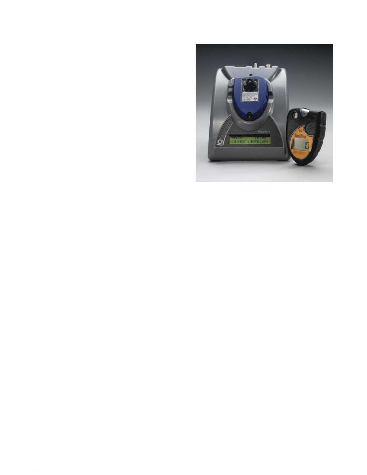
1. Overview
The IQ Express is an automatic calibration
station for use with the ToxiPro, OxyPro,
ToxiLtd and OxyLtd Gas Detectors. The IQ
Express automatically performs up to eight
critical tests including sensor identification,
instrument performance, bump and alarm
tests and necessary record-keeping
procedures. The station retains a historical
record of instrument testing in the system's
onboard memory.
The IQ Express Dock is available in two
versions. The standard version is able to
process instruments containing O2, CO and
H2S sensors. The enhanced version adds
the ability to process ToxiPro instruments
for SO2, Cl2, NO2, NH3, HCN and PH3.
Either type of dock may be operated as a
stand-alone calibration station, or may be
connected to a PC via USB or Ethernet for
increased control over system operations.
When the IQ Express is operated without a
PC interface, it will operate with the last set
of calibration gas settings that were
uploaded into the instrument and will
automatically store data until its memory is
full.
Unless specified at the time of purchase, all
IQ Express Docks are shipped from Sperian
Instrumentation configured for CO/H2S
instruments with standard calibration gas
settings. In the event that the dock is to be
used as a stand-alone calibration station for
an instrument with a gas other than CO or
H2S, or requires a non-standard calibration
gas setting, the dock must be
reprogrammed with the IQ Express PC
Software.
The IQ Express PC Software must be
loaded onto the PC prior to completing the
physical connection to the PC. When
connected to the PC, the IQ Express will
automatically upload all instrument data into
the PC whenever the instrument is placed in
the dock.
Note: Do not connect the IQ Express to
the PC until the software has been
installed and the PC has been restarted.
1.1 Tests and record keeping
The IQ Express Station automatically
performs the following eight procedures
whenever an instrument is placed in the
dock.
•Instrument identification
•Battery test
•Audible alarm test
•Visual alarm test
•Vibrating alarm test (if applicable)
•Fresh air calibration
•Bump test
•Record-keeping
•Datalogger and Eventlogger download
(IQ Express must be connected to PC to
extract the information from the dock)
In the event that an instrument fails the
bump test, or if the instrument’s calibration
due date has passed, the IQ Express will
automatically proceed to a full calibration
without further intervention from the user.
If the instrument fails any of the tests listed
above, the IQ Express will notify the user
through the display on the dock, and
through the PC if the dock is connected to
the PC and the software is running.
Results of tests and calibration attempts are
stored in the dock and uploaded to the PC if
the software has been loaded and the USB
or Ethernet connection is active.
IQ Express software versions greater than
3.0 will have the ability to download the
contents of the instrument’s datalogger and
eventlogger into a file on the PC that may
be opened with BioTrak software. The IQ
Express must be connected to the PC for
the download to occur.
IQ Express software versions greater than
6.20 have the ability to update the ToxiPro’s
firmware/flash file.
1.2 PC Connection
1.2.1 USB Connection
To enable the interface from the IQ Express
to the PC, first install the IQ Express
Configuration Software and IQ Database
Manager Software. Then connect the PC to
the IQ Express Dock with the USB cable
that is included at the time of purchase.
See section 2 for more detailed setup
instructions.
1.2.2 Ethernet Connection and
E-mail
IQ Express Docks with the Ethernet
upgrade may be connected to the PC via
USB or via a network. To connect via
Ethernet, follow the directions given in the
IQ Express Ethernet Instructions booklet.

5
Docks that are connected by Ethernet have
additional controls at the PC to ping the
dock, to view the Ethernet settings and to
view and test the e-mail system.
E-mail may be sent by the dock to a single
e-mail address when a fault is detected at
the dock, but for no other reason. The dock
must be connected to a network via
Ethernet for the e-mail function to work. E-
mail capability is controlled entirely through
the IQ Database Manager Pro program. For
more information on the e-mail function see
Ethernet Controls in section 3.2.1 below or
the IQ Database Manager Pro manual.
1.3 PC Requirements
•Pentium Processor 1.0GHz or better or
equivalent.
•256MB RAM.
•Windows 2000 Pro / XP / Server 2003
•50MB hard drive disk space.
1.3.1 Ethernet Requirements
To be Ethernet compatible, the IQ Express
Dock must have Flash version 4.00 or
higher and must be equipped with an
Ethernet port.
PC Software must be version 4.00 or higher
to support Ethernet connections.
1.4 Instrument Firmware
Requirements
Instrument firmware version 4.3 or higher is
required in the ToxiPro, OxyPro, ToxiLtd or
OxyLtd for compatibility with the IQ Express.
Firmware upgrades to the ToxiPro and
OxyPro may be made with a PC through the
IrDA port. Instrument firmware upgrades
are available free of charge through Sperian
Instrumentation’s download website:
http://www.biodownloads.com
ToxiLtd and OxyLtd instruments must be
returned to Sperian Instrumentation for
firmware upgrades. Call Sperian
Instrumentation for a Return Authorization
number (RA#) before shipping.
1.5 Power Requirements
Power requirements for IQ Express Docks
vary with the number of docks and the type
of connection.
If the dock is to operate as a stand-alone
calibration station, or if the dock is to be
connected via Ethernet, the IQ Express
must be plugged in to an appropriate
electrical outlet using the power supply /
wall cube that was included with the dock at
the time of purchase.
If multiple IQ Express docks are purchased
with the IQ Express Mounting Bracket, an
optional power supply is available that is
capable of running up to four IQ Express
Docks from a single electrical outlet.
For docks that will remain connected to the
PC via USB Port, follow the relevant
instructions below in section 1.5.1 or 1.5.2.
The IQ Express Dock is delivered with an
appropriate power supply, which should be
specified at the time of purchase.
•100-120 VAC, 60Hz, 9A
•200-240 VAC, 50Hz, 4.5A
If the power supply includes a voltage input
selector switch, be sure to set the switch to
the appropriate voltage for your electrical
supply.
Note: If the IQ Express Dock(s) is to be
installed on the IQ Express Mounting
Bracket, follow the instructions that were
sent with the bracket.
1.5.1 Dock with direct USB
Connection to PC
If each IQ Express Dock can be given its
own USB port and connected directly to the
PC via USB cable, then the PC will provide
enough power to run the dock(s).
1.5.2 Multi-Dock Setup with USB
Connection
For multi-dock configurations, Sperian
Instrumentation recommends the use of a
powered USB hub, which is able to power
multiple USB devices directly through their
USB cables.
Under no circumstances can multiple IQ
Express Docks be run from a single USB
port without supplemental power.
Power and Connectivity are discussed in
greater detail in section 2.6.
1.6 Sensor compatibility
Standard versions of the IQ Express Dock
are capable of processing instruments
containing the following sensor types: O2,
CO and H2S.
Enhanced versions of the IQ Express Dock
are capable of processing instruments with
all of the sensors listed above plus ToxiPro
instruments for SO2, Cl2, NO2, NH3, HCN
and PH3.

6
1.7 Default Calibration Gas
Settings and Dock
Compatibility
Dock
Setting
Default Cal Gas
Setting
Dock Type
S=Standard
E=Enhanced
CO 50 PPM S,E
H2S 25 PPM S,E
CO / H2S 50 PPM CO /
25 PPM H2S
S,E
SO210 PPM E
Cl210.0 PPM E
NO25.0 PPM E
NH350.0 PPM E
HCN 10.0 PPM E
PH35.0 PPM E
Default Calibration Gas Settings and
Dock Requirements
1.8 Calibration Gas Cylinder
Regulator Requirements
A demand-flow regulator must be used with
the IQ Express.
1.9 Delivery
Each IQ Express Calibration Station is
delivered with the following items:
•IQ Express
•IQ Express Configuration Software
•IQ Database Manager Software
•USB Cable
•Power Supply
•Standard versions are delivered with a
2’ piece of calibration gas tubing with
pre-installed white quick disconnect
fitting.
•Enhanced versions are delivered with a
calibration gas tubing assembly
comprising a 1” piece of standard tubing
connected to a black elbow fitting, which
is then connected to a 2’ long piece of
smaller diameter tubing with pre-
installed white quick disconnect fitting.
2. Installation
The IQ Express must be configured with a
PC prior to use. Once the dock has been
configured, it may be used as a stand-alone
calibration station without a PC connection,
or connected to a PC via USB cable or
Ethernet for increased control over system
operations.
Note: If the dock is configured for an
Ethernet connection, specific
instructions for Ethernet are included
with the dock.
Unless otherwise specified at the time of
purchase, all IQ Express Docks are shipped
from Sperian Instrumentation configured for
CO/H2S instruments with the standard
calibration gas settings.
If the user chooses to activate the IQ
Express without a PC connection, or if the
PC connection has been lost, the dock will
operate with the last set of calibration gas
settings that were uploaded into the
instrument and will automatically store
calibration data until the onboard memory is
full.
Note: Do not connect the IQ Express
Dock to the PC until the IQ Express and
IQ Database Manager Software have
been installed and the PC has been
restarted.
2.1 Installation Overview
1. Install the PostGreSQL Database and
the IQ Administrator Pro program. See
section 2.2 below.
2. Install the IQ Database Manager
program as described in section 2.3.
3. Install the IQ Express PC Software as
described below in section 2.4.
4. Use Administrator Pro to create a
default PostgreSQL database as
described below in section 2.5.
5. Follow the instructions in section 2.6 for
connecting the IQ Express Dock(s) to
the PC via USB. Follow the Ethernet
Instructions booklet if connecting by
Ethernet.
6. Follow the instructions in section 2.7 for
connecting the calibration gas cylinders.
7. For docks that will be connected
permanently by USB port, configure the
docks by connecting them to the PC’s
USB port. For an Ethernet connection,
follow the Ethernet Instructions that
came with the dock.
See Appendix A for the USB Connection
Diagram.
2.2 IQ Administrator Pro and
PostgreSQL Database
Server Installation
The IQ Administrator Pro Program is
contained on the IQ Express Installation
Disk. Place the disk in your PC’s CD tray
and follow the installation instructions given
7
in the IQ Administrator Pro Reference
Manual that is included with the IQ Express
Dock.
2.3 IQ Database Manager
Software Installation
The Database Manager Pro Program is
contained on the IQ Express Installation
Disk. Place the disk in your PC’s CD tray
and follow the installation instructions given
in the IQ Database Manager Software
manual that is included with the IQ Express.
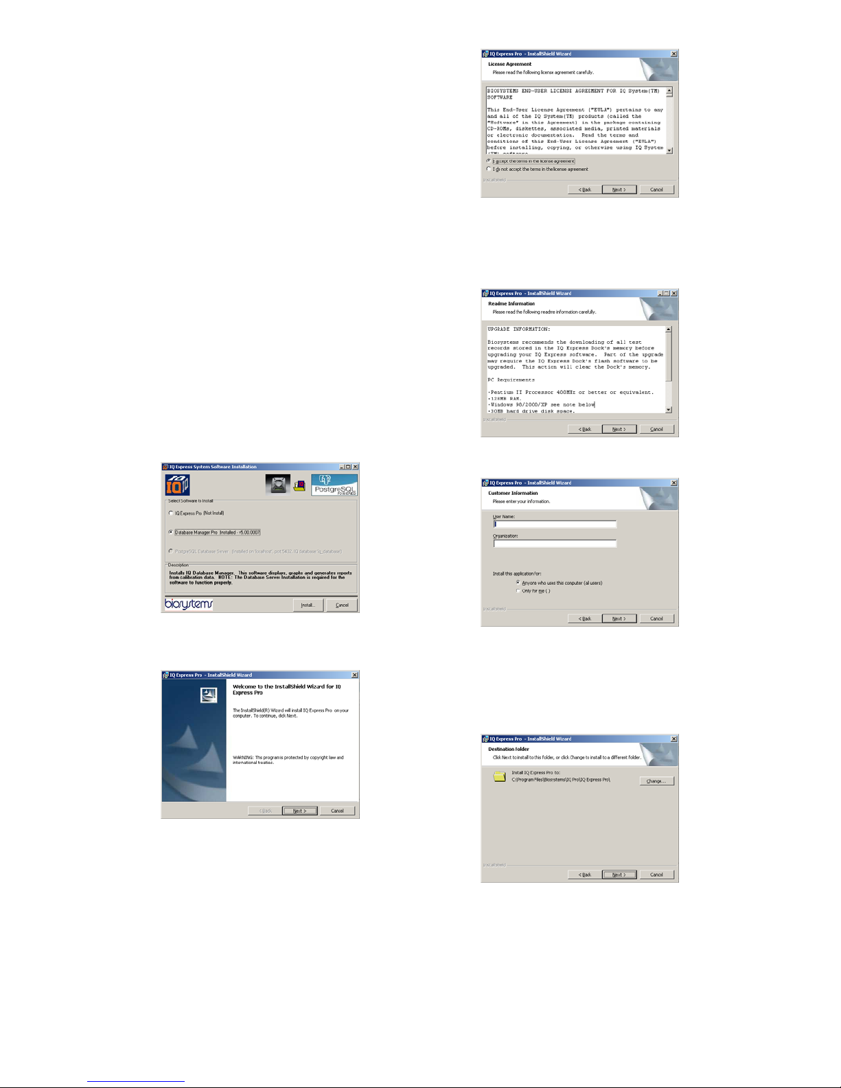
2.4 IQ Express PC Software
Installation
Note: Screens shown below may be
slightly different depending on your PC’s
operating system.
1. The Software Installation screen should
come up automatically once the
installation of Database Manager is
complete. If this screen does not come
up, access the CD drive using Windows
Explorer.
2. Select IQ Express Pro and click “Install”.
The InstallShield Wizard will begin the
installation.
3. Click “Next” to continue with the
installation. The Licensing Agreement
screen will be shown.
4. If you accept the terms of the License
Agreement, click “I accept.....” and then
click “Next” to continue. The upgrade
information and PC requirements will be
shown.
5. Click “Next” to continue. The Customer
Information screen will be shown.
6. Enter the name of the user and the
name of the organization. Then select
whether this application may be used by
“Anyone who uses this computer” or
“Only for me”. Then click “Next. The
destination folder screen will be shown.
7. To install IQ Express in the default
directory at “C:\Program Files \
Biosystems \ IQ Express”, simply click
“Next”. To install the files to another
directory, click “Browse” and use
Windows Explorer to specify the new
location. Click “Next” once this is

8
accomplished. The following screen will
then be shown.
8. Click “Next” to continue. The status of
the file decompression will be shown.
Once the installation is complete, the
following screen will be shown:
9. Click Finish to conclude the installation.
The IQ Express logo will appear on your
desktop.
Note: Do not launch the IQ Express
Software again until the instructions in
sections 2.5 – 2.8 below have been
completed.
2.5 Install IQ Administrator Pro
and PostgreSQL database.
Proceed to the IQ Administrator Pro
Reference Manual section 6 and follow the
instructions to create and specify the
PostgreSQL database.
2.6 Power and Connectivity
This section covers providing power to the
IQ Express Docks and connecting them to
your PC. The instructions given below
pertain to standard connections via the PC’s
USB port.
Note: Disregard this section if you are
planning to connect the docks via
Ethernet or if you have purchased the IQ
Express Mounting Bracket.
IQ Express Docks that are Ethernet-ready
are shipped with an Ethernet Instructions
booklet. Proceed to the Ethernet
Instructions booklet if you are planning to
connect the dock to the PC via Ethernet.
Once the instructions in the booklet have
been followed and the IQ Express Dock is
connected, return to section 2.7 for
calibration gas cylinder connection
instructions.
If you have purchased the IQ Express
Mounting Bracket, proceed to the Assembly
Instructions for IQ Express Mounting
Bracket. Once the docks are correctly
installed on the mounting bracket, proceed
to section 2.7.3 for instructions concerning
the Fresh Air Port(s).
2.6.1 PC – Single Dock via USB
For single dock setups, the power from the
PC via the USB cable is sufficient to power
the dock. Connect the dock to the PC with
the USB cable that was included with the
dock and proceed to section 2.7 for
instructions on connecting calibration gas
cylinders.
2.6.2 PC – Multi Dock via USB
For multi-dock configurations, Sperian
recommends the use of a powered USB
hub, which is able to provide power to
multiple USB devices directly through the
USB cable. With a powered USB hub, it is
not necessary to use the wall cube power
supplies that are included with the IQ
Express Docks.
If you prefer to not use a powered USB hub,
the following other options are available:
1. If you have enough open USB ports on
your PC to connect each of the docks
directly to its own USB Port, you may
connect each dock directly to the PC.
Most users decide against this option
either because their PC doesn’t have
enough USB ports, or because it is an
inappropriate use of their PC’s system
resources.
2. Use a non-powered USB hub to connect
the PC to the docks by USB cable.
Although the PC has enough power to
run one dock from one USB port, it will
9
be unable to power the 2nd, 3rd and 4th
docks in the series. There are two
options in this case. The first option is
to connect each dock to a suitable
power source using the wall cube power
supply that was included with the IQ
Express Dock. A suitable, grounded
power strip may be used. The second
option is to purchase the optional power
supply that is capable of running up to
four IQ Express Docks from a single
electrical outlet.
Figure 2.6.2 Preferred Method for USB
Connection and Powering Multiple IQ
Express Docks.
Under no circumstances can multiple IQ
Express Docks be run from a single USB
port without supplemental power.
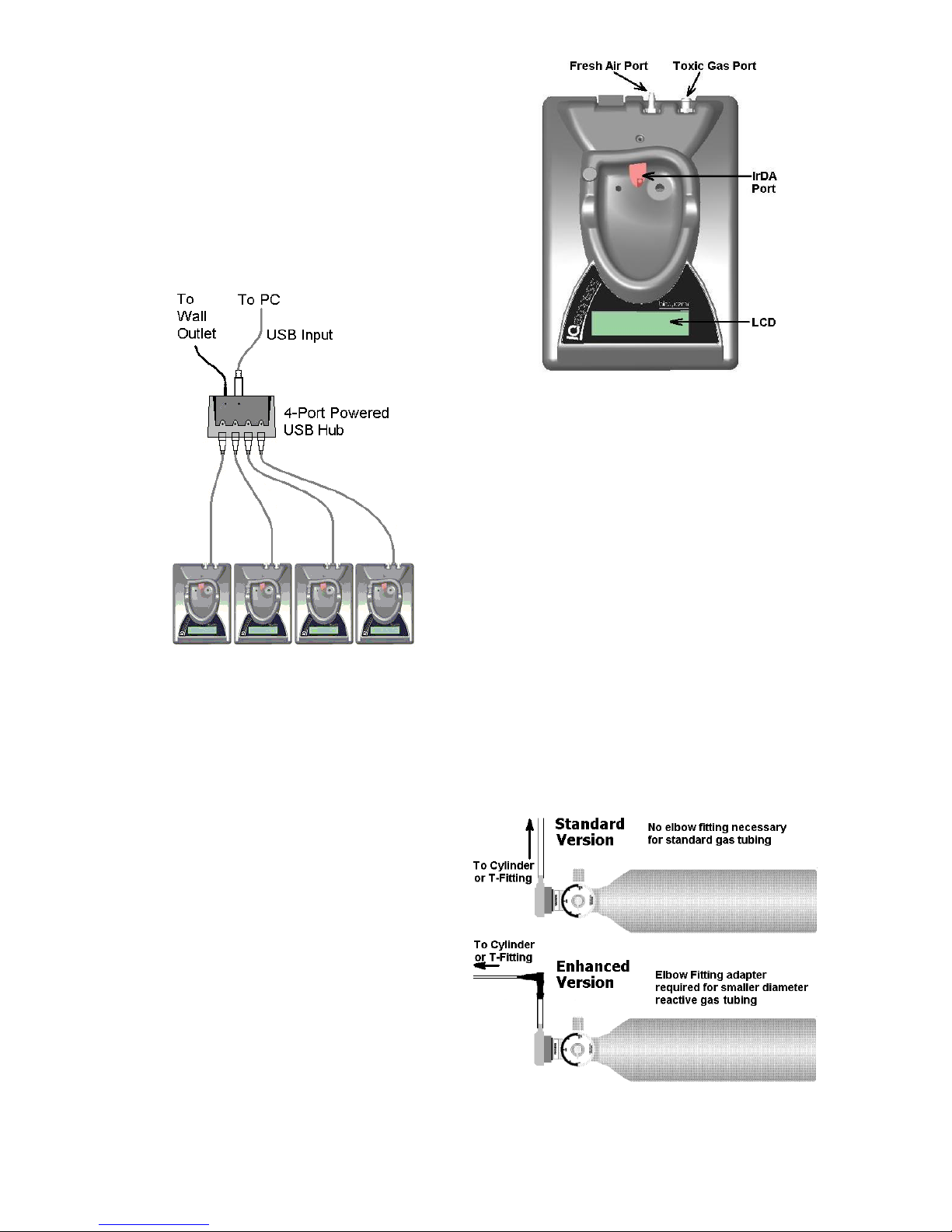
2.7 Connecting the Calibration
Gas Cylinder(s) to the
Dock(s)
Connection requirements for calibration gas
cylinders vary with how many docks will be
connected to the cylinder and whether the
calibration gas is considered reactive.
Enhanced versions of the IQ Express
include a tubing assembly that is suitable for
use with reactive gases.
Figure 2.7. IQ Express Gas Ports
For instructions on connecting the gas
cylinder to a single IQ Express dock
proceed to section 2.7.1.
For instructions on connecting the gas
cylinder to multiple IQ Express docks
proceed to section 2.7.2.
2.7.1 Single Cylinder to Single IQ
Express Dock
1. Insert the demand flow regulator into the
calibration gas cylinder.
2. Standard docks are delivered with a 24”
piece of tubing with a white quick
disconnect on one end. Enhanced
docks are delivered with a 24” piece of
tubing that meets a black elbow fitting
followed by a 1” piece of standard
tubing. Slide the open end of the tubing
assembly over the regulator. For
enhanced docks, slide the open end of
the 1” piece of tubing over the regulator.
Figure 2.7.1 Standard versus Enhanced
Setup for Regulator and Tubing

10
Note that the tubing assemblies for the
standard and the enhanced versions of
the IQ Express Docks are different. The
tubing assembly for the enhanced
versions includes a black elbow fitting
that should be located just above the
regulator.
3. Connect the end of the tubing with the
white quick disconnect fitting to the toxic
GAS port on the IQ Express Dock (see
figure 2.7 above for location of the GAS
port).
4. Proceed to section 2.7.3 for further
instructions concerning the fresh AIR
port.
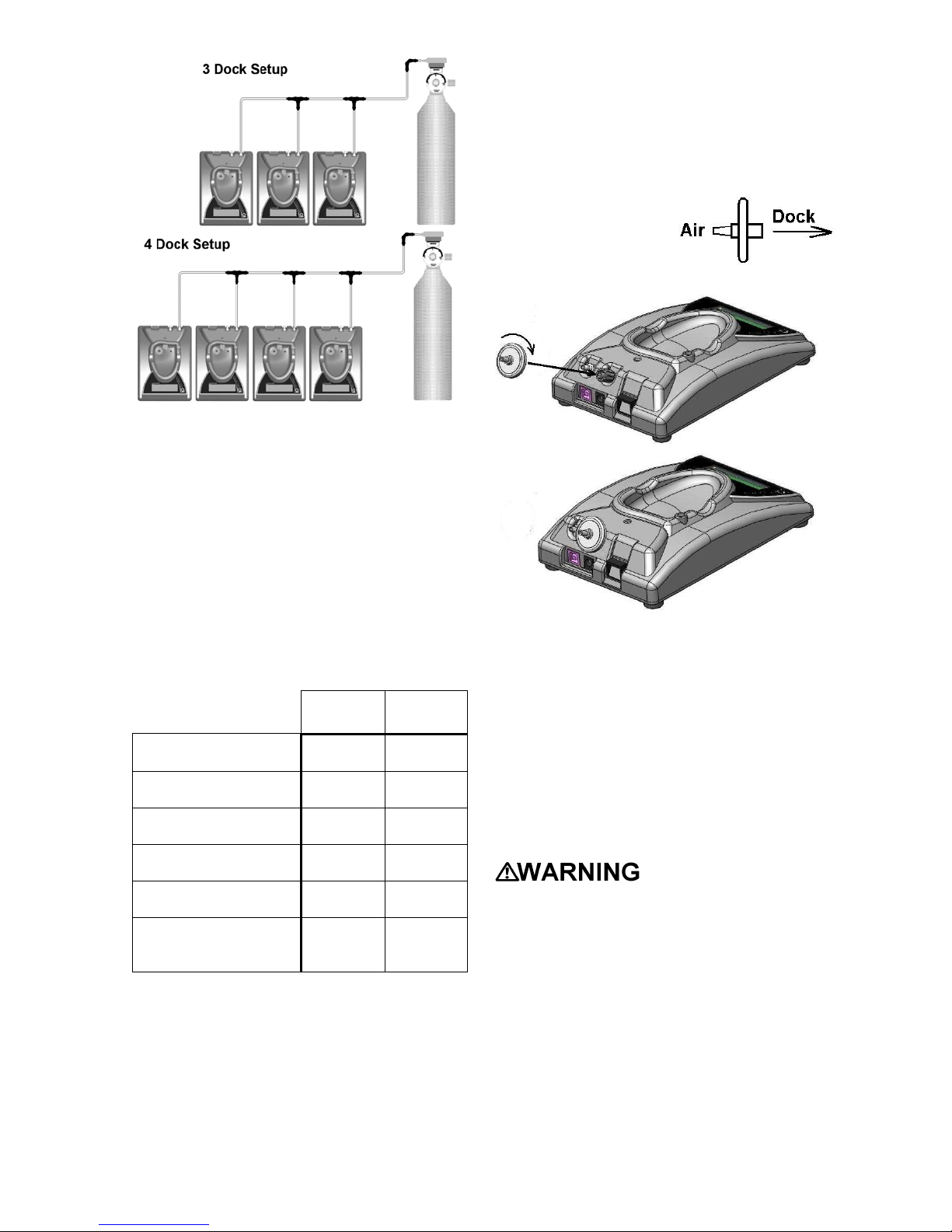
2.7.2 Single Cylinder to Multiple
Docks
When a series of IQ docks is connected to a
single cylinder of calibration gas, a manifold
is used to disperse the calibration gas from
the cylinder to the docks.
The manifold is part number 54-46-115 and
includes a detailed instruction sheet for its
use. The manifold comes with tubing and
fittings necessary for connecting up to 4
Express Docks to a single cylinder of
calibration gas.
Note: Do not exceed the output capacity
of your demand flow regulator. Each IQ
Express dock is able to draw calibration
gas at a maximum rate of 0.75
liters/minute. The demand flow regulator
supplied by Sperian Instrumentation
(part number 12-039) has a maximum
output capacity of 3 liters per minute, so
it can be used to calibrate up to 4 docks
simultaneously. Do not connect more
than 4 docks to a single cylinder of
calibration gas while using the 12-039
demand flow regulator.
The 54-46-115 manifold is comprised of:
(1) small black elbow fitting
(3) small black T-fittings
(2) pieces of gas tubing 5” long
(1) piece of gas tubing 10” long
(1) piece of gas tubing 1” long
54-46-0115 Manifold
1. Insert the Demand Flow Regulator into
the calibration gas cylinder.
2. Modify the tubing assembly as follows
depending on how many docks will be
connected. If 4 docks will be used, no
modifications are necessary. For 2 or 3
docks, begin by separating the tubing at
the location described below.
Once this is accomplished, set the two
parts aside. The section that will be
used is shown in the following images
(depending on the number of docks).
Manifold for two docks
Manifold for three docks
Manifold for four docks
3. Each dock is delivered with a 24” piece
of tubing with a white quick disconnect
fitting, which is normally used to connect
a single gas cylinder directly to a single
dock. Connect the white quick
disconnect fittings to the GAS ports on
the docks and connect the open ends to
the manifold’s open t-fittings. For
enhanced docks, remove the black
elbow fitting entirely from the 24” piece
of tubing and run the smaller diameter
tubing directly from the docks to the
open T-fittings.
At this point, tubing should run from each
dock’s GAS port to the t-fittings. There
should be no open T-fittings at this point in
the procedure, but there should be one
piece of open tubing on the elbow fitting.
4. Connect the open piece of tubing on the
elbow fitting to the Demand Flow
Regulator.
Final Appearance
11
Note: Tubing lengths in these images
are not to scale.
2.7.3 Fresh Air Port Instructions
The Fresh Air Port is used to draw the fresh
air sample into the dock for instrument
processing. Check valves and/or fresh air
filters are required depending on how fresh
air is delivered to the dock. See the chart
below for specific requirements for your
setup. The fresh air filter is placed on the
Air Port at the dock to protect the dock from
contaminants. Check valves are used to
ensure the purity of external fresh air
sources when more than one dock is used.
Air Filter
at Dock
Check
Valve(s)
Single Dock in Fresh
Air Yes N/A
Multiple Docks in
Fresh Air Yes N/A
Single Dock w/Zero
Air Cylinder No No
Multiple Docks
w/Zero Air Cylinder No Yes
Single Dock w/Sealed
Fresh Air Conduit Yes No
Multiple Docks w/
Sealed Fresh Air
Conduit
Yes Yes
Air Filter / Check Valve
Requirements Chart
Fresh Air Filter
Under normal circumstances, the IQ
Express Dock is located in a fresh air
environment and fresh air is drawn in from
the local environment. A filter is included
with the dock that is used to protect the
dock from contaminants that may
inadvertently enter the dock. The air filter
should be installed if the dock is drawing
fresh air from the immediate surroundings or
if it is drawing fresh air from an external
source via a sealed conduit. The fresh air
filter can be left off if the fresh air source is a
calibration cylinder.
Only one side of the
filter will screw into the
Air Port on the dock.
Providing Fresh Air in a
Contaminated Environment
If the IQ Express is to be located in a
potentially contaminated environment, fresh
air must be delivered to the Air Port on the
dock for use during instrument processing.
This can be accomplished either by using a
cylinder of “zero air” with a demand flow
regulator (option 1 below) or by plumbing
fresh air into the dock in a sealed conduit
from an outside location that has known
fresh air (option 2 below).
Performing the fresh
air calibration in a contaminated
atmosphere will lead to inaccurate and
potentially dangerous readings. Fresh
air containing 20.9% oxygen and no
contaminants must be provided to the IQ
Express Dock for instrument processing.
If fresh air is unavailable in the
immediate area, steps must be taken to
provide fresh air to the dock.
When a secondary fresh air source (either
gas cylinder or sealed conduit) is used with
two or more IQ Express Docks, a one-way
check valve must be placed in line between
the common section of the fresh air manifold

12
and each of the docks to ensure the purity
of the fresh air source. See the section
below titled “Fresh Air Manifold” for further
instructions.
Option 1: Using a Gas Cylinder to
Provide Fresh Air to the Dock
A calibration cylinder containing “zero air”,
which contains 20.9% oxygen and no
contaminants may be connected to the gas
port labeled “AIR” to provide fresh air to the
dock for calibration. The cylinder must be
equipped with a demand flow regulator.
The connection from the cylinder and
regulator to the dock may be made with
standard gas tubing.
For single docks, simply connect the “zero
air” cylinder and demand flow regulator to
the dock’s AIR port using standard gas
tubing. A check valve is not necessary
when a cylinder is used to provide fresh air
to a single dock. The fresh air filter is also
not required in this configuration.
For multiple dock setups (up to 4), a one-
way check valve must be placed in the line
between each T-fitting and dock to ensure
the purity of the fresh air source. See
“Multi-Dock Setups with Fresh Air Manifold”
below for further instructions. The fresh air
filter is not necessary when a gas cylinder is
used to provide fresh air to the dock(s).
Option 2: Using a Sealed Conduit to
Provide Fresh Air to the Dock
Fresh air may also be delivered to the dock
from a known fresh air source via a sealed
conduit that feeds directly from the source
into the AIR port on the dock.
For single docks, install the fresh air filter as
discussed above and simply plumb the fresh
air source directly into the dock’s AIR port.
For multiple dock setups in which fresh air is
provided to the dock via sealed conduit,
begin by installing the fresh air filter on each
dock. A one-way check valve must be
placed in the line between the t-fitting in the
fresh air manifold and each dock to ensure
the purity of the fresh air source. See
“Multi-Dock Setups with Fresh Air Manifold”
below for further instructions.
Multi-Dock Setups with Fresh Air
Manifold
For more information on this, see
Applications Note # AN20050722, which is
available at http://www.biosystems.com.
The 54-46-116 manifold is necessary for
use when more than one dock is to be used
with an external fresh air source, whether is
be a cylinder of “zero air” or a sealed
conduit to a fresh air source.
The 54-46-116 manifold is comprised of:
(3) small black T-fittings
(4) clear one-way check valves
(10) pieces of gas tubing 5” long
(1) piece of gas tubing 10” long
54-46-115 Tubing Assembly
1a. If the fresh air source is a calibration gas
cylinder, insert the Demand Flow
Regulator into the calibration gas
cylinder and proceed to step 2.
1b. If the fresh air source is a sealed conduit
from an external fresh air source, install
the fresh filter on each dock as
described above and proceed to step 2.
2. Modify the tubing assembly as follows
depending on how many docks will be
connected. If 4 docks will be used, no
modifications are necessary. For 2 or 3
docks, begin by separating the tubing at
the location described below.
Once this is accomplished, set the two
parts aside. The section that will be
used is shown in the following images
(depending on the number of docks).
Fresh Air Tubing for 2 Docks
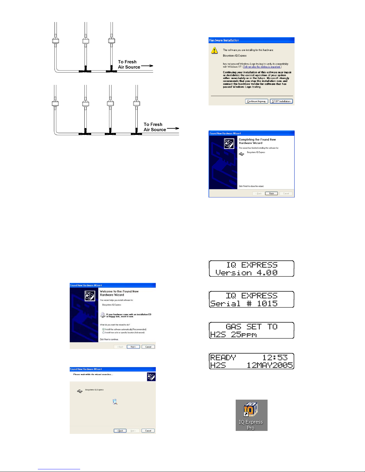
13
Fresh Air Tubing for 3 Docks
Fresh Air Tubing for 4 Docks
3. Connect the pieces of tubing above the
check valves to filter that was installed
on the dock in step 2.
At this point, the tubing assembly should be
connected to each dock’s AIR port.
4. Connect the only open piece of tubing
(below the black t-fittings) to the
demand flow regulator on the gas
cylinder or to the conduit for the external
source of fresh air.
2.8 Dock Setup
Once the software has been installed, and
the USB wire(s) is/are plugged into the PC,
the Found New Hardware Wizard screen
will be shown on the PC.
NOTE: These screens vary depending
on your PC’s operating system.
Click Next to continue. The Wizard will
proceed to search for the USB drivers.
If installing to XP, the following screen will
be shown and should be disregarded.
Click “Continue Anyway” (XP Only). The
software will notify you when the process is
complete.
Click “Finish”.
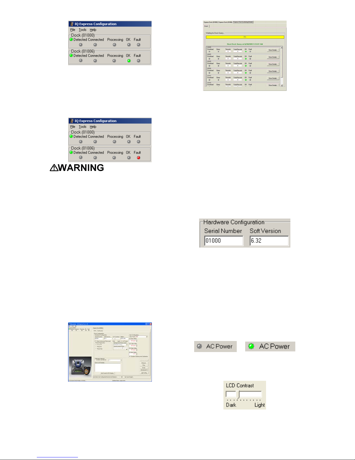
The IQ Express Dock will display its
software version number, serial number,
and the calibration gas type and expected
calibration gas concentration whenever it is
plugged in. The IQ Express is ready to go
once it displays “READY” with the gas type,
time and date.
↓
↓
↓
3. Software
To launch the IQ Express Software, click on
the IQ Express icon on your PC’s desktop.

14
Note: Do not launch the software until
the installation instructions in section 2.1
– 2.8 have been completed.
The software may also be launched by
accessing the program through the start
button and selecting Programs / Biosystems
/ IQ Express / IQ Express (unless another
location was specified during the
installation).
Once the IQ Express Software is launched,
the following screen will be shown.
The screen is divided into right and left
sides. The left side gives the status of the
docks that are currently installed and
recognized. At the top of the right side of
the screen there is a tab for each dock that
is currently installed and recognized. Within
each dock tab are two sub-tabs: one for
dock controls and one that shows the
calibration status and details for the
instrument that is currently in the dock.
3.1 Dock Status
3.1.1 Dock status LED
The status bars at the far left show the
status of the docks that are currently
registered on the PC.
Each dock that is currently connected to the
PC by either USB or by a “Live” Ethernet
connection will have a distinct status bar.
The green LED at the far left shows the
general status of the dock.
All docks that are connected via Ethernet
and are currently in “Listening Mode” are
given a single status bar.
For docks in Listening Mode, if a single fault
is detected on any of the docks, the dock
LED will turn grey and the Fault LED will
turn red.
Specific information for individual docks in
“Listening Mode” can be accessed via the
“Express Dock (Listening Mode) tab on the
right side on the screen. See section 3.2 for
more information.
3.1.2 Instrument status LEDs
When a detector is placed in the dock, the
indicator will change to reflect the new
status. Status changes are also be shown
on the dock’s LCD.
↓
Processing is shown in yellow.
If the dock is able to successfully complete
processing, OK will be shown in green.
15
If a fault is detected and the IQ Express
Dock is unable to complete the tests, the
red fault light will be lit on the screen.
Details of the fault will be listed in the input
box on the right side of the screen under the
instrument tab. See section 3.2.2 for
details.
Do not reinsert the
ToxiPro or ToxiLtd back into an IQ
Express Dock for at least 5 minutes after
it has been removed. Immediate
reinsertion of the ToxiPro or ToxiLtd into
an IQ Express Dock may lead to
inaccurate and potentially dangerous
readings.
3.2 Dock Controls and
Instrument Status
The right side of the screen contains
individual controls for each IQ Express Dock
that is connected by USB or by a “Live”
Ethernet connection. Each dock has its own
page, which can be accessed by clicking on
the appropriate tab at the top of the page.
Within each dock’s page are two sub-tabs.
One contains specific information on the
dock itself. The other displays information
on any instruments that are currently
recognized in the dock.
The last tab on the left accesses all of the
IQ Express Docks that are connected by
Ethernet and in “Listening Mode”.
3.2.1 Dock Configuration
Click on the Dock tab to access the dock
settings.
To change the configuration of the IQ
Express Dock that is currently connected to
the PC, click on the “Change Config” button
at the lower right of the screen. Once the
dock configuration is uploaded, the “Set
Config” button will be enabled. Once
changes are made, click on the “Set Config”
button to save the new settings.
Hardware Configuration
The hardware configuration section contains
the serial number and software version
number of the IQ Express Dock at the upper
left corner.
This information may not be arbitrarily
changed with the software. Software
updates will cause the software version to
change.
AC Power
The AC Power indicator is located directly
beneath the connection speed setting. If the
dock is being powered by the USB cable,
the AC Power will appear grey. When the
dock is being powered by an AC power
source, the AC Power indicator will appear
green.
or
LCD Contrast Control
At the right side of the Dock Configuration
box is the LCD Contast.
16
To darken or lighten the LCD on the IQ
Express Dock, move the slider as
appropriate.
Battery
The battery level shown on the dock tab is
for the internal battery in the IQ Express
Dock. This battery serves to keep the real
time clock accurate while the dock is
unplugged and should not be a concern to
the user unless the battery level drops
below 2.50 Volts.
Pump Diagnostics
Pump diagnostics are controlled through the
Pump Control section on the Dock Settings
page.
Click “Pump Gas” to draw span calibration
gas through the right gas port at the back of
the dock. Click “Pump Air” to draw the fresh
air sample through the left gas input port.
Either pump will run until “Pump Off” is
selected.
Audible Alarm Sensitivity Controls
The audible alarm sensitivity controls allow
the user to customize the audible alarm test
criteria.
The Background Noise Level adjustment
offers four levels of background noise
levels. For the best
results, select the one
that most closely
approximates the
background noise
level expected during
testing.
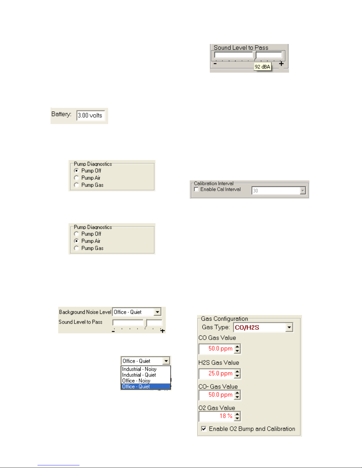
The Minimum Sound Level setting
determines the minimum amount of sound
required to pass the alarm test. The setting
is controlled by a slider. The higher the
setting, the louder the alarm will need to be
to pass the test. The sound level is given in
decibels when the cursor is placed over the
slider.
Calibration Interval
The Dock’s calibration interval settings are
controlled from the Dock Tab and are
located below the battery level and above
the LCD Display box. The dock’s calibration
interval is the maximum number of days that
the dock will allow to pass between
calibrations for any instrument that is placed
in the dock. If an instrument is placed in the
dock and the interval has been exceeded,
the dock will automatically initiate a full span
calibration of the instrument regardless of
the results of the bump test or the
instrument’s own calibration status.
To use the setting, click on Enable Cal
Interval and set the interval to the number of
days between calibrations. Note that this
setting overrides the instrument’s own
calibration due reminder and may cause
the instrument to undergo a full
calibration even when the instrument
itself is not due for calibration.
Gas Configuration
The calibration gas configuration settings
are located at the right side of the dock tab.
The Gas Type and Gas Value should be set
to exactly match the type and amount of
each component of the gas cylinder that is
connected to the inlet port on the dock.

17
To change the gas type, click on the down
arrow to the right of the gas setting and
select the new gas type.
Once the gas type is chosen, enter the
calibration gas composition, including the
values for any toxic gases in the cylinder in
terms of parts-per-million (ppm) and the
oxygen level in terms of percent volume
(%). To change a gas value use the arrows
to the right of the gas value input box to
increase or decrease the value until it
matches the value given on the gas
cylinder.
Since a common calibration gas mixture
includes CO and H2S, a CO/H2S option is
available that offers distinct settings for CO
and H2S. This allows the dock to process
CO, CO- and H2S units without changing the
gas setting.
Note: Due to cross-sensitivity issues,
CO+ detectors must be calibrated with
CO calibration gas only. A CO+ detector
placed in a dock that is configured for
CO/H2S will automatically fail to process.
The IQ System will automatically fail any
detector that is processed when the
calibration gas type fails to match the
sensor type.
Calibration values
shown in the Gas Value column must
match those appearing on the calibration
gas cylinder(s) that will be used to
calibrate the detector. Non-matching
calibration gas and calibration gas value
settings will lead to inaccurate and
potentially dangerous readings.
Special Instructions: Gas
Configuration, Oxygen Detectors
An oxygen detector can be processed by
the IQ Express in a fresh air atmosphere
without the use of calibration gas, but an
optional bump test is available to verify
oxygen sensor response. The O2 Bump
and Calibration is automatically enabled at
the factory. If the user wishes to bypass the
oxygen bump test, the O2 Bump and
Calibration option can be disabled by
deselecting the “Enable….: check box at the
bottom of the Gas Configuration settings. .
Each calibration gas type includes an
oxygen setting that should reflect the
amount of oxygen in the calibration gas
cylinder (typically 18%).
With the O2 Bump and Calibration option
enabled, when an oxygen detector is placed
in the dock, the system will proceed with an
oxygen bump test based on the O2gas
value that has been entered. If the bump
test fails, the dock will show a warning on
the screen that the instrument has failed the
test.
A special case exists when a cylinder of
0.0% oxygen calibration gas is connected to
the dock. If the O2 Gas Value is set to 0.0%
oxygen and the instrument fails the bump
test, it will automatically attempt a full zero
calibration at 0.0% oxygen.
For all other levels of calibration gas
(>0.0%), the oxygen bump test is the only
test available. The zero calibration of the
oxygen sensor is only available with
calibration gas containing 0.0% O2.
To disable the O2 Bump and Calibration
deselect the option.

18
Saving new settings
When all necessary changes have been
made, press the “Set Configuration” button
(in the lower right corner of the screen) to
upload the new settings to the IQ Express
Dock.
The software will notify you once the dock
configuration has been updated.
Dock LCD Display
At the lower left corner of the Dock status
tab is Dock LCD Display window. This is
most often used when a dock is controlled
remotely via Ethernet where the PC user is
unable to physically see the dock.
To view the dock’s Display, click on “Get
Current LCD Display”.
Ethernet Controls
For docks that are
connected by
Ethernet, there are
three additional
controls on the lower
right corner of the
display: Ethernet,
Ping and E-mail.
To view the Ethernet
settings, click on the
Ethernet button
To test the dock connection, press the Ping
button. A status window will be shown to
indicate whether the ping was successful or
not.
The dock’s e-mail settings are controlled
through the Database Manager Pro
program, but can be viewed by clicking on
the e-mail button. The e-mail status, IP
Address of the dock, recipient e-mail
address and text of the e-mail message are
shown.
To test the e-mail ability of the dock, press
the Test E-mail button at the lower left. An
e-mail will be generated and sent to the
recipient e-mail address that is listed.
Press OK to close the Email Setup window.
3.2.2 Instrument Tab
The ToxiPro/Ltd tab shows instrument
information for the detector that is currently
in the IQ Express Dock. The right side of
the tab is identical to the Dock Status tab
section discussed above. The blank space
at right shows is an output box that shows
detailed instrument information as it is
processed.

19
The output box is updated as the instrument
is processed. If any faults occur, the details
of the fault will be shown and a red fault light
will be shown. In the image below, a span
calibration failure is the cause of the fault.
If the datalogger has been downloaded, the
“View Session Data” control will appear on
the right. Click on “View Session Data” to
directly access individual session files for
the instrument. The session files can be
accessed using the BioTrak Program.
If the dock is currently empty, none of the
status indicators will be lit and the output
box will be blank.
3.3 Advanced Settings /
Passcode
The IQ Express Dock may be set to verify a
specific 4-digit passcode (PIN) in any
instrument that interfaces with the dock. If
the dock detects a PIN in the instrument that
matches its own PIN, it will process the
instrument. If the dock fails to detect a PIN,
or recognizes a non-matching PIN, it will not
process the instrument.
To use the passcode feature a PIN must be
entered into the IQ Express Software and
then uploaded to every instrument that will
interface with the dock. Each dock must
then be programmed with the same PIN and
set to check for the code in the instruments.
1. Verify that the ToxiPro and ToxiLtd
instruments have firmware version 6.3
or higher. Instrument firmware version
is shown in the start up screens for the
instrument.
If needed, new ToxiPro Firmware can
be downloaded at no charge from
Sperian Instrumentation’s download
website at
http://www.biodownloads.com. The
ToxiLtd will need to be returned to
Sperian Instrumentation for firmware
updates.
2. Verify that the IQ Express Dock contains
firmware version 4.23 or higher. New
dock firmware can also be downloaded
at no charge from Sperian
Instrumentation’s download website at
http://www.biodownloads.com.
3. Select the dock that will be used to write
the PIN (Personal Identification Number)
to the instrument. Connect the dock to
the PC either by USB port or by
Ethernet port. If using an Ethernet
connection, the Ethernet setting must be
configured to “Live”. If more than one
dock will be used to update the
instruments, perform steps 4-10 for
each dock.
4. Open the IQ Express software.
5. Click “Advanced” in the row of buttons
on the lower right. The software will
automatically show the Security Login
screen and prompt you for your user
name and password. If the “Advanced”
button is not shown, click on “Change
Config” first to access it.
6. Enter a valid User ID and Password.
The Access PIN settings will be shown:
Table of contents
Other GasTech Docking Station manuals


