GasTech IQ6 User manual
Reference
Manual
IQ6
Docking Station
for
PHD6
‘
Gastech
24 Baretta Rd
Wangara Western Australia 6065
Tel 1800 999 902
Fax 1800 999 903
http://www.gastech.com
Contact Information

1
THE IQ6 DOCKING STATION IS DESIGNED TO INTERFACE WITH PHD6 GAS
DETECTORS.
SPERIAN GAS DETECTORS HAVE BEEN DESIGNED FOR THE DETECTION
OF DEFICIENCIES OF OXYGEN, ACCUMULATIONS OF FLAMMABLE GASES
AND VAPORS AND ACCUMULATIONS OF TOXIC VAPORS.
IN ORDER TO ENSURE THAT THE USER IS PROPERLY WARNED OF
POTENTIALLY DANGEROUS ATMOSPHERIC CONDITIONS, IT IS ESSENTIAL
THAT THE INSTRUCTIONS IN THIS MANUAL AND THE OPERATIONS
AND/OR REFERENCE MANUAL(S) FOR THE GAS DETECTOR(S) BE READ,
FULLY UNDERSTOOD, AND FOLLOWED.
THIS MANUAL IS NOT INTENDED TO REPLACE THE OPERATIONS AND/OR
REFERENCE MANUALS FOR THE GAS DETECTOR. THIS MANUAL IS ONLY
DESIGNED TO AID IN THE INSTALLATION AND OPERATION OF THE IQ
EXPRESS SYSTEM AND SHOULD BE USED IN CONJUNCTION WITH THE
INSTRUMENT REFERENCE OR OPERATIONS MANUAL AT ALL TIMES.
IQ6 Docking Station
Reference Manual
Part Number 13-324
Version 1.01
Copyright 2008
by
Sperian Protection Instrumentation, LLC
Middletown, Connecticut 06457
All rights reserved.
No page or part of this operation manual may be reproduced in
any form without written permission of the copyright owner
shown above.
Sperian Instrumentation reserves the right to correct
typographical errors.

2
Table of Contents
Warnings and Cautions 3
A. Signal Words 3
1.Overview 4
1.1 Tests and record keeping 4
1.2 PC Connection 4
1.2.1 USB Connection 4
1.2.2 Ethernet Connection and E-mail 4
1.3 PC Requirements 4
1.4 Power Requirements 5
1.5 Sensor compatibility 5
1.6 Calibration Gas Cylinder Regulator Requirement 5
1.7 Dock Location 5
1.8 Delivery 5
1.9 Battery Charging 5
2.Installation 5
2.1 Installation Overview 5
2.2 IQ Administrator Pro and PostgreSQL Database Server Installation 6
2.3 IQ Database Manager Software Installation 6
2.4 IQ6 PC Software Installation 6
2.5 Install IQ Administrator Pro and PostgreSQL database. 7
2.6 Power and Connectivity 8
2.6.1 USB Connection 8
PC – Single Dock via USB 8
PC – Multi Dock via USB 8
2.6.2 Ethernet Connection 8
2.6.3 Power 8
2.7 Connecting the Calibration Gas Cylinder to the Dock(s) 8
2.7.1 Single Cylinder to Single Dock 8
2.7.2 Multiple Cylinders to Single Dock 9
2.7.3 Single Cylinder to Multiple Docks 9
2.7.4 Multiple Cylinders to Multiple Docks 10
2.7.5 Fresh Air Port Instructions 10
2.8 Initial PC- Dock Connection 10
2.8.1 PC screens 10
2.8.2 Dock screens 11
3.Software 11
3.1 Dock Status (USB Connection) 11
3.2 Dock Controls and Instrument Status 12
3.2.1 Dock Configuration 12
Hardware Configuration 13
Connection Speed 13
Audible Alarm Sensitivity Controls 13
AC Power 13
Pump Diagnostics 13
LCD Contrast Control 13
Status After Test 14
Battery 14
Calibration Interval 14
Gas Configuration 14

3
Optimize O2 Bump Test 15
Saving new settings 15
Dock LCD Display 15
Ethernet Controls 16
3.2.2 PHD6 Tab 16
3.2.2.1 Instrument Tab 17
General 17
Calibration/Bump Testing 17
Features 17
Service/Security Tab 17
Custom Screens 17
3.2.2.2 Sensors Tabs 17
3.3 Advanced Settings / Passcode 17
4.Dock Use 19
4.1 Test Sequence 20
4.2 Loss of IrDA Connection 20
4.3 Test Failures 20
4.3.1 No gas detected 21
4.3.2 Span calibration failure 21
4.3.3 Alarm test failure 21
4.3.4 PC Aborted Test 21
4.4 Instrument Charging 21
4.5 Cleaning the IQ6 Dock 21
5.Menu Items 21
5.1 File Menu 21
5.2 Tools Menu 21
5.2.1 Dock 22
5.2.2 PHD6 22
5.2.3 Certificates 22
5.2.4 Session Downloading 23
5.3 Help Menu 23
6.Software Upgrades 23
Appendix A: USB Architecture with Network Access 24
Appendix A: Calibration Frequency 25
Sperian Instrumentation Warranty Gas Detection Products 26
Warnings and Cautions
A. Signal Words
The following signal words, as defined by ANSI Z535.4-1998, are used in the IQ Express
Reference Manual.
indicates an imminently hazardous situation which, if not
avoided, will result in death or serious injury.
indicates a potentially hazardous situation which, if not
avoided, could result in death or serious injury.
indicates a potentially hazardous situation, which if not
avoided, may result in moderate or minor injury.
CAUTION used without the safety alert symbol indicates a potentially
hazardous situation which, if not avoided, may result in property damage.

4
1. Overview
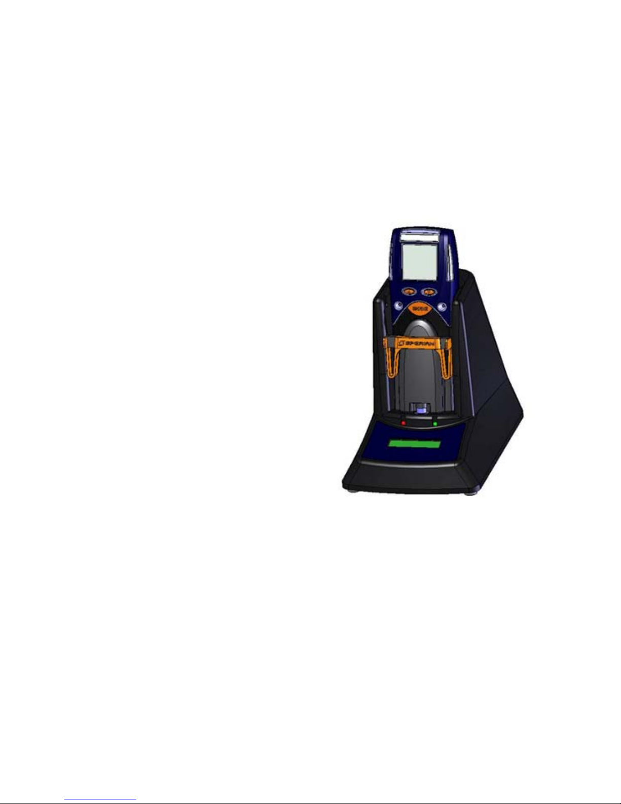
The IQ6 Docking Station is an automatic
calibration station for use with the
Sperian PHD6 Gas Detectors. The IQ6
Docking Station automatically performs
up to eight critical tests including sensor
identification, instrument performance,
bump and alarm tests and record-
keeping procedures in 1 minute (for
common configurations). The station
also retains a historical record of testing
and instrument maintenance in the
system's onboard memory.
The IQ6 Dock may be operated as a
stand-alone calibration station, or may be
connected to a PC via USB cable or
Ethernet for increased control over
system operations.
When the Dock is operated without a PC
interface, it will operate with the last set
of calibration gas settings that were
uploaded into the instrument.
Unless otherwise specified at the time of
purchase, all IQ6 Docks are shipped
from Sperian Instrumentation with
standard Sperian calibration gas settings.
In the event that the dock is to be used
as a stand-alone calibration station with
non-standard alarm settings, the dock
must be reprogrammed with the IQ6
Software.
The IQ Express Configuration Software
must be loaded onto the PC prior to
completing the USB connection.
Note: Do not connect the IQ6 Dock to
the PC until the software has been
installed.
1.1 Tests and record keeping
The IQ6 Docking Station automatically
performs the following procedures
whenever an instrument is placed in the
dock.
Instrument identification
Battery test
Audible alarm test
Visual alarm test
Vibrating alarm test (if applicable)
Fresh air calibration
Bump test
Record-keeping
Datalogger and Eventlogger
download (Dock must be connected
to PC)
In the event that an instrument fails the
bump test, or if the instrument’s
calibration due date has passed, the IQ6
Dock will automatically proceed to a full
calibration without further intervention
from the user.
If the instrument fails any of the tests
listed above, the IQ6 Dock will notify the
user through the display on the dock, and
through the PC if the dock is connected
to a computer and the software is
running.
Results of tests and calibration attempts
are stored in the dock and uploaded to
the PC if the software has been loaded
and the USB connection is active.
1.2 PC Connection
PC Software must be installed prior to
connecting the IQ6 Dock to the PC. An
overview of the installation procedure is
given below in section 2.1.
1.2.1 USB Connection
Every IQ6 Dock can be connected to the
PC via the PC’s USB port.
Note: USB cable length from PC to
dock may not exceed 10 feet.
1.2.2 Ethernet Connection and E-mail
IQ6 Dock s with the Ethernet upgrade
may be connected to the PC via USB or
via a network. For Ethernet Connection
instructions, follow the directions given in
the IQ Express Ethernet Instructions
booklet.
Docks that are connected by Ethernet
have additional controls at the PC to ping
the dock, to view the Ethernet settings
and to view and test the e-mail system.
E-mail may be sent to a single e-mail
address when a fault is detected at the
dock, but for no other reason. The dock
must be connected to a network via
Ethernet for the e-mail function to work.
E-mail capability is controlled entirely
through the IQ Database Manager Pro
program. For more information on the e-
mail function see Ethernet Controls in
section 3.2.1 below or the IQ Database
Manager Pro manual.
1.3 PC Requirements
Pentium II Processor 400MHz or
better or equivalent.
128MB RAM.
Windows 98*/2000**/XP

5
30MB hard drive disk space.
USB Port
*Sperian Instrumentation discourages
multiple IQ Express Dock setups with
PC’s running Windows 98.
**Service Pack 3 for Windows 2000 is
highly recommended.
1.4 Power Requirements
The IQ6 Dock must be plugged in to an
appropriate electrical outlet using the
power supply / wall cube that was
included with the dock at the time of
purchase.
The IQ6 Dock is delivered with an
appropriate power supply for the shipping
destination.
100-120 VAC, 60Hz, 9A
200-240 VAC, 50Hz, 4.5A
If the power supply includes a voltage
input selector switch, be sure to set the
switch to the appropriate voltage for your
electrical supply.
Power and Connectivity are discussed
in greater detail in section 2.3.
1.5 Sensor compatibility
The IQ6 Dock is capable of processing
instruments containing any of the
sensors that are available in the PHD6
except the ClO2sensor, which requires a
chlorine dioxide generator for calibration.
1.6 Calibration Gas Cylinder
Regulator Requirement
A demand-flow regulator must be used
with the IQ Express.
1.7 Dock Location
The IQ6 Dock should be located in an
area that is not exposed to direct
sunlight.
1.8 Delivery
Each IQ6 Docking Station is delivered
with the following items:
IQ6 Docking Station.
IQ6 Configuration Disc with IQ6 Pro
Software, IQ Database Manager Pro
Software and PostgreSQL Database
Server Software.
USB Cable.
Power Supply.
2’ piece of calibration gas tubing with
pre-installed white quick disconnect
fitting.
1.9 Battery Charging
Rechargeable versions of the PHD6 can
be charged in the IQ6 Dock. See section
4.4 for more details.
2. Installation
The IQ6 Docking Station must be
configured with a PC prior to use. Once
it has been configured, it may be used as
a stand-alone calibration station without
a PC connection, or connected to a PC
via USB or Ethernet (If so equipped) for
increased control over system
operations.
Unless otherwise specified at the time of
purchase, all IQ6 Dock s are shipped
from Sperian Instrumentation configured
with standard calibration gas settings.
Whenever the user chooses to activate
the IQ6 without an active PC connection,
the dock will operate with the last set of
calibration gas settings that were
uploaded into the instrument.
Note: Do not connect the IQ6 to the
PC until all three items on the IQ6
Installation Disc have been installed.
2.1 Installation Overview
A number of software programs and a
PostgreSQL Database Server must be
installed to control the IQ6.
1. Install the PostGreSQL Database
Server and the IQ Administrator Pro
Program as described in the IQ
Administrator Pro Reference Manual.
2. Install the IQ Database Manager Pro
program as described in the IQ
Database Manager Pro Reference
Manual.
3. Install the IQ6 PC Software as
described below in section 2.4.
4. Create a default PostgreSQL
database as described in section 6 of
the IQ Administrator Pro Reference
Manual.
5. If connecting the dock to the PC via
USB, follow the instructions in section
2.6. If connecting the dock via
Ethernet, follow the Ethernet
Instructions booklet.
6. Follow the instructions in section 2.7
for connecting the calibration gas
cylinders.
7. For docks that will be connected
permanently by USB port, configure
6
the docks by connecting them to the
PC’s USB port. If the instrument is to
be connected via Ethernet, follow the
Ethernet Instructions that came with
the dock.
2.2 IQ Administrator Pro and
PostgreSQL Database Server
Installation
The IQ Administrator Pro Program is
contained on the IQ Express Installation
Disk. Place the disk in your PC’s CD tray
and follow the installation instructions
given in the IQ Administrator Pro
Reference Manual that is included with
the IQ Express.
2.3 IQ Database Manager
Software Installation
The Database Manager Pro Program is
contained on the IQ Express Installation
Disk. Place the disk in your PC’s CD tray
and follow the installation instructions
given in the IQ Database Manager
Software manual that is included with the
IQ Express.
2.4 IQ6 PC Software Installation
The PostgreSQL Database Server and
IQ Database Manager Pro Programs
should be installed before proceeding to
step 1.
Note: Screens shown below may be
slightly different depending on your
PC’s operating system.
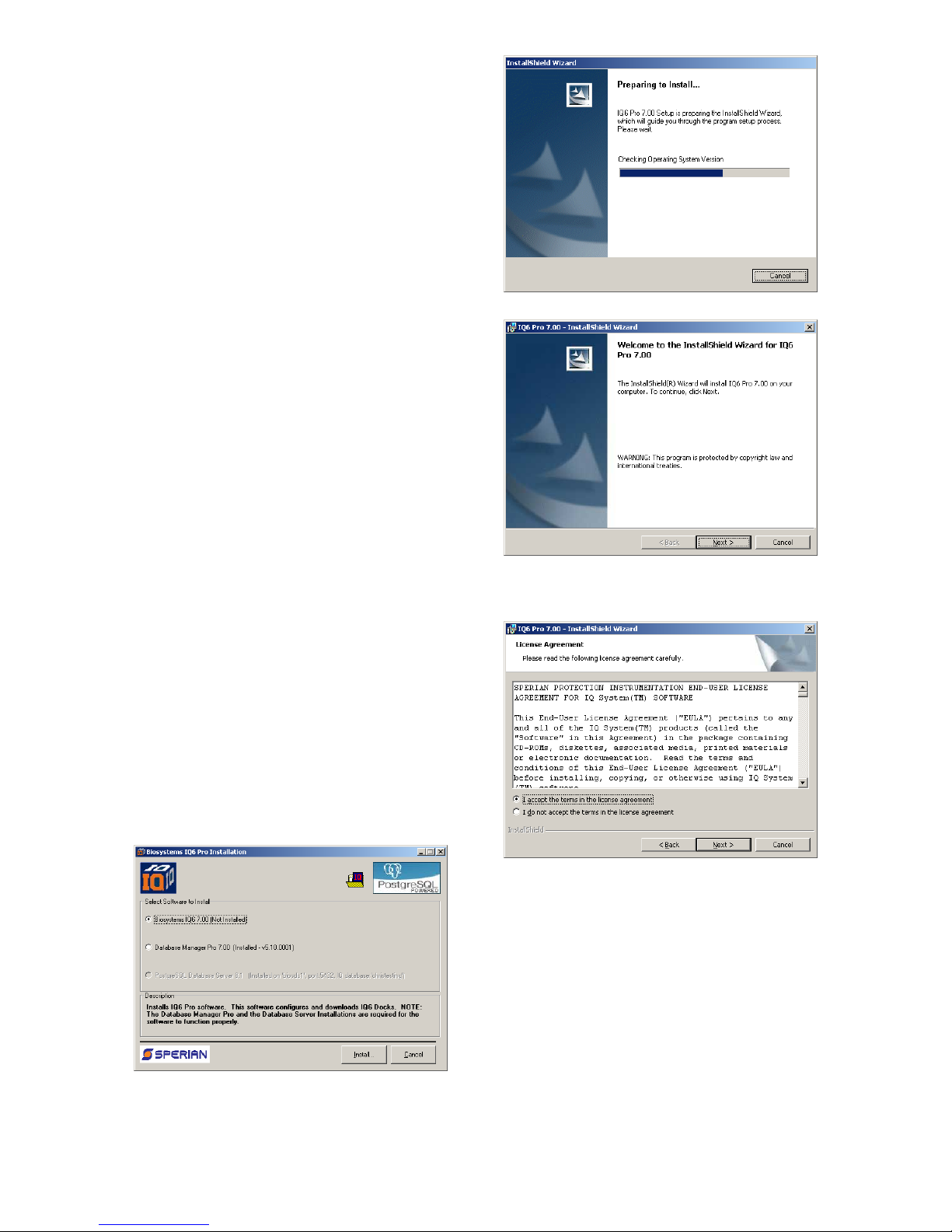
1. The Software Installation screen
should come up automatically once
the installation of Database Manager
is complete. If this screen does not
come up, access the CD drive using
Windows Explorer.
2. Select “Biosystems IQ6” and click
“Install”. The InstallShield Wizard will
begin the installation.
3. Click “Next” to continue with the
installation. The Licensing
Agreement screen will be shown.
4. If you accept the terms of the License
Agreement, click “I accept.....” and
then click “Next” to continue. The
upgrade information and PC
requirements will be shown.
7
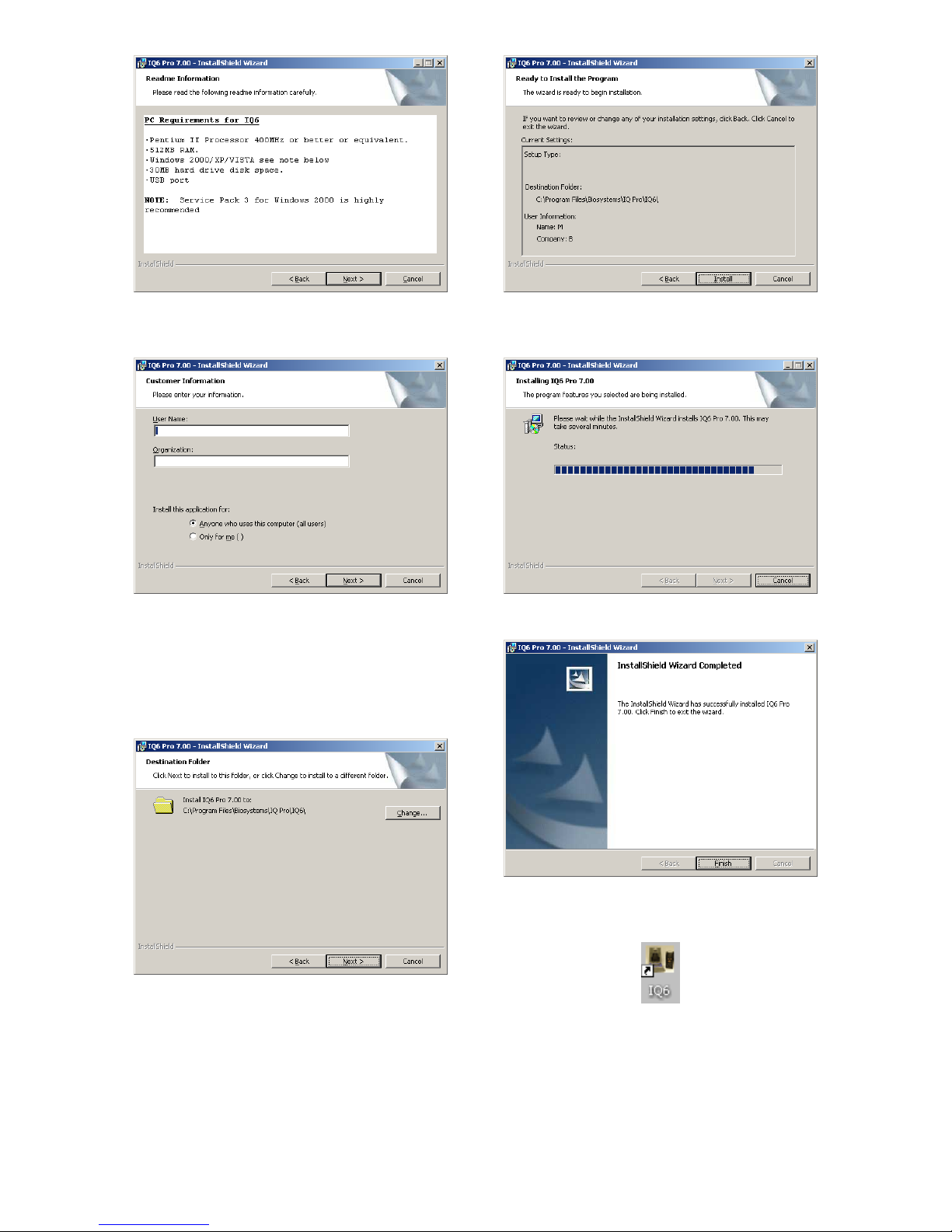
5. Click “Next” to continue. The
Customer Information screen will be
shown.
6. Enter the name of the user and the
name of the organization. Then
select whether this application may
be used by “Anyone who uses this
computer” or “Only for me”. Then
click “Next. The destination folder
screen will be shown.
7. To install IQ Express in the default
directory at “C:\Program Files \
Biosystems \ IQ Pro \ IQ6 \” click
“Next”. To install the files to another
directory, click “Browse” and use
Windows Explorer to specify the new
location. Click “Next” once this is
accomplished. The following screen
will then be shown.
8. Click “Next” to continue. The status
of the file decompression will be
shown.
Once the installation is complete, the
following screen will be shown:
9. Click Finish to conclude the
installation. The IQ Express logo will
appear on your desktop.
Note: Do not launch the IQ6 Software
again until the instructions in sections
2.5 – 2.8 below have been completed.
2.5 Install IQ Administrator Pro
and PostgreSQL database.
Proceed to the IQ Administrator Pro
Reference Manual section 6 and follow
8
the instructions to create and specify the
PostgreSQL database.
2.6 Power and Connectivity
This section covers providing power to
the IQ Express Docks and connecting
them to your PC.
Unlike certain configurations of other
Biosystems IQ Docking Stations, the IQ6
Dock must be plugged into an AC power
source with the power supply that was
provided with the dock.
Note: The change the calibration gas
settings, the dock will need to be
connected to the PC. Once the settings
have been changed, it can be
disconnected and used as a standalone
calibration station again.
If you plan to connect the dock to a PC
via either USB or Ethernet, first complete
the PC-dock connection, then plug the
dock into a wall outlet with the wall cube
provided with the dock.
2.6.1 USB Connection
Single or multiple IQ6 Docks may be
connected to a PC via a standard USB
cable.
Note: USB cable length from PC to
dock may not exceed 10 feet in either
single dock or multi dock setups.
PC – Single Dock via USB
For single dock setups that will be run
from the PC via USB, simply connect the
dock to the PC with the USB cable that
was included with the dock and proceed
to section 2.7 for instructions concerning
calibration gas.
PC – Multi Dock via USB
For multi-dock configurations that will be
connected via USB, Sperian
recommends the use of a USB hub,
which allows a single USB port on the
PC to control multiple USB devices
directly through a standard USB cable.
If you prefer to not use a USB hub, and
have enough open USB ports on your
PC to connect each of the docks directly
to its own USB Port, you may connect
each dock directly to the PC. Most users
decide against this option either because
their PC doesn’t have enough USB ports,
or because it is an inappropriate use of
their PC’s system resources.
2.6.2 Ethernet Connection
IQ Express Docks with the Ethernet
option are shipped with an Ethernet
Instructions booklet. Proceed to the
Ethernet Instructions booklet if you are
planning to connect the dock to the PC
via Ethernet. Once the instructions in the
booklet have been followed and the IQ
Express Dock is connected, return to
section 2.7 for calibration gas cylinder
connection instructions.
2.6.3 Power
The IQ6 Dock must be plugged in to a
standard AC wall outlet regardless of the
status of the PC connection.
2.7 Connecting the Calibration
Gas Cylinder to the Dock(s)
Connection requirements for calibration
gas cylinders vary with how many docks
will be connected to the cylinder.
Note: The maximum length of tubing
between the calibration cylinder and
any IQ6 Express Dock is 10 feet.
For instructions on connecting the gas
cylinder to a single dock proceed to
section 2.7.1.
For instructions on connecting the gas
cylinder to multiple docks proceed to
section 2.7.3.
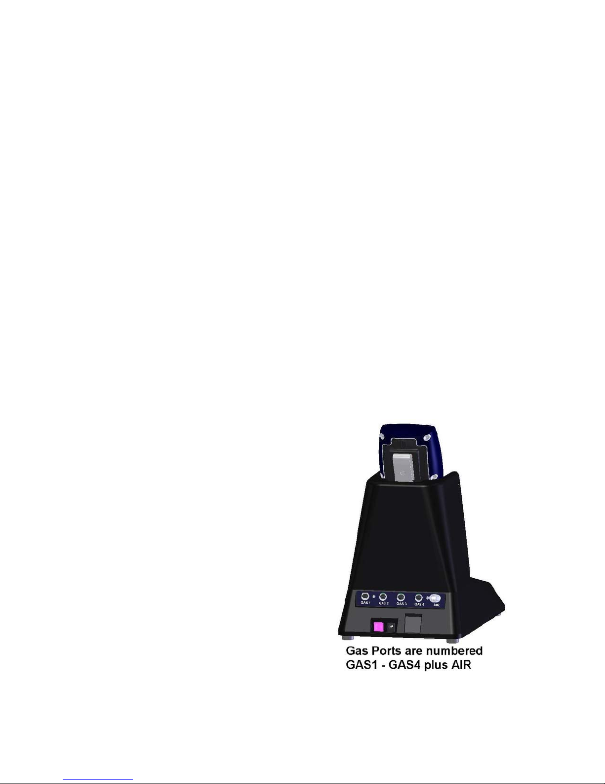
Figure 2.7: Rear of IQ6 Dock
2.7.1 Single Cylinder to Single Dock
1. Insert the demand flow regulator into
the calibration gas cylinder.
9
2. Slide the open end of the tubing
assembly over the regulator.
3. Connect the end of the tubing with
the white quick disconnect fitting to
the GAS1 port on the dock (see
figure 2.7).
4. Proceed to section 2.7.5 for further
instructions concerning the fresh AIR
port.
2.7.2 Multiple Cylinders to Single Dock
The PHD6 includes 4 calibration gas inlet
ports to provide calibration flexibility for
gas detection programs that include
many detectors with a wide variety of
sensors.
To connect more than one cylinder to the
IQ6 Dock, follow the instructions in
section 2.7.1 and repeat as many times
as necessary to connect cylinders to the
GAS2, GAS3 and GAS4 inlet ports on
the back of the dock.
Note: The IQ6 Dock Software must be
programmed with port-by-port details
of the gases used. See section 3.2.1
below.
2.7.3 Single Cylinder to Multiple Docks
When multiple IQ docks are connected to
a single cylinder of calibration gas, a
manifold is used to disperse the
calibration gas from the cylinder to the
docks.
The manifold is Sperian part number 54-
46-115 and includes a detailed
instruction sheet for its use. The
manifold comes with tubing and fittings
necessary for connecting up to 4 docks
to a single cylinder of calibration gas.
Note: Do not exceed the output
capacity of your demand flow
regulator. Each IQ Express dock is
able to draw calibration gas at a
maximum rate of 0.75 liters/minute.
The demand flow regulator supplied
by Sperian Instrumentation (part
number 12-039) has a maximum
output capacity of 3 liters per minute,
so it can be used to calibrate up to 4
docks simultaneously. Do not
connect more than 4 docks to a single
cylinder of calibration gas while using
the 12-039 demand flow regulator.
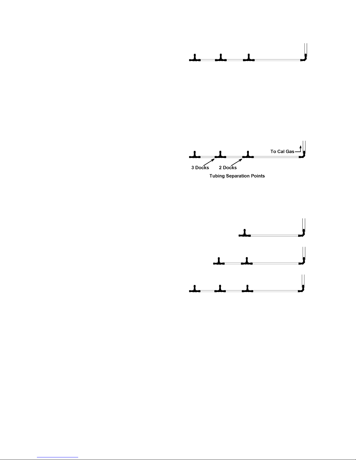
The 54-46-115 manifold is comprised of:
(1) small black elbow fitting
(3) small black T-fittings
(2) pieces of gas tubing 5” long
(1) piece of gas tubing 10” long
(1) piece of gas tubing 1” long
54-46-0115 Manifold
1. Insert the Demand Flow Regulator
into the calibration gas cylinder.
2. Modify the tubing assembly as
follows depending on how many
docks will be connected. If 4 docks
will be used, no modifications are
necessary. For 2 or 3 docks, begin
by separating the tubing at the
location described below.
Once this is accomplished, set the
two parts aside. The section that will
be used is shown in the following
images (depending on the number of
docks).
Manifold for two docks
Manifold for three docks
Manifold for four docks
3. Each dock is delivered with a 24”
piece of tubing with a white quick
disconnect fitting, which is normally
used to connect a single gas cylinder
directly to a single dock. Connect the
white quick disconnect fittings to the
GAS ports on the docks and connect
the open ends to the manifold’s open
t-fittings.
At this point, tubing should run from each
dock’s GAS port to the t-fittings. There
should be no open T-fittings in the
procedure, but there should be one piece
of open tubing on the elbow fitting.
4. Connect the open piece of tubing on
the elbow fitting to the Demand Flow
Regulator.
10
2.7.4 Multiple Cylinders to Multiple
Docks
The PHD6 includes 4 calibration gas inlet
ports to provide calibration flexibility for
gas detection programs that include
many detectors with a wide variety of
sensors.
To connect more than one cylinder to
more than one IQ6 Dock, follow the
instructions in section 2.7.3 and repeat
as many times as necessary to connect
cylinders to the GAS2, GAS3 and GAS4
inlet ports on the back of the dock.
Note: The IQ6 Dock Software must be
programmed with port-by-port details
of the gases used. See section 3.2.1
below.
2.7.5 Fresh Air Port Instructions
The Fresh Air Port is used to draw the
fresh air sample into the dock. IQ6
Docks are shipped equipped with an
external filter that is connected to the
Fresh Air Port via a small section of
tubing to ensure that no particulate
contaminants are introduced to the dock
or the detector.
If you expect to locate the IQ6 Dock in a
potentially contaminated environment,
remove the filter and connect a cylinder
containing “zero air”, which contains
20.9% oxygen and no contaminants, to
the left gas input port (labeled “AIR”).
The zero air cylinder must be equipped
with a demand flow regulator. The
connection from the demand flow
regulator to the dock may be made with
standard tubing.
Performing the
fresh air calibration in a contaminated
atmosphere will lead to inaccurate
and potentially dangerous readings.
The IQ6 Dock must be located in a
fresh air environment containing
20.9% oxygen and no toxic gases
during calibration. If fresh air is
unavailable, a cylinder of “zero air”
containing 20.9% oxygen and 0 PPM
toxic gases must be connected to the
fresh air port with a demand flow
regulator and a piece of tubing
whenever an instrument is in the IQ6
Dock .
2.8 Initial PC- Dock Connection
Once the software has been installed,
and the USB wire(s) is/are plugged into
the USB port, the Found New Hardware
Wizard screen will be shown on the PC
and a number of messages will be shown
on the IQ6 Dock .
2.8.1 PC screens
The Found New Hardware screens will
be shown whenever a dock is plugged
into a new USB port, and also whenever
a dock is plugged into a USB Port that
was most recently used for a different
device.
NOTE: These screens will vary
depending on your PC’s operating
system.
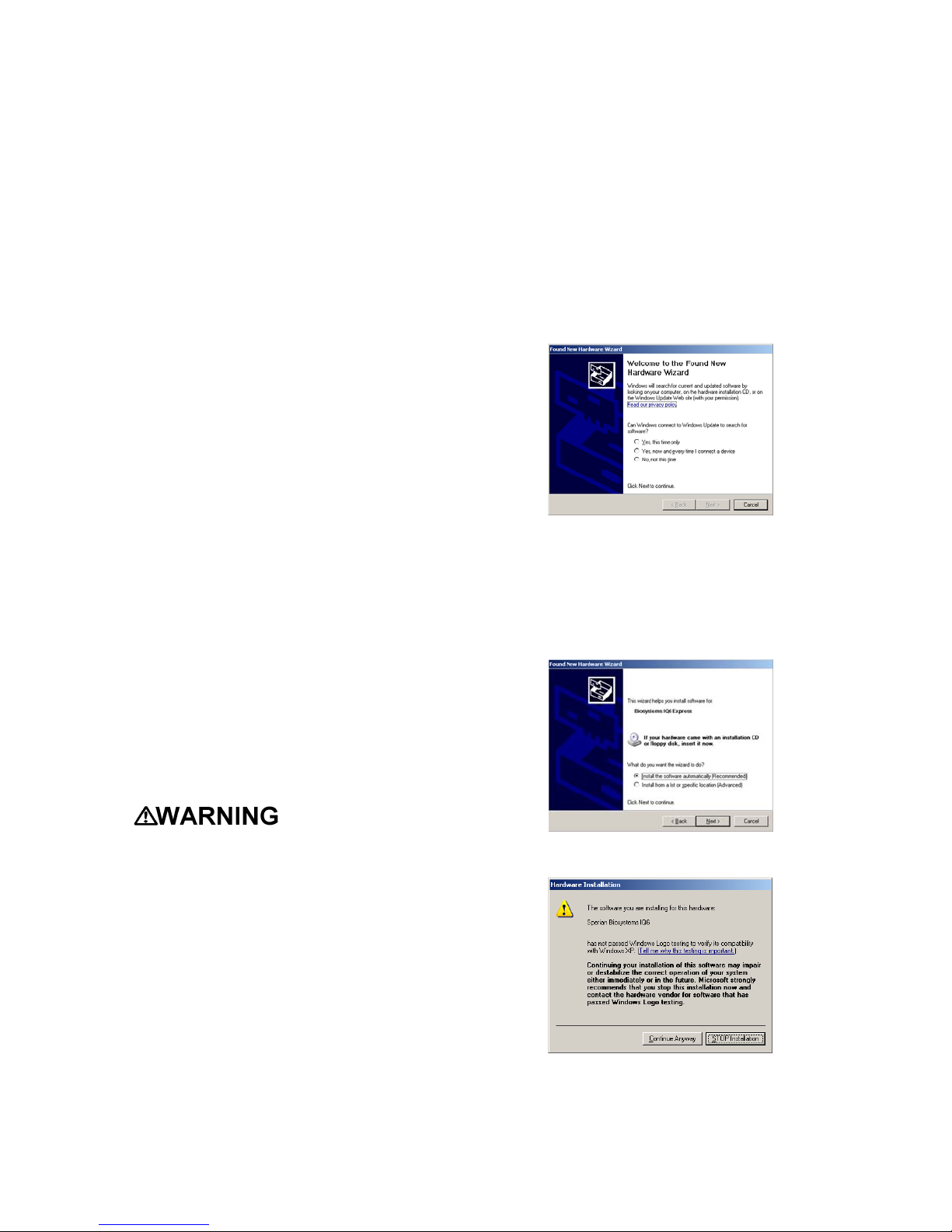
The software will prompt to ask if it
should connect to Windows Update to
search for software. Make a selection
based on how you would like to use your
PC’s operating system and click Next to
continue. The Wizard will proceed to
search for the USB drivers.
Select “Install the software automatically”
and click “Next”.
In Windows XP, a warning screen will be
shown stating that IQ6 Software has not
passed Windows Logo testing. Click
“Continue Anyway” (XP Only). The
installation will then continue.
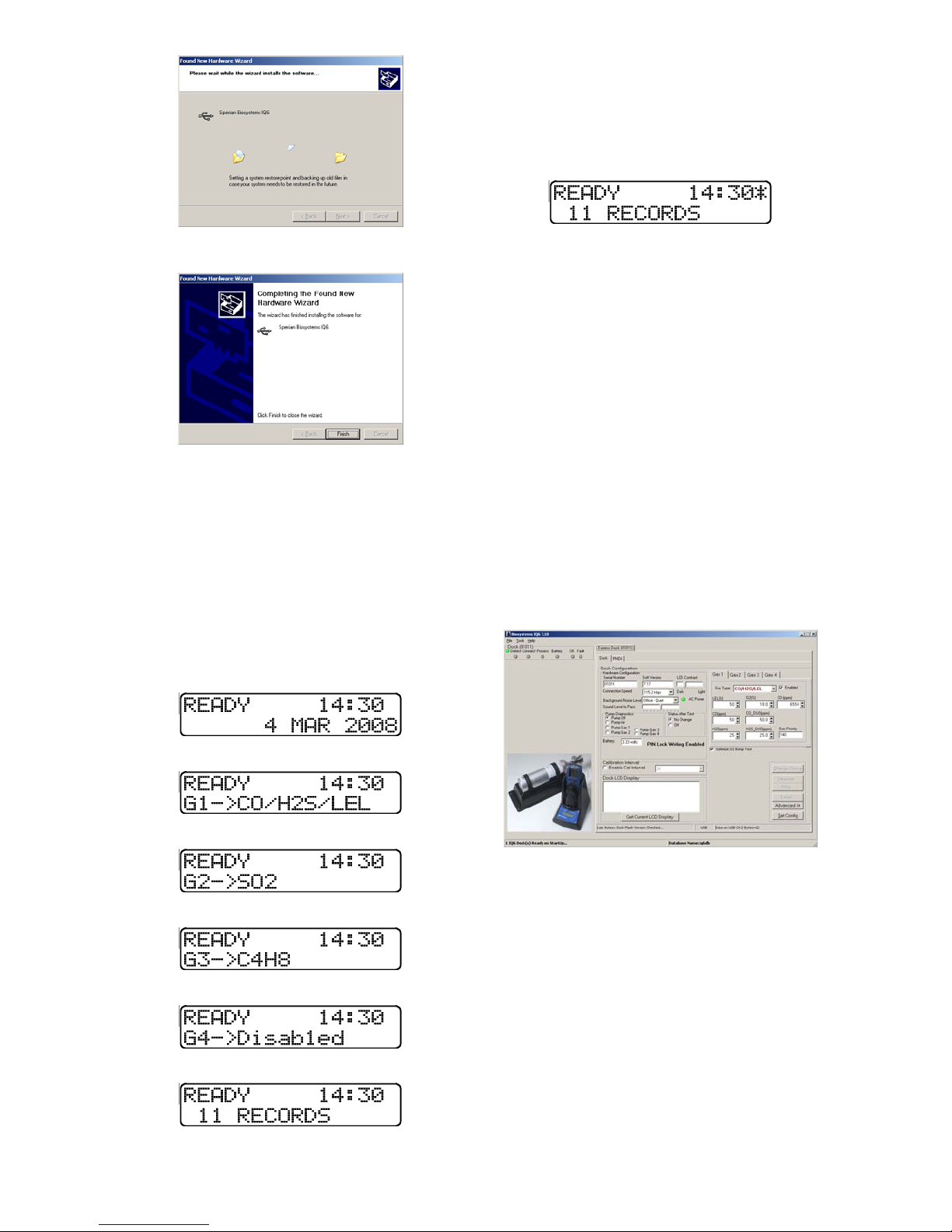
11
The software will notify you when the
process is complete.
Click “Finish”.
2.8.2 Dock screens
Once the connection is made, the dock
will display its software version number,
serial number, and the calibration gas
type and expected calibration gas
concentration whenever it is plugged in.
The IQ6 Dock is ready to go once it
displays “READY” and begins scrolling
through the gas types by port along with
the time, date and number of records
stored.
↓
↓
↓
↓
↓
The IQ Express is ready to go once it
alternates between the following two
screens.
If the IQ6 Dock is connected to a PC via
Ethernet or USB, an asterisk is shown to
the right of the time.
3. Software
To launch the IQ Express Software, click
on the IQ Express icon on your PC’s
desktop.
Note: The Database Manager must be
launched prior to launching the IQ6
Software to establish a database.
The software may also be launched by
accessing the program through the start
button and selecting Program Files /
Biosystems / IQ6 / IQ6 (unless another
location was specified during the
installation).
The following screen will be shown once
the software is launched. Note that the
instrument will not be charged in the
dock if the No Change option is selected
and the instrument is powered on when
entering the dock.
The screen is divided into right and left
sides. The left side gives the status of
the docks that are currently installed and
recognized. At the top of the right side of
the screen there is a tab for each dock
that is currently installed and recognized.
Within each dock tab are two sub-tabs:
one for dock controls and one that shows
the calibration status and details for the
instrument that is currently in the dock.
3.1 Dock Status (USB
Connection)
Note: If the dock is connected to the
PC via Ethernet, see the Status
12
Indicators section of the IQ Ethernet
Instructions Booklet.
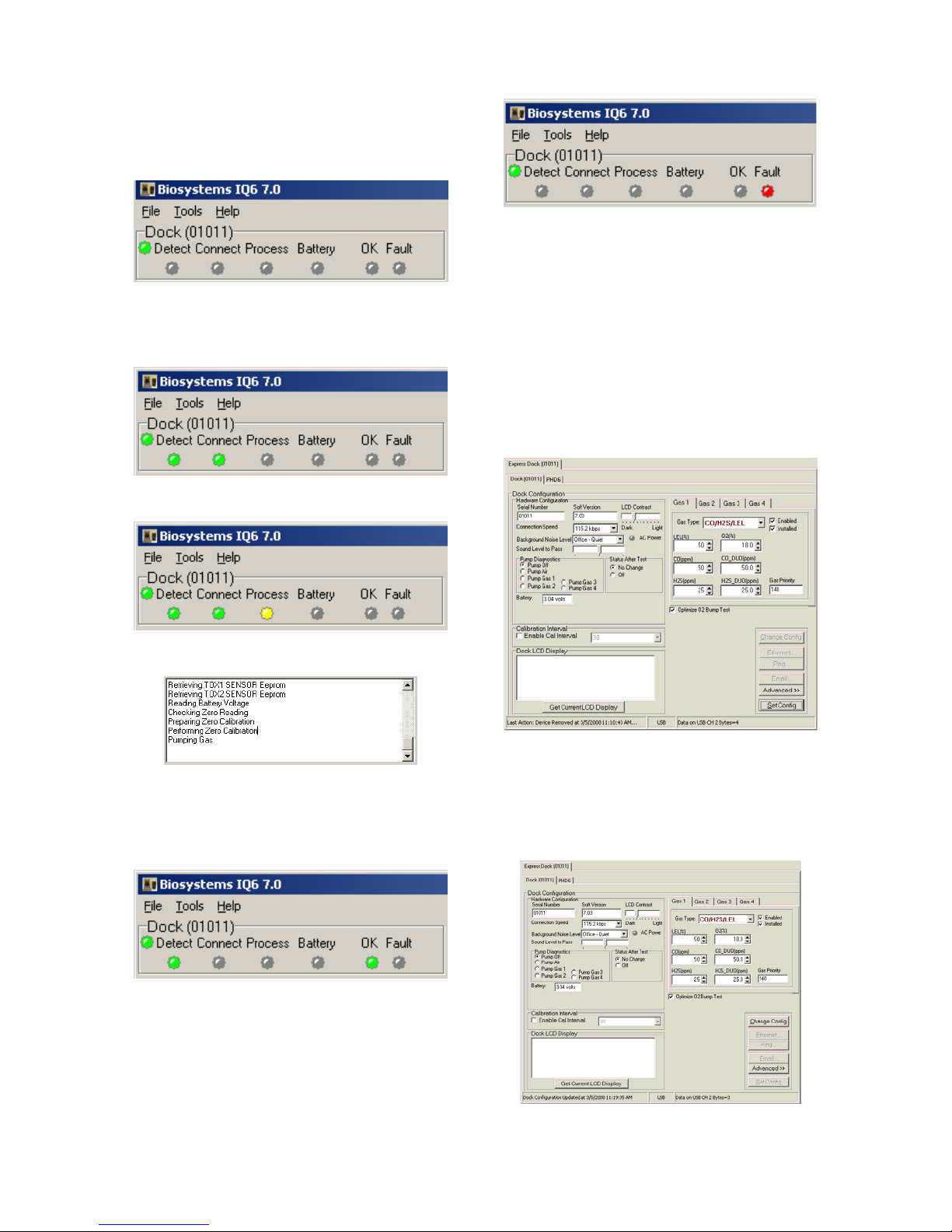
The current status of each dock is shown
in the left column. When there are no
detectors in the dock, each of the status
indicators will be shown in grey.
When a detector is placed in the dock,
the indicator will change to reflect the
new status. Status changes are also be
shown on the dock’s LCD.
During processing, the Processing
Indicator is shown in yellow.
The operations being performed on the
instrument are listed as they occur.
If the dock is able to successfully
complete the processing dictated by the
instrument’s template in the IQ Database
Manager Pro Program, OK will be shown
in green.
For more information regarding
template settings, see the IQ Database
Manager Pro Reference Manual.
If a fault is detected and the dock is
unable to complete the tests, the red fault
light will be shown on the screen. Details
of the fault will be listed in the input box
on the right side of the screen under the
instrument tab. See section 3.2.2 for
details on faults.
3.2 Dock Controls and Instrument
Status
The right side of the screen contains
individual controls for each IQ6 Dock.
Each dock has its own page, which can
be accessed by clicking on the
appropriate tab at the top of the page.
Within each dock’s page are two sub-
tabs. One contains specific information
on the dock itself. The other displays
information on the instrument that is
currently recognized in the dock.
Note: If the “Change Config” button
is enabled, press it before making any
changes to the settings.
3.2.1 Dock Configuration
Click on the Dock tab to access the dock
settings.
To change the configuration of the IQ6
Dock that is displayed, click on the
“Change Config” button at the lower right

13
of the screen. Once the dock
configuration is uploaded, the “Set
Config” button will be enabled. Once
changes are made, click on the “Set
Config” button to save the new settings.
Calibration
values shown in the Gas Values
columns must match those appearing
on the calibration gas cylinder(s) that
will be used to calibrate the detector.
Non-matching calibration gas and
calibration gas value settings will lead
to inaccurate and potentially
dangerous readings.
Hardware Configuration
The hardware configuration section
contains the serial number and software
version number of the dock at the upper
left corner.
This information may not be changed
with the software. Software updates will
cause the software version to change.
Connection Speed
The IrDA connection speed is given
below the serial number and software
version. The default connection speed is
38.4 kbps, although settings from 2400
bps to 115.2 kbps are available.
Sperian Instrumentation recommends
leaving the connection speed at the
default setting unless you are
experiencing frequent communication
problems in the form of a loss of
connection. If connection is frequently
lost, adjust the connection speed down
gradually until the problem is resolved.
Audible Alarm Sensitivity Controls
The audible alarm sensitivity controls
allow the user to customize the audible
alarm test criteria.
The Background Noise Level adjustment
offers four levels of background noise
levels. For the best results, select the
one that most closely approximates the
background noise level expected during
testing.
The Minimum Sound Level setting
determines the minimum amount of
sound required to pass the alarm test.
The higher the setting, the louder the
alarm will need to be to pass the test.
AC Power
The AC Power indicator is located
directly beneath the connection speed
setting. If the dock is being powered by
the USB cable, the AC Power will appear
grey. When the dock is being powered
by an AC power source, the AC Power
indicator will appear green.
or
Pump Diagnostics
Pump settings are controlled through the
Pump Control section on the Dock
Settings page.
Click “Pump Gas” along with the port
number to draw span calibration gas
through the right gas port at the back of
the dock.
Click “Pump Air” to draw the fresh air
sample through the Air input port.
The pump will run until “Pump Off” is
selected.
LCD Contrast Control
At the right side of the Dock
Configuration box is the LCD (Liquid
Crystal Display) Contrast Control.
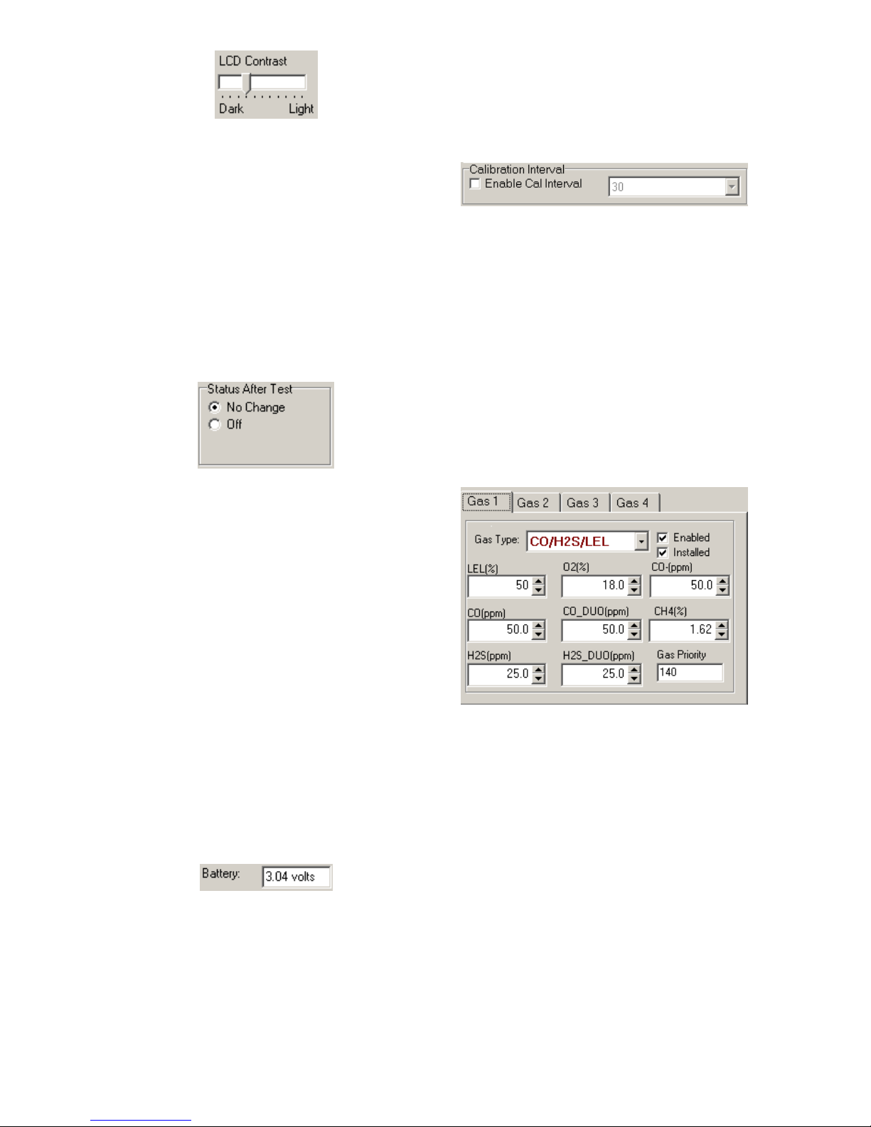
14
To darken or lighten the display on the
dock, move the slider as appropriate.
The dock will not show the new LCD
setting until the “Set Config” button is
pressed.
Status After Test
Once the IQ6 Dock finishes processing
an instrument, it can be programmed to
turn the instrument off, or to leave it in
the state that it was in (either on or off)
when it was placed in the dock. The
“Status After Test” control is located
beneath the LCD Contrast Control near
the center of the screen.
If “Status After Test” is set to Off, the
PHD6 will automatically be turned off by
the dock once the instrument has been
processed.
If “Status After Test” is set to “No
Change”, the instrument will return to the
state it was in when it was placed in the
dock.
In the case of rechargeable versions of
the PHD6 that will be charged in the IQ6
Dock after processing, Status After Test
must be set to “Off” to ensure that the
instrument will charge properly.
Battery
The battery level shown on the dock tab
is for the internal battery in the IQ6 Dock
. This battery serves to keep the real
time clock accurate while the dock is
unplugged and should not be a concern
to the user unless the battery level drops
below 2.50 Volts.
Calibration Interval
The Dock’s calibration interval settings
are controlled from the Dock Tab and are
located below the battery level and
above the LCD Display box. The dock’s
calibration interval is the maximum
number of days that the dock will allow to
pass between calibrations for any
instrument that is placed in the dock. If
an instrument is placed in the dock and
the interval has been exceeded, the dock
will automatically initiate a full span
calibration of the instrument regardless of
the results of the bump test or the
instrument’s own calibration status.
To use the setting, click on Enable Cal
Interval and set the interval to the
number of days between calibrations.
Note that this setting may cause the
instrument to undergo a full
calibration even when the instrument
itself is not due for calibration.
Gas Configuration
The calibration gas configuration for the
4 gas inlet ports on the back of the dock
is located on the right side of the window.
If the values are shown in red text, they
can be changed. If the values are shown
in black text and you wish to change
them, press “Change Config”.
Note: The gas values shown here are
the values that will be used in calibrating
PHD6 instruments that interface with the
dock regardless of the instrument’s own
built-in calibration gas settings.
To change the calibration gas value, first
select the Gas Port (Gas 1, Gas 2, Gas 3
or Gas 4). Then select the Gas Type
from the list.

15
Once the gas type is selected, use the
arrows to the right of the gas value input
box to increase or decrease the value.
If changes need to be made to the
settings for the other gas ports, click on
the Gas appropriate tab to access the
gas setting for Ports 2, 3 and 4 and
perform the same procedure.
Calibration
values shown in the Gas Port tabs
must match those appearing on the
calibration gas cylinder(s) that will be
used to calibrate the detector. Non-
matching calibration gas and
calibration gas value settings will lead
to inaccurate and potentially
dangerous readings.
Optimize O2 Bump Test
The IQ6 Dock is set to automatically
challenge oxygen sensors in the PHD6
with diminished levels of oxygen to verify
their response. For the oxygen sensor to
pass a bump test, calibration gas
containing less than 19.0% oxygen must
be connected to the dock and the
detector must detect the drop in oxygen
levels. If calibration gas with less than
19.0% oxygen is not detected, the PHD6
will automatically fail the oxygen bump
test.
The Optimize Bump Test option
controls how the oxygen test is
administered through the dock. The
“Optimize O2 Bump Test” option is
controlled by a checkbox that is located
below the Gas Configuration tabs on the
right side of the screen.
If “Optimize O2 Bump Test” is enabled
(checked), the IQ6 Express Dock will
automatically bump test the PHD6’s
oxygen sensor using the cylinder with the
lowest amount of oxygen available to the
IQ6 Dock.
If “Optimize O2 Bump Test” is disabled
(unchecked), the IQ6 Express Dock will
automatically bump test the PHD6’s
oxygen sensor using the cylinder with the
lowest amount of oxygen that is
necessary to process the other sensors
in the instrument.
Practical Example:
Two cylinders of gas are connected to
the IQ6 Express:
Cylinder 1 contains 50PPM CO, 25PPM
H2S, 50%LEL and 18.0% O2.
Cylinder 2 contains 10PPM SO2and
0.0% O2.
The PHD6 is a standard 4-gas model
with O2, LEL, CO and H2S sensors.
If “Optimize O2 Bump Test” is enabled,
the IQ6 Dock will bump test the O2
sensors using the Cylinder 2, which
contains 10PPM SO2 and 0.0% oxygen
– even though PHD6 isn’t equipped with
an SO2 sensor.
If “Optimize O2 Bump Test” is not
enabled, the IQ6 Dock will bump test the
O2sensors using the Cylinder 1 – which
contains all gases necessary to calibrate
this particular PHD6.
Saving new settings
When all necessary changes have been
made, press the “Set Configuration”
button to upload the new settings to the
dock.
The software will notify you once the
dock configuration has been updated.
Dock LCD Display
At the lower left corner of the Dock status
tab is Dock LCD Display window. This is
most often used when a dock is
controlled remotely via Ethernet where
the PC user is unable to physically see
the dock.

16
To view the dock’s Display, click on “Get
Current LCD Display”.
Ethernet Controls
For docks that are
connected by
Ethernet, there are
three additional
controls on the lower
right corner of the
display: Ethernet,
Ping and E-mail.
To view the Ethernet
settings, click on the
Ethernet button.
To test the dock connection, press the
Ping button. A status window will be
shown to indicate whether the ping was
successful or not.
The dock’s e-mail settings are controlled
through the Database Manager Pro
program, but can be viewed by clicking
on the e-mail button. The e-mail status,
IP Address of the dock, recipient e-mail
address and text of the e-mail message
are shown.
To test the e-mail ability of the dock,
press the Test E-mail button at the lower
left. An e-mail will be generated and sent
to the recipient e-mail address that is
listed.
Press OK to close the Email Setup
window.
3.2.2 PHD6 Tab
The PHD6 tab shows instrument
information for the detector that is
currently in the dock. The right side of
the tab is identical to the Dock Status tab
section discussed above. The blank
space at right is an output box that
shows detailed instrument information as
it is processed.
The output box is updated as the
instrument is detected, connected, and
processed. When faults occur, the
details of the fault will be shown and a
red fault light will be shown. Below, a
span calibration failure is the cause of
the fault.
If the datalogger has been downloaded,
the “View Session Data” control will
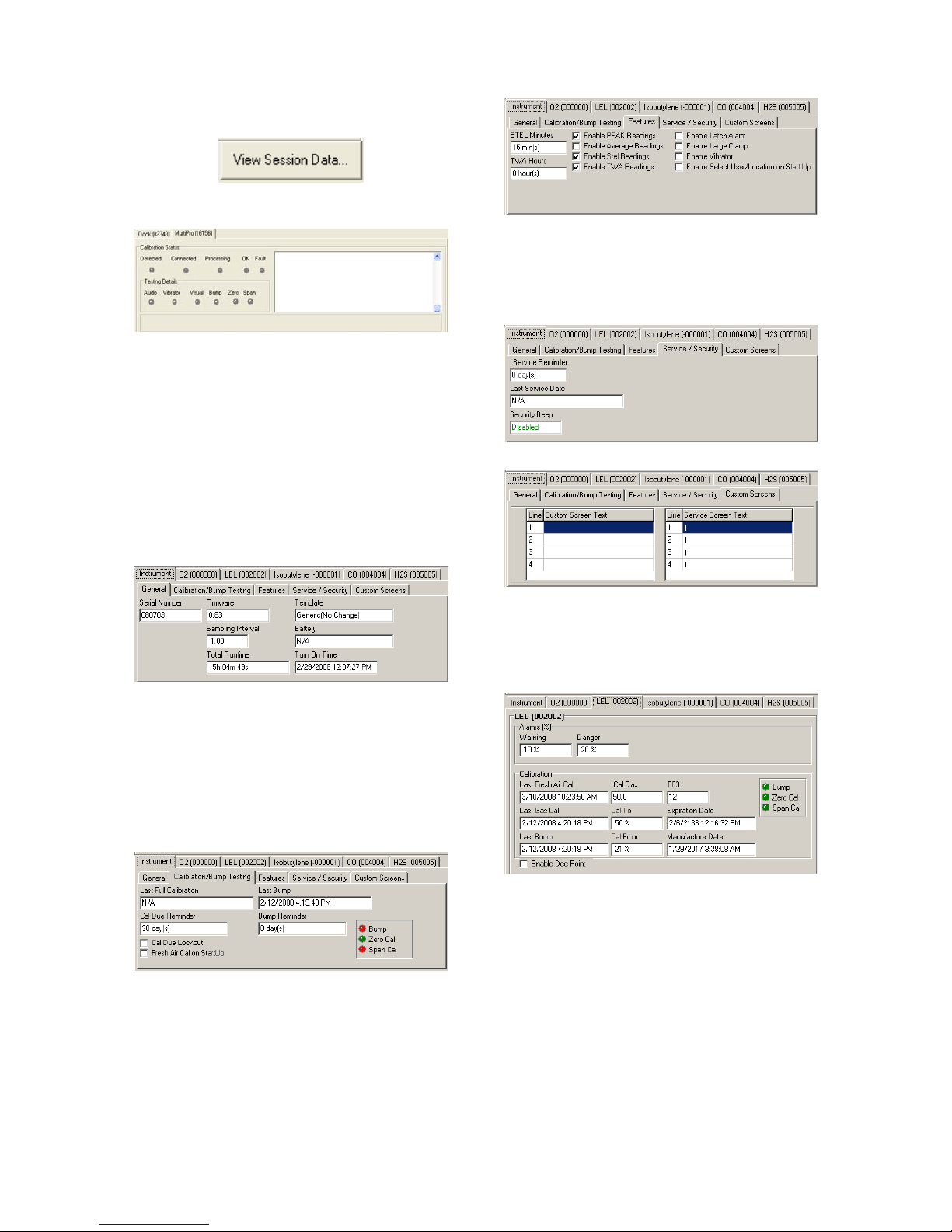
17
appear on the right. Click on “View
Session Data” to directly access session
information for the instrument using the
BioTrak Program.
If the dock is currently empty, none of the
status indicators will be lit.
3.2.2.1 Instrument Tab
The instrument tab contains 5 tab options
that control the configuration of the
PHD6.
General
The General Tab includes the instrument
serial number along with firmware, the
datalogger’s sampling interval, total
instrument runtime, the name of the
current IQ Template, battery level and
turn on time.
Calibration/Bump Testing
The Calibration/Bump Testing tab
contains the dates of the last calibration
and bump test, along with the Cal Due
and Bump Reminder settings. The Cal
Due Lockout option and Fresh Air Cal at
Startup options are check boxes at the
bottom of the window.
Features
The Features Tab includes the STEL and
TWA calculation controls. The Features
tab also includes the controls for
displaying Peak readings, average
readings, STEL readings and TWA
readings along with the Alarm Latch,
Large Clamp, Vibrating Alarm and the
requirement to select user and/or
location at startup.
Service/Security Tab
The Service/Security Tab includes the
Service Due Reminder setting along with
the Last Service Date and the Security
Beep setting.
Custom Screens
3.2.2.2 Sensors Tabs
Each sensor in the instrument has its
own tab that shows the alarm levels, and
most recent calibration data for the
sensor.
3.3 Advanced Settings / Passcode
The IQ6 Dock may be set to verify a
specific 4-digit passcode (PIN) in any
instrument that interfaces with the dock.
If the dock detects a PIN in the
instrument that matches its own PIN, it
will process the instrument. If the dock
fails to detect a PIN, or recognizes a non-
matching PIN, it will not process the
instrument.
To use the passcode feature a PIN must
be entered into the IQ6 Software and
then uploaded to every instrument that
will interface with the dock. Each dock
18
must then be programmed with the same
PIN and set to check for the code in the
instruments.
3. Select the dock that will be used to
write the PIN (Personal Identification
Number) to the instrument. Connect
the dock to the PC either by USB port
or by Ethernet port. If using an
Ethernet connection, the Ethernet
setting must be configured to “Live”.
If more than one dock will be used to
update the instruments, perform
steps 4-10 for each dock.
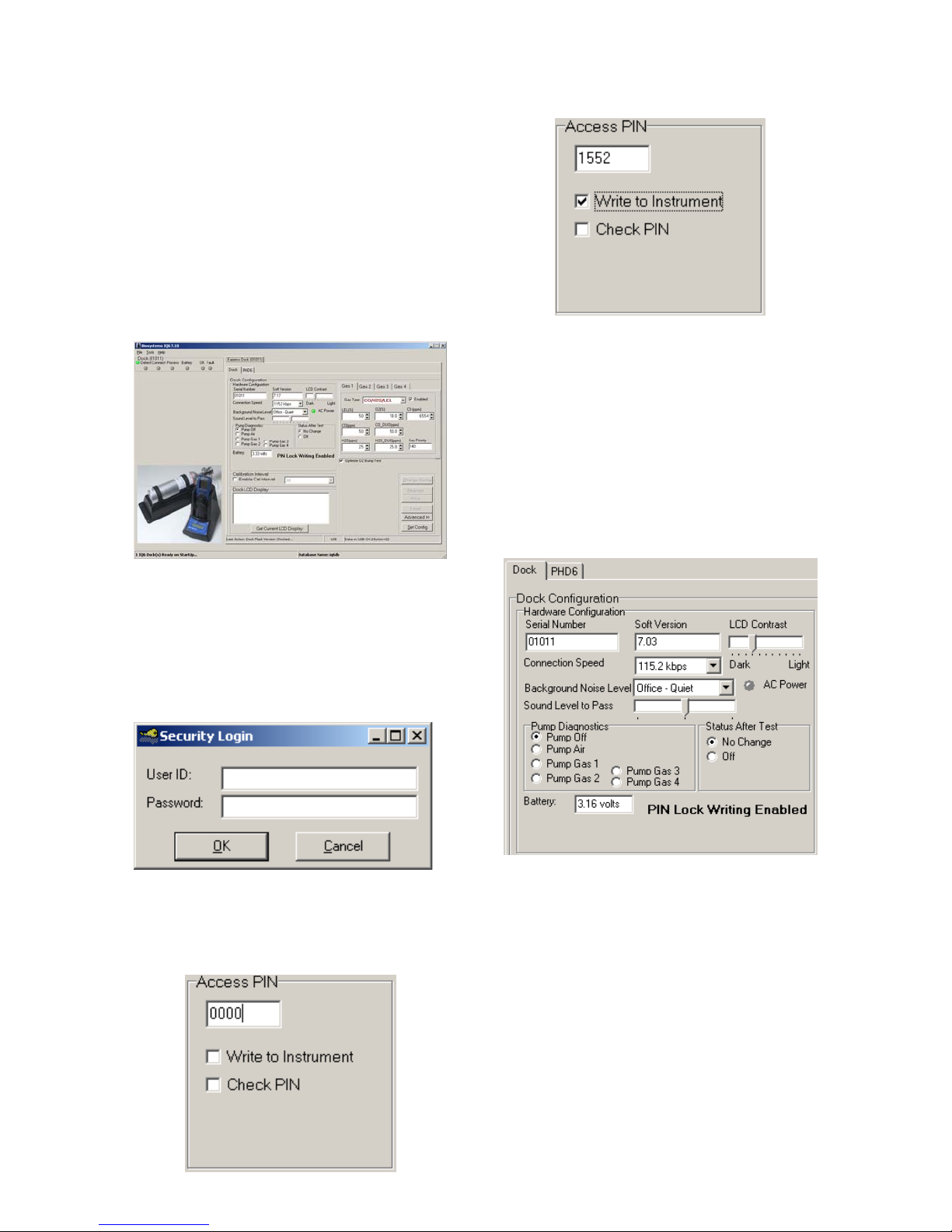
4. Open the IQ Express software.
5. Click “Advanced” in the row of
buttons on the lower right. The
software will automatically show the
Security Login screen and prompt
you for your user name and
password. If the “Advanced” button
is not shown, click on “Change
Config” first to access it.
6. Enter a valid User ID and Password.
The Access PIN settings will be
shown. The Access PIN at first
launch will be 0000, which should be
changed to something unique.
7. Enter a unique 4-digit PIN in the input
box under Access PIN and click on
“Write to Instrument”.
8. Click “Set Config” to tell the dock to
upload the PIN setting to the
instruments. The software will
automatically show the Security
Login screen a second time and
prompt you for your user name and
password. Once a valid User ID and
Password have been entered, “PIN
Lock Writing Enabled” will be shown
in the dock configuration window.
The dock is now ready to upload the
PIN to the instruments.
9. Place the instrument(s) that is/are to
be configured with the PIN in the
dock while PIN Lock Writing is
enabled.
10. Once the PIN has been uploaded to
all of the instruments, access the
dock’s advanced settings again and
click on “Check PIN”. Then click the
“Set Config” button.
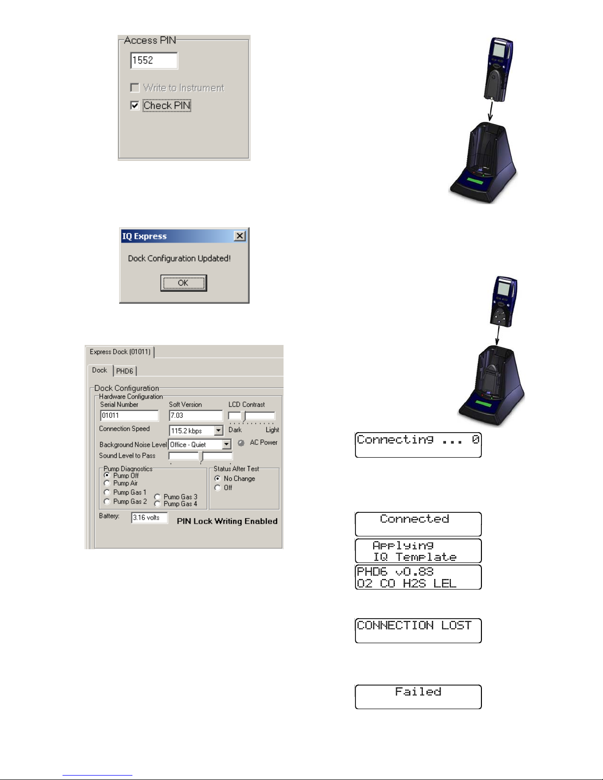
19
Enter your User ID and password again
when the Security Login window is
shown. A window will be shown to
indicate that the dock configuration has
been updated.
11. Click OK. “PIN Lock Enabled” will
then be shown in the PC software in
the dock configuration window.
The dock will now verify the PIN in any
instrument that interfaces with it.
12. For every other dock in the system,
access the dock’s advanced settings,
enter the PIN, click on “Check PIN”
and click the “Set Config” button.
With PIN lock enabled, only instruments
with a PIN matching the dock’s PIN will
be processed.
4. Dock Use
Once the IQ6 is connected to the gas
cylinder(s) and has been properly
configured, it is ready to accept the
PHD6 gas detector.
The PHD6 must be
turned on when it is
placed in the dock.
Note: If the PHD6 has
just been turned on,
wait at least three
minutes after the
conclusion of the
startup sequence to
allow the readings to
fully stabilize before
placing the instrument
in the dock.
Note: If a sensor has
just been replaced, it must be allowed
to stabilize before placing the
instrument in the dock. See the
sensor replacement section of the
PHD6 Reference Manual
for further information
on sensor stabilization.
If you plan to test the
instrument with the pump
attached, remove the
black spring clip from the
front of the dock prior to
inserting the PHD6 into
the dock.
Once the dock recognizes
the instrument, it will show
the following screens.
Once the connection is made, the IQ
Express will display “Connected”,
followed by the instrument type, software
version and recognized sensors.
If the connection is lost the following
screen will be shown:
If the instrument turns off prior to the
completion of the connection, Failed
will be shown:
Table of contents
Other GasTech Docking Station manuals


