GASTOP BR2 User manual

1
MONTAGE - BR2, GA2
MONTAGEDE
ENSEMBLE
FR
MONTAŻ
PL
MONTERING
SVMONTAGEEN
СБОРКА
RU
MONTAGGIO
IT
MONTAJE
ES

2
Complete documentation:
• GENERAL INFORMATION
• PEDESTRIAN TRAFFIC CONTROL
• DEVICE
• CONTROL MODULE
• MONTAGE
• MAINTENANCE AND SERVICE
• TECHNICAL DRAWINGS
EN
Documentation complète:
• INFORMATIONS GENERALES
• CONTRÔLE DE TRAFIC DE PASSAGERES
• DISPOSITIF
• MODULE DE CONTRÔLE
• ENSEMBLE
• MAINTENANCE ET ENTRETIEN
• DESSINS TECHNIQUES
FR
Komplette dokumentation:
• ALLGEMEINE INFORMATIONEN
• KONTROLLE DES PERSONENVERKERHS
• GERÄTE
• STEUERGERÄT
• MONTAGE
• WARTUNG UND INSTANDHALTUNG
• TECHNISCHE ZEICHNUNGEN
DE
Kompletna dokumentacja:
• INFORMACJE OGÓLNE
• KONTROLA RUCHU OSOBOWEGO
• URZĄDZENIE
• MODUŁ KONTROLNY
• MONTAŻ
• KONSERWACJA I UTRZYMANIE
• RYSUNKI TECHNICZNE
PL
Fullständig dokumentation:
• ALLMÄNT
• PASSAGEKONTROLL ALLMÄNNA REGLER
• ENHET
• STYRMODUL
• MONTERING
• UNDERHÅLL OCH SKÖTSEL
• TEKNISKA RITNINGAR
SV
Completa documentazione:
• INFORMAZIONI GENERALI
• CONTROLLO DELLA CIRCOLAZIONE DI PERSONE
• DISPOSITIVO
• MODULO DI COMANDO
• MONTAGGIO
• MANUTENZIONE E CONSERVAZIONE
• DISEGNI TECNICI
IT
Documentación completa:
• INFORMACIÓN GENERAL
• CONTROL DEL TRÁFICO PEATONAL
• DISPOSITIVO
• MÓDULO DE CONTROL
• MONTAJE
• MANTENIMIENTO Y SERVICIO
• DIBUJOS TÉCNICOS
ES
Полная документация:
• ОБЩИЕ СВЕДЕНИЯ
• КОНТРОЛЬ ДВИЖЕНИЯ ЛЮДЕЙ
• УСТРОЙСТВО
• УПРАВЛЯЮЩИЙ МОДУЛЬ
• СБОРКА
• УХОД И СОДЕРЖАНИЕ
• ТЕХНИЧЕСКИЕ ЧЕРТЕЖИ
RU

3
ENGLISH - DESCRIPTION OF DRAWINGS.........................................................12
DEUTSCH - BESCHREIBUNG DER ABBILDUNGEN......................................13
FRANÇAIS - DESCRIPTION DES DESSINS........................................................14
POLSKI - OPIS RYSUNKÓW......................................................................................15
SVENSKA - BESKRIVNING AV BILDERNA.........................................................16
ITALIANO - DESCRIZIONE DEI DISEGNI .............................................................17
ESPAÑOL - DESCRIPCIÓN DE LOS DIBUJOS..................................................18
РОССИЯ - ОПИСАНИЕ ЧЕРТЕЖЕЙ ...............................................19
EN
DE
FR
PL
SV
IT
ES
RU
4
A
1 2 3 5
4
13
12
11
10
9876
1
3A
2
3B
~50-100 KG
*BR2-T/T2/TM/F1/F2
GA2-T/TM *BR2-N2, GA2-N2
5
7B
4
6
7A
3C
5
*BR2-STI, BR2-STI2, GA2-STI
>30mm
ø50mm
*BR2-N2, GA2-N2
13mm
13mm
*BR2-T/T2/TM/F1/F2
GA2-T/TM

6
9B
9A
8B8C
7C8A
*BR2-STI, BR2-STI2, GA2-STI
*BR2-N2, GA2-N2 *BR2-STI, BR2-STI2, GA2-STI
*BR2-N2, GA2-N2
1,2m
1,2m
*BR2-T/T2/TM/F1/F2
GA2-T/TM
*BR2-T/T2/TM/F1/F2
GA2-T/TM
7
12
11
109C
14
13
*BR2-STI, BR2-STI2, GA2-STI
*BR2-TM, BR2-STI, BR2-STI2, GA2-TM, GA2-STI *BR2-F1, BR2-F2
1
2
90o
10cm

8
NC
NO
COM
NC
COM
NO
PIN DESCRIPTION ELECTRICAL INFO CONTROL SCHEME
1 LEFT DIRECTION - INPUT TTL Hi/Low
2 GND Imax = 1mA
3 RIGHT DIRECTION - INPUT TTL Hi/Low
4 GND Imax = 1mA
5 LEFT DIRECTION EN. - INPUT (LE) TTL Hi/Low
6 GND Imax = 1mA
7 RIGHT DIRECTION EN. - INPUT (RE) TTL Hi/Low
8 GND Imax = 1mA
9 FIRE EMERGENCY - INPUT (FE) TTL Hi/Low
10 GND Imax = 1mA
11 STOP EMERGENCY - INPUT (SE) TTL Hi/Low
12 GND Imax = 1mA
13 LEFT RETURN - OUTPUT NO Imax = 0,5A
14 LEFT RETURN - OUTPUT COM Imax = 0,5A
15 LEFT RETURN - OUTPUT NC Imax = 0,5A
16 RIGHT RETURN - OUTPUT NO Imax = 0,5A
17 RIGHT RETURN - OUTPUT COM Imax = 0,5A
18 RIGHT RETURN - OUTPUT NC Imax = 0,5A
INPUTSOUTPUTS
OUTER CONTROL SIGNALS
AND OUTER POWER SUPPLY
+5V
+5V
+5V
IP 65
24V AC
~
Tr
Pe
24 AC
IP 65 24 DC
AC/DC
Pe
N
C
Pe
N
C
230VAC
/110VAC
+
-
24V DC
Pe
230VAC
ALTERNATIVE POWER SUPPLY
2A
6A
9
1716
15
IN
C
C
AB
D
DEF
G
G
24V AC 50HZ
H
H
NO COM NC
INPUTS
OUTPUTS
GND
A-F
*BR2-TM, BR2-STI, BR2-STI2, GA2-TM, GA2-STI

10
2322
2120
1918
230/24V
AUTOMATIC
TEST TEST
MANUAL
1
2
90o

11
25
24

12
EN MONTAGE - BR2, GA2
ENGLISH - DESCRIPTION OF DRAWINGS
EN
Before installation, carefully read the full technical and operation documentation for the turnstile. This shortened installation manual is
strictly for the purpose of illustrating some of the important installation procedures.
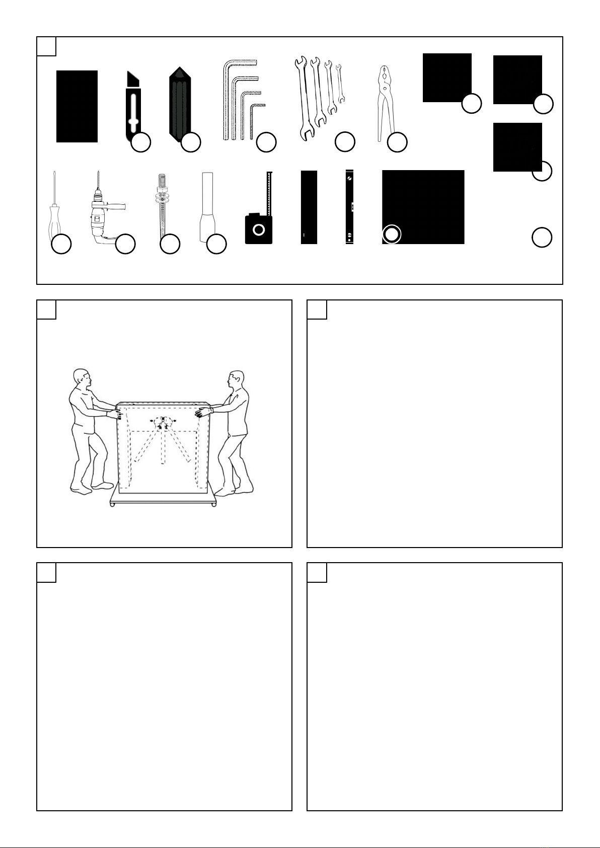
A. Tools and equipment needed for installation*:
1. Box cutter.
2. Marker for indicating hole positions on the oor.
3. Set of hex wrenches.
4. Set of open-ended wrenches.
5. Electrical wire crimping pliers.
6. Flat-blade screwdriver.
7. Drill with ø 12 mm drill bit.
8. Resin anchors (chemical).
9. Cable end sleeves.
10. Technical documentation.
11. Key/s for the lock/s on the unit cover.
12. Keys for blocking/unblocking the direction of trafc.
13. Transformer 230/24V.
*Tools and objects specied in points from 1 to 13 inclusive, are not a component part of the device set.
1. Transport of the unit from place to place must be carried out in accordance with healthe and other regulations.
2. Unpacking.
3. Removing the mounting holders.
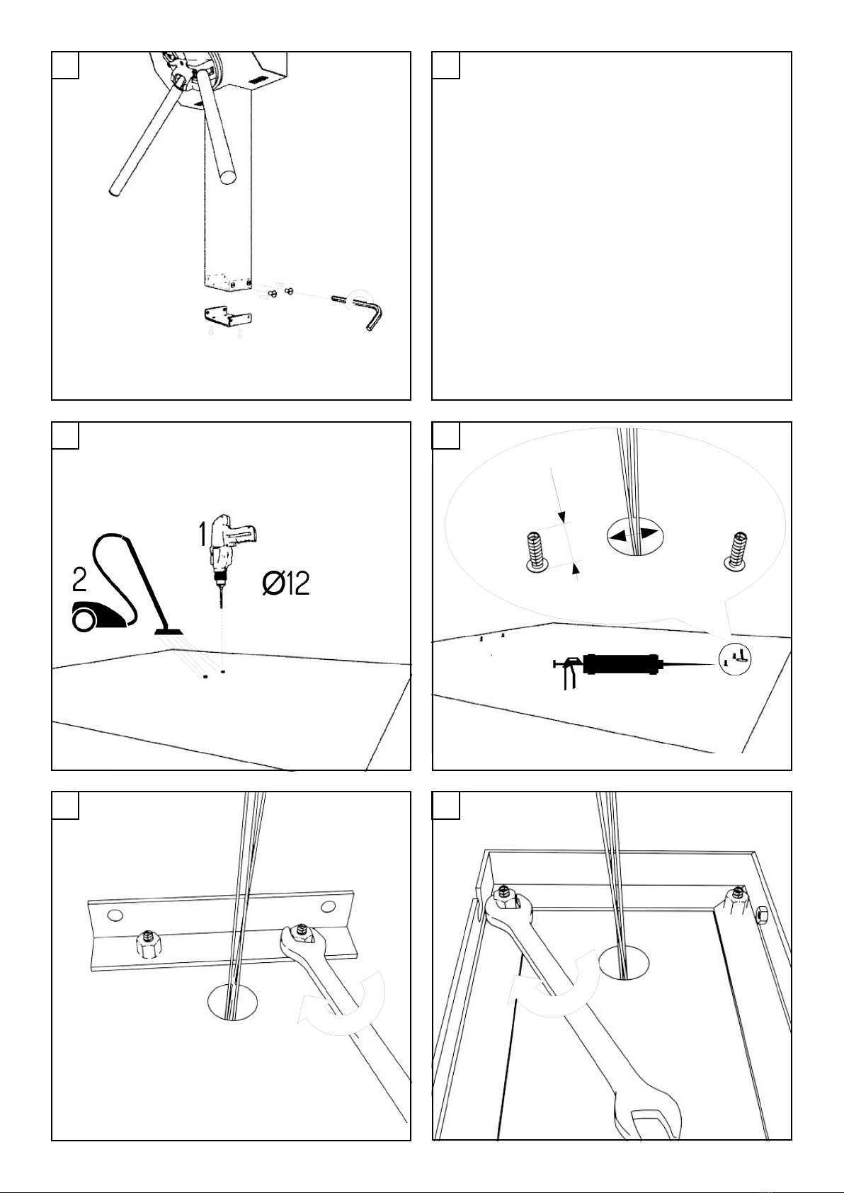
4. Marking the locations of holes to be drilled by using the mounting holder, and in accordance with the drawings in the technical and
operation documentation.
5. Drilling the ø12 mm holes to the depth recommended by the manufacturer of the resin anchors with a minimum depth of 100 mm.
6. The anchors should protrude at least 30 cm above the mounting surface. The recommended diameter of the hole for cable access
is 50 mm.
7. Placing the mounting holders on the anchors. After mounting spring washers, fasten the holders to the mounting surface with nuts.
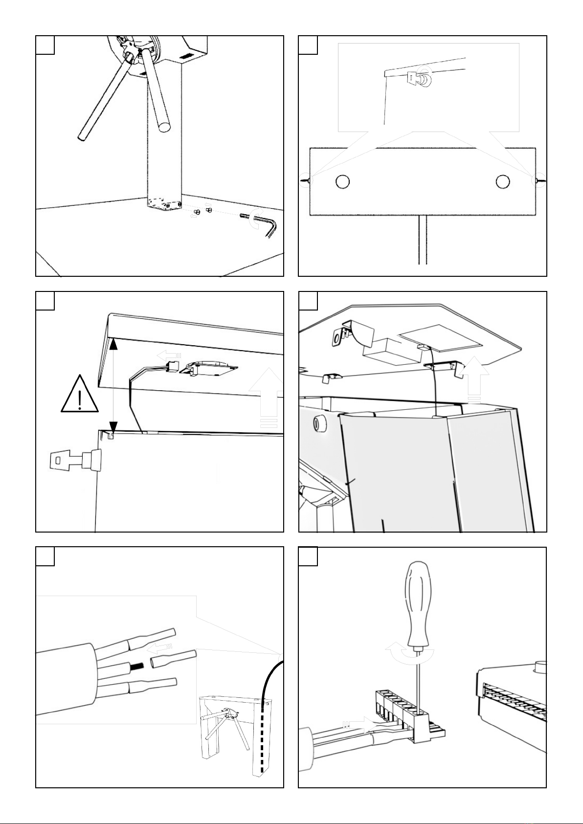
8. Mounting the unit on the mounting holders.
9. Mounting the unit on the mounting holders.
10. Unblocking the unit cover by turning the key/s in the lock/s.
11. Removing the unit cover (Note: in the case of units BR2-TM, BR2-STI, BR2-STI2, GA2-TM, GA2-STI the pictograms should be careful-
ly removed from the controller in order to avoid damaging the cables).
12. Removing the unit cover (Note: in the case of units BR2-F1, BR2-F2 the pictograms should be carefully removed from the controller
in order to avoid damaging the cables).
13. Crimping the cable end sleeve using the electrical wire crimpers.
14. Mounting the cable at the appropriate place in the terminal block.
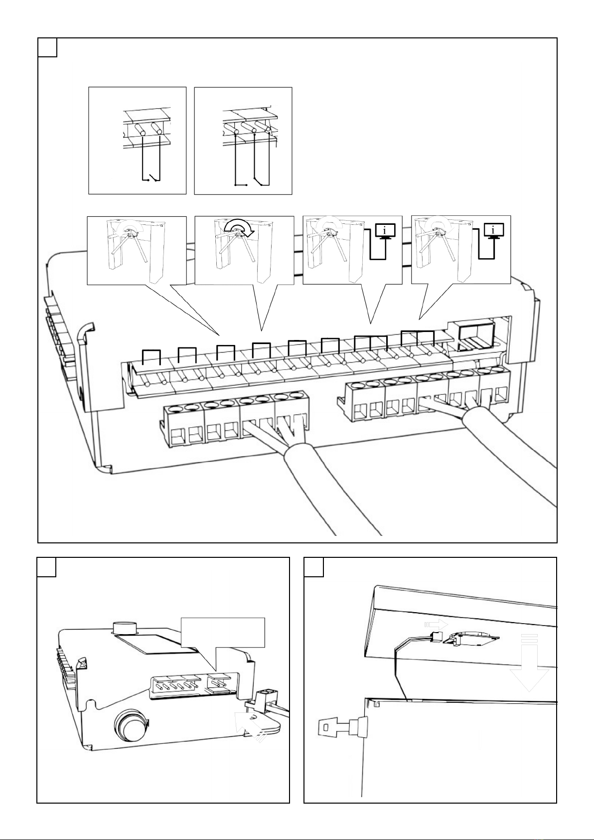
15. Connecting the basic signals to the controller. A detailed description can be found in the technical and operation documentation of
the unit.
16. Connecting the controller to the power supply.
17. Replacing the unit cover (in the case of units BR2-TM, BR2-STI, BR2-STI2, GA2-TM, GA2-STI rst attach the pictograms to the con-
troller).
18. Turning key/s in the lock/s to block the unit cover.
19. Connecting the unit to the 24V power supply.
20. Visual inspection of the diode pictograms.
21. Control test of the unit by introducing a signal from an external device (e.g. a control panel).
22. Handover of the technical and operation documentation to the owner/operator of the unit.
23. The operator supervising the unit reviews the technical and operation documentation.
24. The Rules and Information for Use are placed in a visible location, so that every user has access to them before using the unit.
25. Using the unit under the supervision of an operator.

13
DE MONTAGE - BR2, GA2
DEUTSCH - BESCHREIBUNG DER ABBILDUNGEN DE
Vor der Montage sollen Sie sich mit vollständigen technischen Inbetriebnahmeunterlagen vertraut machen. Dieser gekürzter Leitfaden
dient ausschließlich der Veranschaulichung einiger wichtiger Schritte bei der Montage des Gerätes.
A. Werkzeuge zum Anschneiden der Verpackung*
1. Ein Messer zum Anschneiden der Verpackung.
2. Ein Marker zur Kennzeichnung von Öffnungen am Boden.
3. Ein Set von Inbusschlüsseln.
4. Ein Set von Maulschlüsseln.
5. Eine Zange für Elektroinstallation.
6. Ein acher Schlitzschraubendreher.
7. Eine Bohrmaschine mit einem Bohrer Ř 12 mm.
8. Chemische Anker.
9. Buchsenenden für Leitungen.
10. Technische Dokumentation.
11. Ein Schlüssel/Schlüssel zum Deckelschloss.
12. Schlüssel zur Sperrung/Entsperrung von Bewegungsrichtungen.
13. Transformator 230/24V.
* Werkzeuge und Gegenstände von Ziff. 1 bis 9 sind keine Bestandteile des Sets.
1. Transport des Gerätes auf den Montageort nach den Arbeitssicherheitsvorschriften.
2. Auspacken.
3. Demontage des Griffes zur Gerätebefestigung.
4. Kennzeichnung der Stelle für Bohrung von Montageöffnungen mithilfe eines Befestigungsgriffes nach den Abbildungen der tech-
nischen Inbetriebnahmedokumentation.
5. Ausbohren von Öffnungen vom Durchmesser Ř 12 mm an den gekennzeichneten Stellen in der Tiefe, die vom Ankerhersteller
empfohlen wird, so dass die minimale Ankertiefe von 100 mm gewährleistet ist.
6. Die Anker haben mindestens 30 mm über dem Boden herauszuragen. Der empfohlene Öffnungsdurchmesser für die Verkabelung
beträgt 50 mm.
7. Legen des Befestigungsgriffes auf die Anker und nach Legen von Federunterlagen Zudrehen des Griffes an den Boden mit mit
Muttern.
8. Montage des Gerätes auf den Befestigungsgriffen.
9. Montage des Gerätes auf Befestigungsgriffen.
10. Entsperrung des Gerätedeckels nach dem Drehen des Schlüssels/der Schlüssel im Schloss/Schlössern.
11. Abnehmen des Gerätedeckels (Wichtig: Bei Geräten : BR2-TM, BR2-STI, BR2-STI2, GA2-TM, GA2-STI sind die Piktogramme vorsi-
chtig vom Steuergerät abzutrennen, ohne dass die Verkabelung zerrissen wird).
12. Abnehmen des Gerätedeckels (Wichtig: Bei Geräten : BR2-F1, BR2-F2 sind die Piktogramme vorsichtig vom Steuergerät abzutren-
nen, ohne dass die Verkabelung zerrissen wird).
13. Drücken des Buchsenendes in der Leitung mithilfe einer Zange für Elektroinstallationen.
14. Montage der Leitung an der entsprechenden Stelle der Klemmleiste.
15. Anschluss von Grundsignalen an das Steuergerät. Eine genaue Beschreibung von Anschlüssen bendet sich in der technischen
Inbetriebnahmedokumentation.
16. Anschluss des Steuergerätes an die Stromversorgung.
17. Legen des Deckels auf das Gerät (bei Geräten: BR2-TM, BR2-STI, BR2-STI2, GA2-TM, GA2-STI sind die Piktogramme an das Steuer-
gerät anzuschließen).
18. Drehen des Schlüssels/ der Schlüssel im Schloss/ Schlössern zur Deckelsperrung.
19. Anschluss des Gerätes an die Versorgungsquelle von Spannung 24V.
20. Sichtprüfung der Funktionsfähigkeit der Diodenpiktogramme.
21. Ein Test zur Prüfung der Funktionen des Gerätes z.B. durch Signalgabe aus dem Fremdgerät (z.B. einem Steuergerät).
22. Übergabe der betriebstechnischen Dokumentation dem Betreiber/Geräteinhaber.
23. Vertrautmachen mit der technischen Inbetriebnahmedokumentation durch den Gerätefunktionen beaufsichtigenden Mitarbeiter.
24. Anbringen der Betriebsanleitung des Gerätes an einer sichtbaren Stelle, so dass jeder Nutzer des Gerätes sich damit vor der
Nutzung des Gerätes vertraut machen kann.
25. Die Nutzung des Gerätes hat unter Aufsicht eines beaufsichtigenden Mitarbeiters/einer beaufsichtigenden Person zu erfolgen.

14
FR ENSEMBLE - BR2, GA2
FRANÇAIS - DESCRIPTION DES DESSINS
FR
Avant de procéder au montage veuillez prendre connaissance de la Documentation Technique d’Exploitation et de Maintenance du
dispositif. Cette notice abrégée ne sert qu’à illustrer quelques-unes des étapes importantes de l’installation du dispositif.
A. Outils et matériel nécessaires au montage du dispositif *:
1. Cutter pour couper l’emballage du dispositif.
2. Marquer pour marquage des points de perçage des trous de montage.
3. Jeu de clés Allen.
4. Jeu de clés plates.
5. Pince à sertir.
6. Tournevis plat.
7. Perceuse avec mèche Ř12 mm.
8. Ancrages chimiques.
9. Embouts de câble.
10. Documentation technique.
11. Clé(s) pour serrure(s) de capot.
12. Clés pour verrouiller et déverrouiller le sens de rotation.
13. Transformateur 230/24V.
* Les outils et matériel énumérés aux points de 1 à 9 ne sont pas fournis avec le dispositif.
1. Le transport des dispositifs vers le lieu de montage doit se faire conformément aux règles de sécurité et hygiène du travail.
2. Déballer le dispositif.
3. Démonter des pinces de serrage.
4. Marquer des points de perçage des trous de montage à l’aide des pinces de serrage et suivant les dessins gurant dans la Docu-
mentation Technique d’Exploitation et de Maintenance du dispositif.
5. Percer des trous les trous de 12 mm de diamètre aux points marqués selon la profondeur recommandée par le fabricant des bo-
ulons en sorte d’avoir la profondeur minimale d’ancrage égale à 100 mm.
6. Hauteur minimale du boulon mesurée depuis la surface du béton est de 30 mm. Le diamètre recommandé du conduit pour câbles
est de 50 mm.
7. Visser les pinces de serrage aux boulons et une fois les rondelles élastiques posées dessus, serrez les écrous de boulons.
8. Fixer le dispositif aux pinces de serrage.
9. Fixer le dispositif aux pinces de serrage.
10. Déverrouiller le capot du dispositif en tournant la (les) clé(s) dans la (les) serrure(s).
11. Enlever le capot du dispositif (Note: concerne les dispositifs BR2-TM, BR2-STI, BR2-STI2, GA2-TM, GA2-STI déconnecter soigneuse-
ment des pictogrammes du contrôleur pour ne pas briser le câblage).
12. Enlever le capot du dispositif (Note: concerne les dispositifs BR2-F1, BR2-F2 déconnecter soigneusement des pictogrammes du
contrôleur pour ne pas briser le câblage).
13. Serrer l’embout à l’aide d’une pince à sertir.
14. Raccorder le câble à la broche correspondante.
15. Raccorder de principaux signaux au contrôleur. La description détaillée des raccordements est présentée dans la Documentation
Technique d’Exploitation et de Maintenance.
16. Raccorder le contrôleur à l’alimentation.
17. Remettre le capot sur le dispositif (concerne les dispositifs BR2-TM, BR2-STI, BR2-STI2, GA2-TM, GA2-STI connecter d’abord des
pictogrammes au contrôleur).
18. Tourner la (les) clé(s) dans la (les) serrure(s) pour verrouiller le capot.
19. Connecter le dispositif à l’alimentation 24 V.
20. Effectuer le contrôle visuel de fonctionnement des pictogrammes à diodes.
21. Effectuer un test de fonctionnement du dispositif, p.ex. en envoyant un signal à partir d’un appareil externe (p.ex contrôleur).
22. Transmettre la Documentation Technique d’Exploitation et de Maintenance à l’opérateur / propriétaire du dispositif.
23. L’opérateur doit se familiariser avec la Documentation Technique d’Exploitation et de Maintenance.
24. Afcher le règlement/l’information relative à l’utilisation du diapositif dans un endroit visible pour que chaque utilisateur/opérateur
du dispositif puisse le lire avant d’utiliser le dispositif.
25. Utilisation du dispositif sous surveillance de l’opérateur/surveillant.

15
PL montaż - br2, GA2
POLSKI - OPIS RYSUNKÓW PL
Przed montażem należy zapoznać się z kompletną dokumentacją techniczno-ruchową urządzenia. Niniejszy skrócony podręcznik
instalacji służy wyłącznie w celu zobrazowania niektórych ważnych czynności procesu instalacji urządzenia.
A. Narzędzia i przedmioty potrzebne przy instalacji urządzenia*:
1. Nóż do nacięcia opakowania urządzenia.
2. Marker do oznaczenia otworów na podłożu.
3. Zestaw kluczy imbusowych.
4. Zestaw kluczy płaskich.
5. Szczypce do elektroinstalacji.
6. Śrubokręt płaski.
7. Wiertarka z wiertłem Ř12 mm.
8. Kotwy wklejane (chemiczne).
9. Końcówki tulejkowe do przewodów.
10. Dokumentacja techniczna.
11. Klucz/klucze do zamka/zamków pokrywy.
12. Klucze do blokowania i odblokowywania kierunków ruchu.
13. Transformator 230/24V.
*Narzędzia i przedmioty wymienione w punktach od 1 do 9 włącznie nie są częścią składową zestawu urządzenia.
1. Transport urządzenia na miejsce instalacji zgodnie z zasadami BHP.
2. Rozpakowanie.
3. Demontaż uchwytu mocującego urządzenia.
4. Oznaczenie miejsca wiercenia otworów montażowych z użyciem uchwytu mocującego oraz według rysunków dokumentacji tech-
niczno-ruchowej urządzenia.
5. Wywiercenie w wyznaczonych miejschach otworów o średnicy ø12 mm na głębokość zalecaną przez producenta kotew tak aby
zapewnić minimalną głębokość kotwienia równą 100 mm.
6. Kotwy powinny wystawać co najmniej 30 mm ponad powierzchnię podłoża. Zalecana średnica otworu na okablowanie wynosi 50
mm.
7. Nałożenie uchwytu mocującego urządzenia na kotwy i po nałożeniu podkładek sprężystych dokręcenie go nakrętkami do podłoża.
8. Zamontowanie urządzenia na uchwytach mocujących.
9. Zamontowanie urządzenia na uchwytach mocujących.
10. Odblokowanie pokrywy urządzenia po przekręceniu klucza/kluczy w zamku/zamkach.
11. Zdjęcie pokrywy urządzenia (Uwaga: w przypadku urządzeń BR2-TM, BR2-STI, BR2-STI2, GA2-TM, GA2-STI należy ostrożnie odłą-
czyć piktogramy od sterownika aby nie zerwać okablowania).
12. Zdjęcie pokrywy urządzenia (Uwaga: w przypadku urządzeń BR2-F1, BR2-F2 należy ostrożnie odłączyć piktogramy od sterownika
aby nie zerwać okablowania).
13. Zaciśnięcie końcówki tulejkowej na przewodzie przy użyciu szczypców do instalacji elektrycznych.
14. Zamontowanie przewodu w odpowiednim miejscu listwy zaciskowej.
15. Podłączenie podstawowych sygnałów do sterownika. Szczegółowy opis podłączeń znajduje się w dokumentacji techniczno-rucho-
wej urządzenia.
16. Podłączenie sterownika urządzenia do zasilania.
17. Założenie pokrywy na urządzenie (w przypadku urządzeń BR2-TM, BR2-STI, BR2-STI2, GA2-TM, GA2-STI najpierw podłącz pikto-
gramy do sterownika).
18. Przekręcenie klucza/kluczy w zamku/zamkach w celu zablokowania pokrywy.
19. Podłączenie urządzenia do źródła zasilania o napięciu 24V.
20. Kontrola wzrokowa działania piktogramów diodowych.
21. Test sprawdzający sprawność urządzenia np. przez podanie sygnału z urządzenia zewnętrznego (np. sterownika).
22. Przekazanie dokumentacji techniczno-ruchowej operatorowi/właścicielowi urządzenia.
23. Zapoznanie się z dokumentacją techniczno-ruchową przez nadzorującego pracę urządzenia operatora.
24. Umieszczenie regulaminu/informacji na temat użytkowania urządzenia w widocznym miejscu, aby każdy użytkownik/operator
urządzenia mógł się z nim zapoznać przed przystąpieniem do użytkowania urządzenia.
25. Użytkowanie urządzenia pod nadzorem operatora/osoby nadzorującej.

16
SV MONTERING - BR2, GA2
SVENSKA - BESKRIVNING AV BILDERNA
SV
Läs den kompletta drift- och underhållsmanualen innan monteringen påbörjas. Denna snabbinstallationsguide är endast avsedd att
illustrera vissa viktiga steg i installationsprocessen av utrustningen.
B. Verktyg och redskap som behövs vid installationen av utrustningen*:
1. Kniv för att skära upp förpackningen av utrustningen.
2. Penna för att markera hålen på underlaget.
3. Insexnyckelsats.
4. Skruvnyckelsats.
5. Elinstallationstång.
6. Skruvmejsel, platt.
7. Borrmaskin med borr Ř12 mm.
8. Injekteringsankare (kemiska).
9. Ändhylsor för kablar.
10. Teknisk dokumentation.
11. Nyckel/nycklar för låset/låsen i locket.
12. Nycklar för att låsa och låsa upp trakriktningar.
13. Transformator 230/24V.
*Verktyg och redskap som anges i punkterna 1 t.o.m. 9 medföljer ej.
1. Transport av utrustningen till installationsplatsen sker enligt säkerhetsföreskrifterna.
2. Packa upp.
3. Demontera fäste som håller utrustningen.
4. Markera borrställena för monteringshål med hjälp av en monteringskonsol och enligt ritningarna i drift- och underhållsmanualen.
5. Borra hål med diameter Ř12 mm på markerade platser till det borrdjup tillverkaren av ankare rekommenderar så att minsta föran-
kringsdjup är 100 mm.
6. Ankare bör sticka ut minst 30 mm ovanför underlagsytan. Rekommenderad håldiameter för kablar är 50 mm.
7. Placera monteringskonsolen på ankare, sätt fjäderbrickor och dra åt muttrar för att skruva fast konsolen ordentligt i underlaget.
8. Montera utrustningen på monteringskonsolerna.
9. Montera utrustningen på monteringskonsolerna.
10. Lås upp utrustningens lock genom att vrida nyckeln/nycklarna i låset/låsen.
11. Ta bort locket från utrustningen (Observera: var försiktig när du kopplar bort piktogram från styrenheten för grindarna BR2-TM,
BR2-STI, BR2-STI2, GA2-TM, GA2-STI så att du inte bryter upp kablarna).
12. Ta bort locket från utrustningen (Observera: var försiktig när du kopplar bort piktogram från styrenheten för grindarna BR2-F1,
BR2-F2 så att du inte bryter upp kablarna).
13. Pressa ändhylsan på trådarna med elinstallationstång.
14. Anslut kabeln till rätt plats i kopplingsplinten.
15. Anslut grundsignaler till styrenheten. En detaljerad beskrivning av anslutningen nns i drift- och underhållsmanualen.
16. Anslut styrenheten till strömuttaget.
17. Sätt locket på utrustningen (när det gäller grindarna BR2-TM, BR2-STI, BR2-STI2, GA2-TM, GA2-STI anslut först piktogram till
styrenheten).
18. Vrid nyckeln/nycklarna i låset/låsen för att låsa locket.
19. Anslut utrustningen till en 24V strömkälla.
20. Kontrollera visuellt att LED-piktogram fungerar som de ska.
21. Testa utrustningens funktion t.ex. genom att sända en signal från en extern enhet (t.ex. styrenhet).
22. Lämna drift- och underhållsmanualen till operatören/ägaren till utrustningen.
23. Den operatör som ska bevaka utrustningens funktion måste läsa drift- och underhållsmanualen.
24. Placera regler/information om användningen av utrustningen på en väl synlig plats så att alla användare/operatörer av utrustnin-
gen kan läsa den innan han eller hon använder utrustningen.
25. Användning av utrustningen under uppsikt av operatören/bevakaren.

17
IT MONTAGGIO - BR2, GA2
ITALIANO - DESCRIZIONE DEI DISEGNI IT
Prima del montaggio, leggere la completa documentazione tecnica dell’impianto. Il presente manuale abbreviato, serve soltanto per
illustrare alcuni attività importanti del processo di installazione.
A. Attrezzi e oggetti necessari durante l’installazione dell’impianto *:
1. Coltello per tagliare l’imballo dell’impianto.
2. Marker per contrassegnare i fori sul pavimento.
3. Kit chiavi a brugola.
4. Kit chiavi piatti.
5. Pinze per installazione elettrica.
6. Cacciavite a testa piatta.
7. Trapano con la punta Ř12 mm.
8. Ancoraggi chimici.
9. Estremità a boccola per i cavi.
10. Documentazione tecnica.
11. Chiave/chiavi per la serratura/serrature del coperchio.
12. Chiavi per bloccaggio e sbloccaggio Della direzione del movimento.
13. Trasformatore 230/24V.
*Attrezzi e oggetti elencati nei punti da 1 a 9 incluso, non fanno la parte dell’impianto.
1. Trasporto dell’impianto sul luogo di installazione, conforme con le norme di sicurezza e igiene do lavoro.
2. Disimballagio.
3. Smontaggio il manico di ssaggio dell’impianto.
4. Marcatura del posto di esecuzione dei fori di montaggio con utilizzo del manico di ssaggio e conformemente con i disegni della
documentazione tecnica dell’impianto.
5. Esecuzione dei fori del diametro di Ř12 mm nei posti indicati, alla profondità raccomandata dal produttore degli ancoraggi, per
garantire la minima profondità di ancoraggio, pari a 100 mm.
6. Ancoraggi devono uscire fuori almeno 30 mm sopra della supercie del pavimento diametro del foro, consigliato per i cavi e’ pari a
50 mm.
7. Inserimento del manico di ssaggio dell’impianto sugli ancoraggi e dopo applicazione delle rondelle elastiche ssaggio al pavimento
con i dadi.
8. Montaggio dell’impianto sulle staffe di ssaggio.
9. Montaggio dell’impianto sulle staffe di ssaggio.
10. Sbloccaggio del coperchio d’impianto dopo aver girato la chiave/ le chiavi nella serratura/ nelle serrature.
11. Asportazione del coperchio dall’impianto (Attenzione: Nel caso degli impianti BR2-TM, BR2-STI, BR2-STI2, GA2-TM, GA2-STI si deve
con la cautela scollegare i pittogrammi dal driver per non rompere il cablaggio).
12. Asportazione del coperchio dall’impianto (Attenzione: Nel caso degli impianti BR2-F1, BR2-F2 si deve con la cautela scollegare i
pittogrammi dal driver per non rompere il cablaggio).
13. Pressione della estremità a boccola sul cavo con utilizzo delle pinze per le installazioni elettriche.
14. Montaggio del cavo nell’apposito posto sulla morsettiera.
15. Montaggio del cavo nell’apposito posto sulla morsettiera.
16. Collegamento del driver all’impianto di alimentazione.
17. Inserimento del coperchio sull’impianto (nel caso degli impianti BR2-TM, BR2-STI, BR2-STI2, GA2-TM, GA2-STI prima collegare i
pittogrammi al driver).
18. Girare la chiave/le chiavi nella serratura/ nelle serrature per bloccare il coperchio.
19. Collegamento dell’impianto alla fonte di alimentazione di 24V.
20. Controllo Visual di funzionamento dei pittogrammi LED.
21. Test di controllo per vericare l’efcienza dell’impianto, per esempio dando il segnale dall’impianto esterno (prs. Driver).
22. Trasferimento della documentazione tecnica all’operatore/proprietario dell’impianto.
23. Operatore che supervisiona il lavoro dell’impianto, deve prendere in conoscenza la documentazione tecnica.
24. Posizionamento in un luogo ben visibile il regolamento/informazioni riguardanti il modo d’uso dell’impianto, per dare la possibilità
al utilizzatore/operatore dell’impianto di leggerla prima di iniziare l’uso dell’impianto.
25. Uso dell’impianto sotto la sorveglianza dell’operatore/persona sorvegliante.

18
ES MONTAJE - BR2, GA2
ESPAÑOL - DESCRIPCIÓN DE LOS DIBUJOS
ES
Antes del montaje se debe leer la documentación técnica completa del dispositivo. Este abreviado manual de la instalación pretende
mostrar los pasos más importantes del proceso de instalación.
A. Herramientas e ítems necesitados para la instalación del dispositivo*:
1. Cúter para abrir la caja del dispositivo.
2. Rotulador para marcar los agujeros en la base.
3. Kit de llaves allen.
4. Kit de llaves de dos bocas jas.
5. Pinzas para la electro instalación.
6. Destornillador plano.
7. Taladro de broca 12mm.
8. Anclajes químicos.
9. Terminales tipo ferrules aislados.
10. Documentación técnica.
11. Llave/llaves para cerradura/cerraduras de la cubierta.
12. Llaves para bloquear y desbloquear las direcciones de paso.
13. Transformador 230/24V.
*Herramientas e ítems mencionados en los puntos del 1 al 9 no forman parte del kit del dispositivo.
1. Transportar el dispositivo al lugar de instalación acorde con las reglas de seguridad y salud laboral.
2. Desempaquetar.
3. Desmontar el soporte de montaje.
4. Marcar los oricios para el montaje usando el soporte de montaje acorde con los dibujos incluidos en la documentación técnica del
dispositivo.
5. En los puntos marcados, perforar oricios de 12mm de diámetro hasta la profundidad recomendada por el fabricante de los anclajes
químicos para obtener una profundidad mínima de 100mm.
6. Los anclajes químicos tienen que estar al menos 30mm sobre la supercie. El diámetro recomendado para oricio del cableado es
de 50mm.
7. Colocar el soporte de montaje en los anclajes químicos y después de colocar las arandelas, atornillarlo con tuercas a la base.
8. Montar el dispositivo en el soporte de montaje.
9. Montar el dispositivo en el soporte de montaje.
10. Desbloquear la cubierta girando la llave/llaves dentro de la cerradura/cerraduras.
11. Retirar la cubierta del dispositivo (Atención: en el caso de dispositivos BR2-TM, BR2-STI, BR2-STI2, GA2-TM, GA2-STI desconectar
cuidadosamente los pictogramas del módulo de control para no romperlos).
12. Retirar la cubierta del dispositivo (Atención: en el caso de dispositivos BR2-F1, BR2-F2 desconectar cuidadosamente los pictogramas
del módulo de control para no romperlos).
13. Apretar el terminal tipo férrula asilado en el cable usando las pinzas para la electro instalación.
14. Montar el cable en el sitio apropiado en el terminal eléctrico.
15. Conectar las señales básicas al módulo de control. La descripción detallada de las conexiones puede ser encontrada en la docu-
mentación técnica del dispositivo.
16. Conectar el módulo de control a la fuente de energía eléctrica.
17. Colocar la cubierta en el dispositivo (En el caso de dispositivos BR2-TM, BR2-STI, BR2-STI2, GA2-TM, GA2-STI primero conectar los
pictogramas al módulo de control).
18. Girar la llave/llaves en la cerradura/cerraduras para bloquear la cubierta.
19. Conectar el dispositivo a la fuente de energía eléctrica con una tensión de 24V.
20. Revisar visualmente si los pictogramas funcionan.
21. Realizar una prueba para revisar el funcionamiento del dispositivo, por ejemplo enviando una señal desde un dispositivo externo
(por ejemplo módulo de control).
22. Entregar la documentación al operador/propietario del dispositivo.
23. Familiarización con la documentación técnica por parte del operador que supervisa la operación del dispositivo.
24. Ubicar las reglas/información acerca del uso del dispositivo en un sitio visible, de modo que cada usuario/operador pueda familiari-
zarse con ellas antes de usar el dispositivo.
25. Usar el dispositivo bajo vigilancia del operador/supervisor.

19
RU 22
RU
GA2-TM, GA2-STI
GA2-TM, GA2-STI

Other manuals for BR2
1
This manual suits for next models
1
Table of contents
Languages:
Other GASTOP Turnstile manuals


