GASTOP BR2 User manual
1
DEVICE - BR2, GA2, ZA2
GERÄTEDE
DISPOSITIFFR
URZĄDZENIEPL
DEVICEEN

2
Complete documentation:
• GENERAL INFORMATION
• PEDESTRIAN TRAFFIC CONTROL
• DEVICE
• CONTROL MODULE
• MONTAGE
• MAINTENANCE AND SERVICE
• TECHNICAL DRAWINGS
EN
Documentation complète:
• INFORMATIONS GENERALES
• CONTRÔLE DE TRAFIC DE PASSAGERES
• DISPOSITIF
• MODULE DE CONTRÔLE
• ENSEMBLE
• MAINTENANCE ET ENTRETIEN
• DESSINS TECHNIQUES
FR
Komplette dokumentation:
• ALLGEMEINE INFORMATIONEN
• KONTROLLE DES PERSONENVERKERHS
• GERÄTE
• STEUERGERÄT
• MONTAGE
• WARTUNG UND INSTANDHALTUNG
• TECHNISCHE ZEICHNUNGEN
DE
Kompletna dokumentacja:
• INFORMACJE OGÓLNE
• KONTROLA RUCHU OSOBOWEGO
• URZĄDZENIE
• MODUŁ KONTROLNY
• MONTAŻ
• KONSERWACJA I UTRZYMANIE
• RYSUNKI TECHNICZNE
PL

3
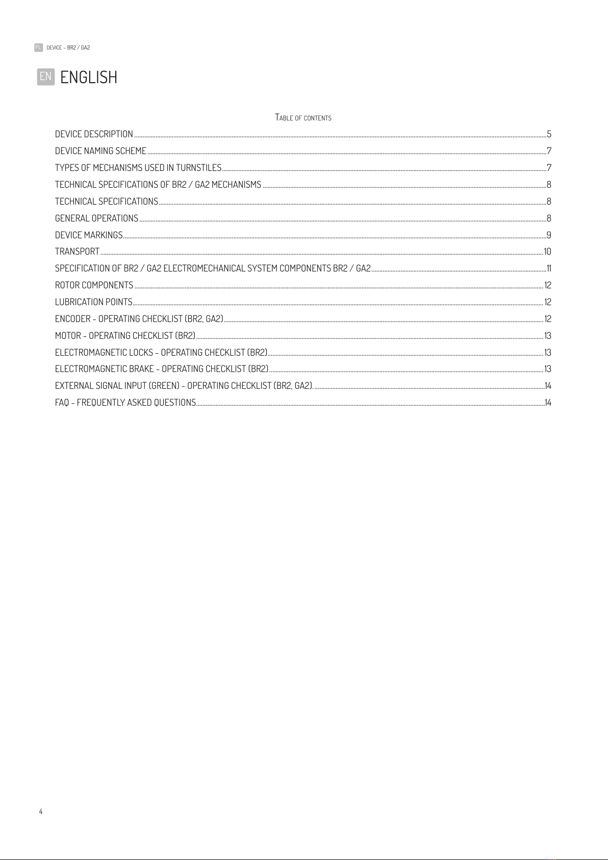
ENGLISH ...............................................................................................................................4
DEUTSCH ...........................................................................................................................18
FRANÇAIS ........................................................................................................................ 32
POLSKI ............................................................................................................................... 46
EN
DE
FR
PL
4
PL DEvICE - BR2 / GA2
TAbLE OF CONTENTS
DEVICE DESCRIPTION ��������������������������������������������������������������������������������������������������������������������������������������������������������������������������������������������������������������������������������������������������������������5
DEVICE NAMING SCHEME ������������������������������������������������������������������������������������������������������������������������������������������������������������������������������������������������������������������������������������������������������7
TYPES OF MECHANISMS USED IN TURNSTILES ��������������������������������������������������������������������������������������������������������������������������������������������������������������������������������������������������������7
TECHNICAL SPECIFICATIONS OF BR2 / GA2 MECHANISMS �������������������������������������������������������������������������������������������������������������������������������������������������������������������������������8
TECHNICAL SPECIFICATIONS �����������������������������������������������������������������������������������������������������������������������������������������������������������������������������������������������������������������������������������������������8
GENERAL OPERATIONS �����������������������������������������������������������������������������������������������������������������������������������������������������������������������������������������������������������������������������������������������������������8
DEVICE MARKINGS ���������������������������������������������������������������������������������������������������������������������������������������������������������������������������������������������������������������������������������������������������������������������9
TRANSPORT ���������������������������������������������������������������������������������������������������������������������������������������������������������������������������������������������������������������������������������������������������������������������������������10
SPECIFICATION OF BR2 / GA2 ELECTROMECHANICAL SYSTEM COMPONENTS BR2 / GA2 ������������������������������������������������������������������������������������������������������������11
ROTOR COMPONENTS ������������������������������������������������������������������������������������������������������������������������������������������������������������������������������������������������������������������������������������������������������������12
LUBRICATION POINTS �������������������������������������������������������������������������������������������������������������������������������������������������������������������������������������������������������������������������������������������������������������12
ENCODER - OPERATING CHECKLIST (BR2, GA2) ����������������������������������������������������������������������������������������������������������������������������������������������������������������������������������������������������� 12
MOTOR - OPERATING CHECKLIST (BR2) ����������������������������������������������������������������������������������������������������������������������������������������������������������������������������������������������������������������������13
ELECTROMAGNETIC LOCKS - OPERATING CHECKLIST (BR2) ��������������������������������������������������������������������������������������������������������������������������������������������������������������������������13
ELECTROMAGNETIC BRAKE - OPERATING CHECKLIST (BR2) ������������������������������������������������������������������������������������������������������������������������������������������������������������������������� 13
EXTERNAL SIGNAL INPUT (GREEN) - OPERATING CHECKLIST (BR2, GA2)� ����������������������������������������������������������������������������������������������������������������������������������������������14
FAQ - FREQUENTLY ASKED QUESTIONS �����������������������������������������������������������������������������������������������������������������������������������������������������������������������������������������������������������������������14
ENGLISH
EN
5
PL DEvICE - BR2 / GA2
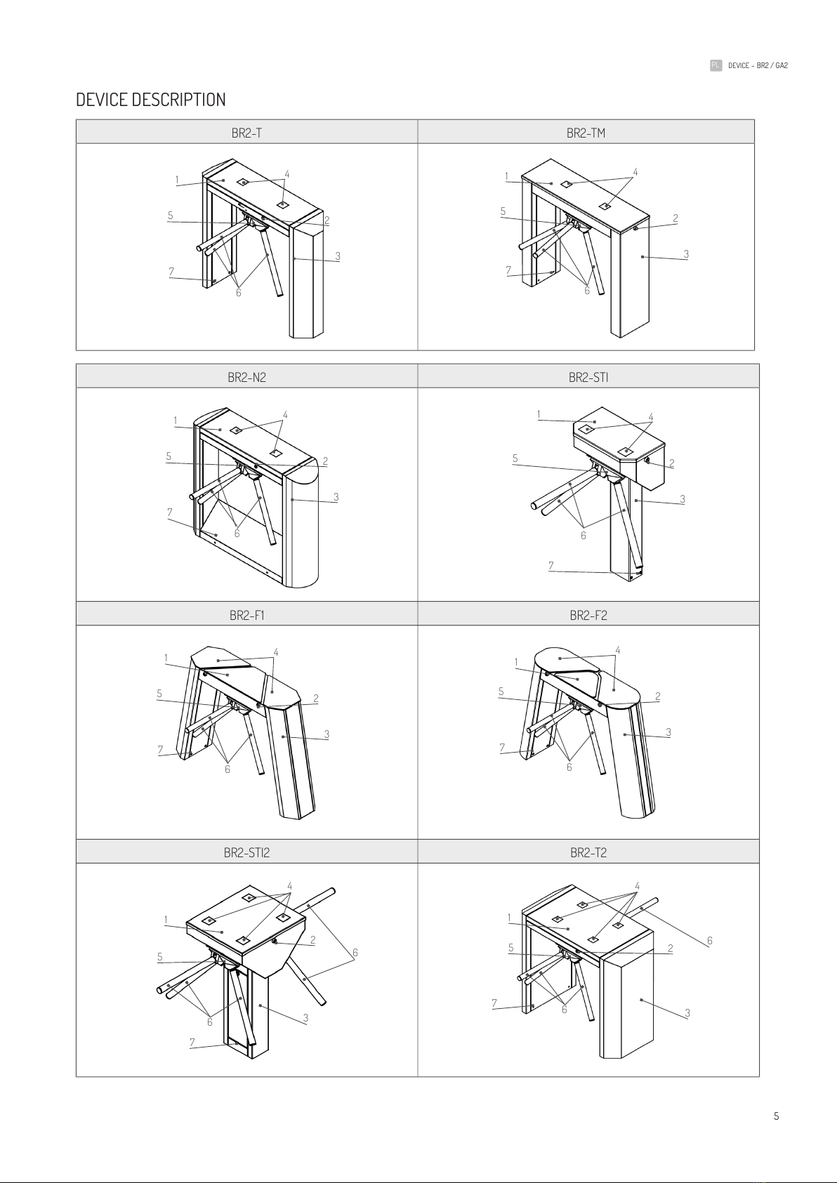
DEVICE DESCRIPTION
BR2-T BR2-TM
BR2-N2 BR2-STI
BR2-F1 BR2-F2
BR2-STI2 BR2-T2
1
7
5
6
4
3
2
1
7
5
6
4
3
2
1
7
5
6
4
3
2
1
7
5
6
4
3
2
1
7
5
6
4
3
2
6
1
7
5
6
4
3
26
1
7
5
6
4
3
2
1
7
5
6
4
3
2
6
PL DEvICE - BR2 / GA2
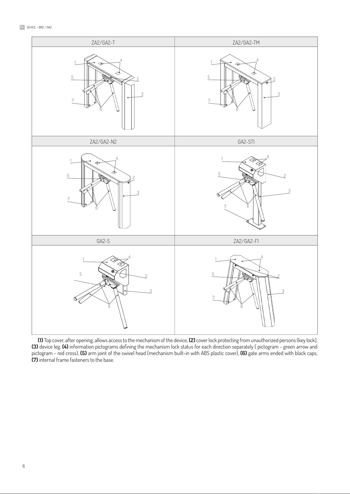
ZA2/GA2-T ZA2/GA2-TM
ZA2/GA2-N2 GA2-STI
GA2-S ZA2/GA2-F1
(1) Top cover, after opening, allows access to the mechanism of the device, (2) cover lock protecting from unauthorized persons (key lock),
(3) device leg, (4) information pictograms dening the mechanism lock status for each direction separately ( pictogram - green arrow and
pictogram - red cross), (5) arm joint of the swivel head (mechanism built-in with ABS plastic cover), (6) gate arms ended with black caps,
(7) internal frame fasteners to the base�
1
7
5
6
4
3
2
1
7
5
6
4
3
2
1
7
5
6
4
3
2
1
7
5
6
4
3
2
1
7
5
6
4
3
2
1
5
6
4
3
2
7
PL DEvICE - BR2 / GA2
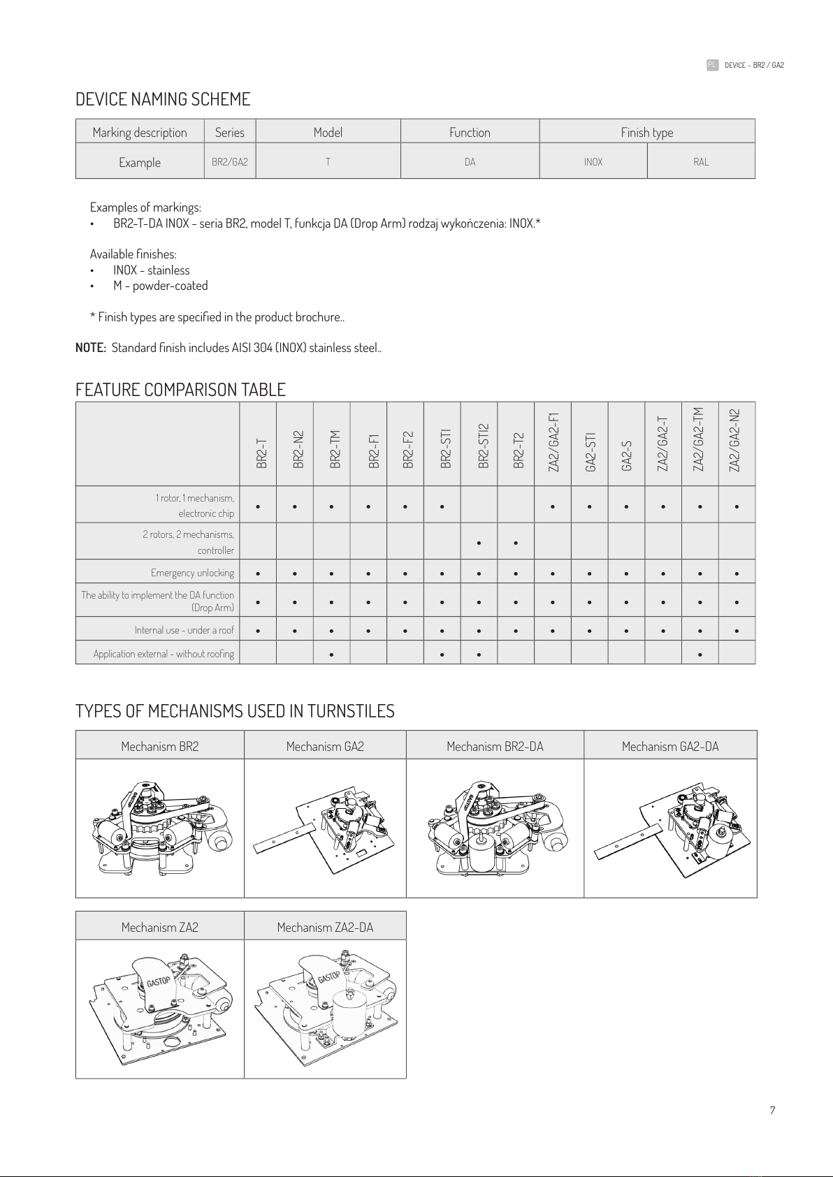
DEvICE NAMING SCHEME
Marking description Series Model Function Finish type
Example BR2/GA2 T DA INOX RAL
Examples of markings:
• BR2-T-DA INOX - seria BR2, model T, funkcja DA (Drop Arm) rodzaj wykończenia: INOX.*
Available nishes:
• INOX - stainless
• M - powder-coated
* Finish types are specied in the product brochure..
NOTE: Standard nish includes AISI 304 (INOX) stainless steel..
FEATURE COMPARISON TAbLE
1 rotor, 1 mechanism,
electronic chip • • • • • • • • • • • •
2 rotors, 2 mechanisms,
controller • •
Emergency unlocking ••••••••••••••
The ability to implement the DA function
(Drop Arm) ••••••••••••••
Internal use - under a roof ••••••••••••••
Application external - without roong • • • •
TYPES OF MECHANISMS USED IN TURNSTILES
Mechanism BR2 Mechanism GA2 Mechanism BR2-DA Mechanism GA2-DA
Mechanism ZA2 Mechanism ZA2-DA
BR2-T
BR2-N2
BR2-TM
BR2-F1
BR2-F2
BR2-STI
BR2-STI2
BR2-T2
ZA2/GA2-F1
GA2-STI
GA2-S
ZA2/GA2-T
ZA2/GA2-TM
ZA2/GA2-N2
8
PL DEvICE - BR2 / GA2
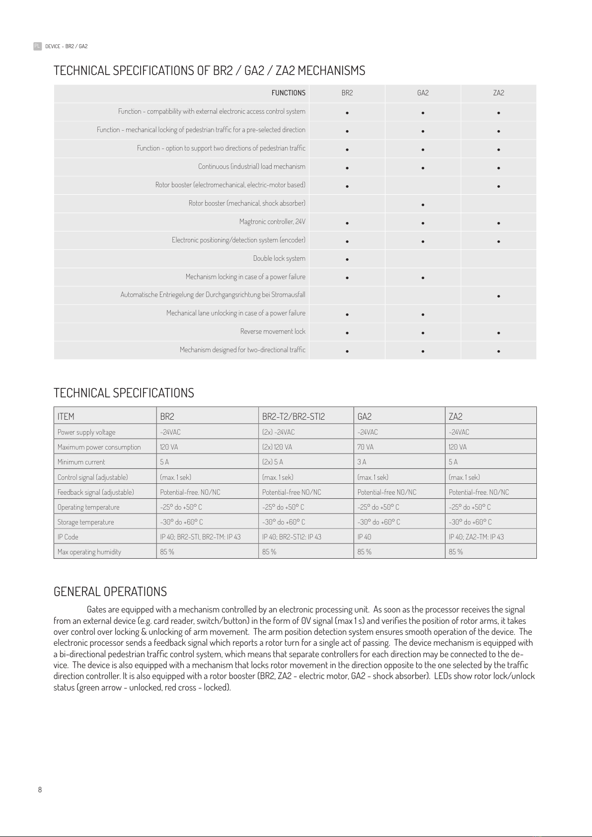
TECHNICAL SPECIFICATIONS OF bR2 / GA2 / ZA2 MECHANISMS
FUNCTIONS BR2 GA2 ZA2
Function - compatibility with external electronic access control system • • •
Function - mechanical locking of pedestrian trafc for a pre-selected direction • • •
Function - option to support two directions of pedestrian trafc • • •
Continuous (industrial) load mechanism • • •
Rotor booster (electromechanical, electric-motor based) • •
Rotor booster (mechanical, shock absorber) •
Magtronic controller, 24V • • •
Electronic positioning/detection system (encoder) • • •
Double lock system •
Mechanism locking in case of a power failure • •
Automatische Entriegelung der Durchgangsrichtung bei Stromausfall •
Mechanical lane unlocking in case of a power failure • •
Reverse movement lock • • •
Mechanism designed for two-directional trafc • • •
TECHNICAL SPECIFICATIONS
ITEM BR2 BR2-T2/BR2-STI2 GA2 ZA2
Power supply voltage ~24VAC (2x) ~24VAC ~24VAC ~24VAC
Maximum power consumption 120 VA (2x) 120 VA 70 VA 120 VA
Minimum current 5 A (2x) 5 A 3 A 5 A
Control signal (adjustable) (max. 1 sek) (max. 1 sek) (max. 1 sek) (max. 1 sek)
Feedback signal (adjustable) Potential-free. NO/NC Potential-free NO/NC Potential-free NO/NC Potential-free. NO/NC
Operating temperature -25° do +50° C -25° do +50° C -25° do +50° C -25° do +50° C
Storage temperature -30° do +60° C -30° do +60° C -30° do +60° C -30° do +60° C
IP Code IP 40; BR2-STI, BR2-TM: IP 43 IP 40; BR2-STI2: IP 43 IP 40 IP 40; ZA2-TM: IP 43
Max operating humidity 85 % 85 % 85 % 85 %
GENERAL OPERATIONS
Gates are equipped with a mechanism controlled by an electronic processing unit� As soon as the processor receives the signal
from an external device (e.g. card reader, switch/button) in the form of 0V signal (max 1 s) and veries the position of rotor arms, it takes
over control over locking & unlocking of arm movement� The arm position detection system ensures smooth operation of the device� The
electronic processor sends a feedback signal which reports a rotor turn for a single act of passing� The device mechanism is equipped with
a bi-directional pedestrian trafc control system, which means that separate controllers for each direction may be connected to the de-
vice. The device is also equipped with a mechanism that locks rotor movement in the direction opposite to the one selected by the trafc
direction controller� It is also equipped with a rotor booster (BR2, ZA2 - electric motor, GA2 - shock absorber)� LEDs show rotor lock/unlock
status (green arrow - unlocked, red cross - locked)�
9
PL DEvICE - BR2 / GA2
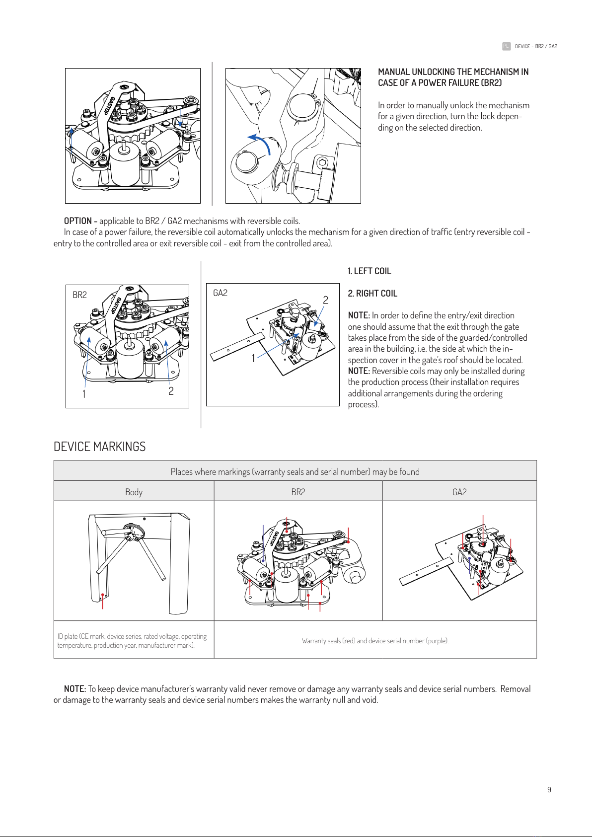
MANUAL UNLOCKING THE MECHANISM IN
CASE OF A POWER FAILURE (BR2)
In order to manually unlock the mechanism
for a given direction, turn the lock depen-
ding on the selected direction�
OPTION - applicable to BR2 / GA2 mechanisms with reversible coils�
In case of a power failure, the reversible coil automatically unlocks the mechanism for a given direction of trafc (entry reversible coil -
entry to the controlled area or exit reversible coil - exit from the controlled area)�
1. LEFT COIL
2. RIGHT COIL
NOTE: In order to dene the entry/exit direction
one should assume that the exit through the gate
takes place from the side of the guarded/controlled
area in the building, i�e� the side at which the in-
spection cover in the gate’s roof should be located�
NOTE: Reversible coils may only be installed during
the production process (their installation requires
additional arrangements during the ordering
process)�
DEvICE MARKINGS
Places where markings (warranty seals and serial number) may be found
Body BR2 GA2
ID plate (CE mark, device series, rated voltage, operating
temperature, production year, manufacturer mark). Warranty seals (red) and device serial number (purple).
NOTE: To keep device manufacturer’s warranty valid never remove or damage any warranty seals and device serial numbers� Removal
or damage to the warranty seals and device serial numbers makes the warranty null and void�
1
1
2
2
bR2 GA2

10
PL DEvICE - BR2 / GA2
TRANSPORT
MEANS OF TRANSPORT
Devices must be transported using covered means of transport� During the transport the devices must be secured against moving and
must be in a vertical position, unless otherwise specied by warning signs. Transport safeguards must be installed before transport.
SAFEGUARDS
By safeguards we mean fastening the load to a vehicle with straps/belts, ropes etc� Any device must be tied down to a truck on all sides�
Safe tiedown with ropes depends on the presence of adequate tiedown points in a means of transport� We recommend using high-
-strength textile ratchet straps with dedicated lifting hooks�
TRANSPORT RISKS
While using forklift trucks for transport pay special attention to maximum load and fork size� Use special equipment for any overhead
work� Never use any parts of the device for climbing�
PACKING & UNPACKING
For the sake of transport our devices are put in a protective plastic package� A single package contains a single unit�
The table below shows approximate weights of such packages, including the base and devices�
MODEL
WEIGHT ~ [kg/lbs] 75/165 60/132 75/165 70/154 70/154 58/127 75/165 75/165
MODEL
MOTOR VERSION
WEIGHT ~ [kg/lbs] 60/132 44/97 60/132 60/132 60/132 49/108 60/132 49/108 60/132 34/75
Packing procedures:
Device components must be packed in a vertical position only� Any points of contact with a forklift truck or other lifting machines must be
protected against damage� Check the package for completeness�
Unpacking procedures:
Make sure all transport safeguars have been removed� Check the device for any transport damage� Check the device for completeness�
In case of transport damage or lack of completeness inform the seller or shipping agent immediately� Use adequate tools to remove the
package (e�g� scissors or knives)� The package must be removed in accordance with environment protection regulations�
BR2-T
BR2-N2
BR2-TM
BR2-F1
BR2-F2
BR2-STI
BR2-STI2
BR2-T2
F1
GA2
ZA2
ZA2
ZA2
ZA2
GA2
GA2
GA2
GA2
GA2
T
TM
N2
STI
S
11
PL DEvICE - BR2 / GA2
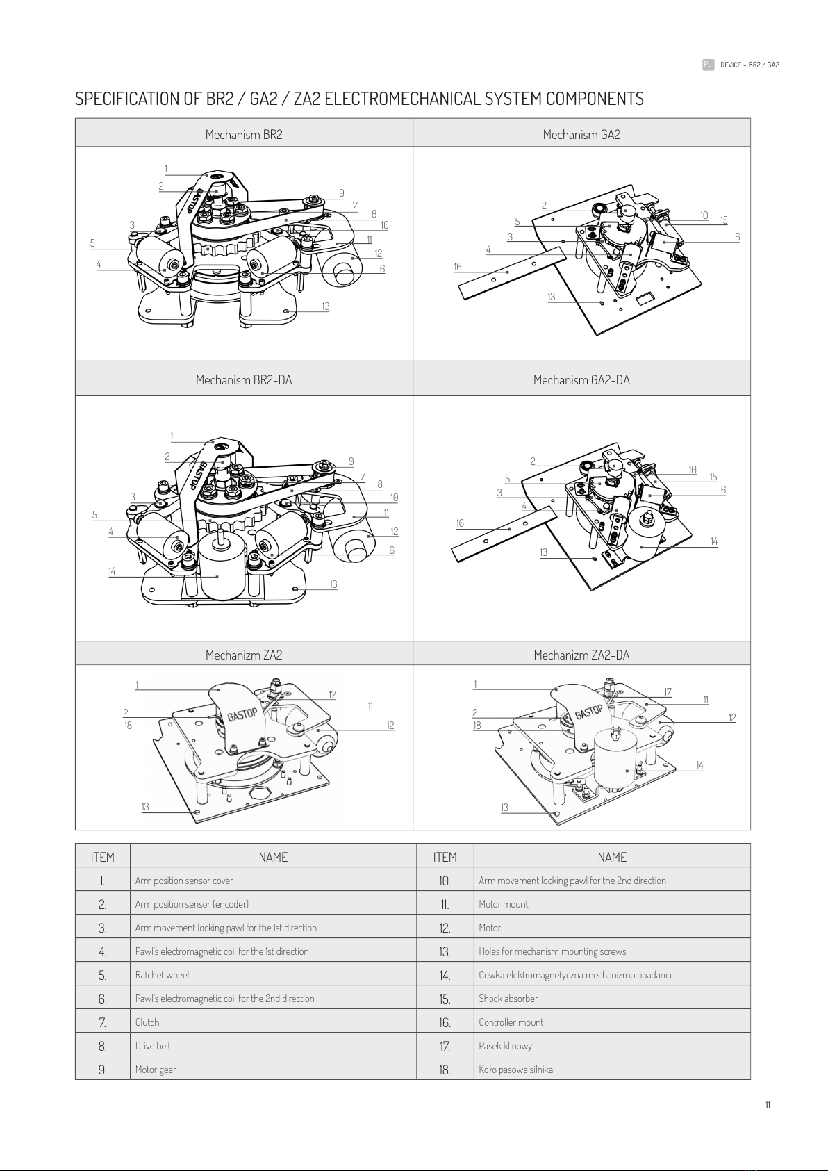
SPECIFICATION OF bR2 / GA2 / ZA2 ELECTROMECHANICAL SYSTEM COMPONENTS
Mechanism BR2 Mechanism GA2
Mechanism BR2-DA Mechanism GA2-DA
Mechanizm ZA2 Mechanizm ZA2-DA
ITEM NAME ITEM NAME
1. Arm position sensor cover 10. Arm movement locking pawl for the 2nd direction
2. Arm position sensor (encoder) 11. Motor mount
3. Arm movement locking pawl for the 1st direction 12. Motor
4. Pawl’s electromagnetic coil for the 1st direction 13. Holes for mechanism mounting screws
5. Ratchet wheel 14. Cewka elektromagnetyczna mechanizmu opadania
6. Pawl’s electromagnetic coil for the 2nd direction 15. Shock absorber
7. Clutch 16. Controller mount
8. Drive belt 17. Pasek klinowy
9. Motor gear 18. Koło pasowe silnika
1
2
3
4
5
3
5
4
14
13
13
16
8
10
10 15
11
12
6
6
9
7
2
14
1
2
3
4
5
3
5
4
13 13
16
8
10 10 15
11
12
6
6
9
7
2
1
1
2
2
13
13
17
17 11
11 12
12
14
18
18
12
PL DEvICE - BR2 / GA2
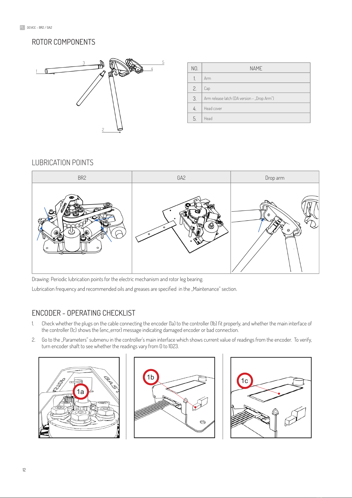
ROTOR COMPONENTS
NO. NAME
1. Arm
2. Cap
3. Arm release latch (DA version - „Drop Arm”)
4. Head cover
5. Head
LUBRICATION POINTS
BR2 GA2 Drop arm
Drawing: Periodic lubrication points for the electric mechanism and rotor leg bearing.
Lubrication frequency and recommended oils and greases are specied in the „Maintenance” section.
ENCODER - OPERATING CHECKLIST
1. Check whether the plugs on the cable connecting the encoder (1a) to the controller (1b) t properly, and whether the main interface of
the controller (1c) shows the (enc_error) message indicating damaged encoder or bad connection.
2. Go to the „Parameters” submenu in the controller’s main interface which shows current value of readings from the encoder. To verify,
turn encoder shaft to see whether the readings vary from 0 to 1023.
1a
1b 1c
1
2
3
4
5

13
PL DEvICE - BR2 / GA2
MOTOR - OPERATING CHECKLIST (BR2, ZA2)
1. Check whether the controller display shows a „motor error” message which may indicate bad connection between the controller and the
motor.
2. Check whether the motor, when turned, generates sounds indicating mechanical damage to the internal transmission which may have
resulted from excessive tension of the v-belt or over-tightening of the mounting bolts (2a) resulting in the clutch being inoperable.
3. Check motor cables. If motor cables are reversed, the motor may operate non-stop or turn in the opposite direction. Frequent changes
in motor direction may also occur.
ELECTROMAGNETIC LOCKS - OPERATING CHECKLIST (BR2)
1. Check whether electromagnetic locks (1a, 1b) are connected to proper output terminals of the controller (1c) (whether they are not reversed).
2. Manually check (when the device is disconnected from the power outlet) whether the coil’s core is free to move and the coil’s internal
spring automatically moves the core out of the coil.
ELECTROMAGNETIC BRAKE - OPERATING CHECKLIST (BR2, ZA2)
1. Check whether the brake is properly connected to the controller.
2. Use the ohmmeter to check the resistance of the electromagnetic brake which should be above 5 Ohm.
3. Check whether, when the device is disconnected from the power outlet, there is a gap between the upper and lower elements of the
brake (make sure the „free output” option is deactivated in the „SETTINGS” menu of the controller).
24V 0 V
1
3a 3b
2
1a
1b
1c
1
23
2a

14
PL DEvICE - BR2 / GA2
EXTERNAL SIGNAL INPUT (GREEN) - OPERATING CHECKLIST (BR2, GA2, ZA2)
1. Check whether connected external signal cables are not damaged and properly t the sockets (1a) and whether they are equipped with
anti-slippage terminals (1b).
2. Conduct a single authorization process by shorting 1 & 2 (2a) or 3 & 4 (2b) inputs of the controller (make sure the „free output” option is
deactivated in the „SETTINGS” menu of the controller).
FAQ - FREQUENTLY ASKED QUESTIONS
QUESTION 1 (BR2, ZA2): No response to external activation signals sent to external signal inputs – when activation signals
are sent to the device, it does not turn on the LEDs to indicate a passage option and/or the motor does not respond to the
rotor being pushed (no boost to rotor movement).
Check whether the 5A fuse has blown in the controller. If the fuse keeps blowing even when all the cables (save power)
are disconnected, the controller must be replaced (by authorized service personnel only).
Check whether the controller is connected to the power source (LEDs should be on, displaying various symbols).
Check whether external signal cables are properly connected to external signal (green) inputs and whether clamps t
sockets properly.
Verify motor to controller connection and operation.
Verify encoder to controller connection and operation.
Set the zero position and calibrate the device.
QUESTION 2a (BR2, ZA2): Arms move non-stop irrespective of activation signals. When connected to power, the
rotor turns steadily or changes the direction without any reasons.
Verify motor to controller connection and operation.
Verify encoder to controller connection and operation.
Motor-controlling transistor is damaged – if motor control cables are shorted, a transistor may be damaged. In such
a case the controller must be replaced.
QUESTION 2b (BR2, ZA2): When the device is fed with power, the rotor turns non-stop in one direction.
Verify encoder to controller connection and operation.
QUESTION 2c (BR2, ZA2): When the device is fed with power but without any open/unlock signal, the rotor turns non-
stop and LEDs are dimmed.
Likely cause - excessive voltage fed to the device. To diagnoze the cause, disconnect the LEDs. The device should
work properly when the LEDs have been disconnected. To eliminate the cause, adjust input voltage to the parameters
specied in the technical & operation manual.
2a 2b
1b
1a

15
PL DEvICE - BR2 / GA2
QUESTION 3 (BR2): Coil vibration or strange behavior – lock coils go up and down very quickly.
Verify coil type conguration in the controller menu. If reversible coils had been installed in the device, check whether
they have been set up properly in the controller menu.
Verify electromagnetic lock connection and operation.
Check whether the zero position has been set up properly – setting up the zero position incorrectly may result
in constant contact of the lock with the ratchet wheel and subsequent vibrations. Such a situation occurs mainly in
connections based on reversible coils.
QUESTION 4 (BR2): When an activation signal is sent from an external system (ARK connector - green plugs), the
activation signals allow more than one person to pass (i.e. allow more than one pass cycle based on one signal) or, for
instance, allow the rotor to move in the opposite direction.
Check the ARK connector (green plugs).
Check input signal conguration 1-4. If the problem occurs in 1-2 or 1-4 inputs, it may indicate that they have been
congured to function as lock or free passage. Instructions on how to modify input functions are specied in the
technical & operation manual.
Verify motor to controller connection and operation.
Verify encoder to controller connection and operation.
Manually check (when the device is disconnected from the power outlet) whether the coil’s core is free to move and the
coil’s internal spring automatically moves the core out of the coil.
QUESTION 5 (BR2, ZA2): Bad rotor operation, jerkiness, too fast, too slow, zero position skipping/missing.
Zero position has not been set. No calibration. When the controller has been reprogrammed or replaced, zero position
must be re-set and motor calibration carried out again. The process is specied in the controller section of the technical
& operation manual. After the calibration, the rotor speed may be adjusted in the controller menu.
QUESTION 6 (BR2, ZA2): No feedback signal is sent; it is too short or sent at a wrong time.
Check external signal connectors (green plugs).
Verify feedback signal conguration in the controller menu. The Magtronic controller allows setting the time when
the feedback signal is sent. It may indicate activation signal reception conrmation or rotor movement start or nish.
Feedback signal duration can also be congured. The settings for this function are specied in the controller section of
the technical & operation manual.
QUESTION 7 (BR2, ZA2): Electromagnetic brake vibrations. As soon as the electromagnetic brake is on, it generates
loud vibrations.
Electromagnetic brake disc has been installed incorrectly. Too large a gap between the disc and electromagnet
armature or improper (non-paralell) alignment of these elements may result in vibrations when the voltage is reduced.
Make sure the disc and electromagnet armature are aligned properly. This procedure may only be performed by
authorized service personnel.
QUESTION 8 (BR2, ZA2): No response to signals. When signals are sent, the passage stays closed (locked) and/or LEDs
do not show that passing is possible.
Check the ARK connector (green plugs).
Check the conguration in the controller menu. The gate’s inability to operate properly may result, for instance, from
setting it to operate in the “locked” mode in which the gate does not respond to any activation signals.
QUESTION 9 (BR2 , ZA2): When the external signal is sent, the gate gets unlocked in the proper direction, but when
a person has passed, the rotor/arm does not return to the zero position; it remains still and motor noise can be heard.
Check the tension of the cogged belt in the mechanism or adjust the clutch (the procedures may only be performed by

16
PL DEvICE - BR2 / GA2
authorized service personnel).
PYTANIE 10 (BR2, ZA2): The gate operates non-stop and regularly changes the direction.
Deactivate the “test mode” in the controller’s main menu.
QUESTION 11 (BR2, ZA2): Despite checking and a failure to identify any problems in the mechanism and controller, the
device still does not operate properly. For instance, it may sometimes start or stop on its own.
1. Check whether the device receives proper voltage.
2. Check whether the devices are not powered by the same source (phase) with high distortions (the same source
powers, for instance, three-phase devices, inverters, such as elevators, escalators, boom barriers).
3. Check whether any antennas/aerials which may emit EM elds are located near the device.
4. Check for any friction in the rotor rotational movement caused by, for instance, a failure to lubricate the bearings.
QUESTION 12 (BR2, ZA2): The fuse is blown as soon as the power is on.
When the power is off, disconnect any cables from the controller. Then restore the power to the controller and start
connecting cables one by one. A blown fuse indicates a bad component.
QUESTION 13 (BR2, ZA2): The gate stays locked when the card or chip is
brought near the access control sensor. The gate is connected to the access
control system.
To check gate operations, activate gate unlock by shorting controller’s
1-2 or 3-4 inputs. If the gate is unlocked properly, then the problem
lies outside the device.

17
PL DEvICE - BR2 / GA2

18
DE GERäT - BR2 / GA2
INHALTSvERZEICHNIS
BESCHREIBUNG DER GERÄTE �������������������������������������������������������������������������������������������������������������������������������������������������������������������������������������������������������������������������������������������19
GERÄTEBEZEICHNUNG ����������������������������������������������������������������������������������������������������������������������������������������������������������������������������������������������������������������������������������������������������������21
ARTEN DER MECHANISMEN �����������������������������������������������������������������������������������������������������������������������������������������������������������������������������������������������������������������������������������������������21
TECHNISCHE PARAMETER DER MECHANISMEN ����������������������������������������������������������������������������������������������������������������������������������������������������������������������������������������������������22
TECHNISCHE PARAMETER �������������������������������������������������������������������������������������������������������������������������������������������������������������������������������������������������������������������������������������������������22
ALLGEMEINES WIRKUNGSPRINZIP ��������������������������������������������������������������������������������������������������������������������������������������������������������������������������������������������������������������������������������22
BEZEICHNUNGEN AN GERATEN ��������������������������������������������������������������������������������������������������������������������������������������������������������������������������������������������������������������������������������������23
TRANSPORT ��������������������������������������������������������������������������������������������������������������������������������������������������������������������������������������������������������������������������������������������������������������������������������24
EINE DETAILLIERTE BESCHREIBUNG DER DETAILS DES ELEKTROMECHANIK BR2 / GA2 ������������������������������������������������������������������������������������������������������������25
BESCHREIBUNG DER ROTORELEMENTE BR2 / GA2 ��������������������������������������������������������������������������������������������������������������������������������������������������������������������������������������������26
PERIODISCHE SCHMIERSTELLEN �����������������������������������������������������������������������������������������������������������������������������������������������������������������������������������������������������������������������������������26
ENCODER - EIN VERFAHREN ZUR ÜBERPRÜFUNG DER KORREKTEN FUNKTION DES GERÄTES (BR2, GA2)����������������������������������������������������������������������26
MOTOR - PRÜFEN SIE DEN KORREKTEN BETRIEB (BR2) ����������������������������������������������������������������������������������������������������������������������������������������������������������������������������������27
MAGNETKUGELN - VERFAHREN ZUR ÜBERPRÜFUNG DER KORREKTEN FUNKTION (BR2) ����������������������������������������������������������������������������������������������������������27
ELEKTROMAGNETISCHE BREMSE - VERFAHREN ZUR FUNKTIONSPRÜFUNG (BR2) ������������������������������������������������������������������������������������������������������������������������27
ANSCHLUSS FÜR EXTERNE SIGNALE (BR2, GA2)� �������������������������������������������������������������������������������������������������������������������������������������������������������������������������������������������������28
FAQ - FRAGEN UND ANTWORTEN ����������������������������������������������������������������������������������������������������������������������������������������������������������������������������������������������������������������������������������28
DEUTSCH
DE

19
DE GERäT - BR2 / GA2
BESCHREIBUNG DER GERÄTE
BR2-T BR2-TM
BR2-N2 BR2-STI
BR2-F1 BR2-F2
BR2-STI2 BR2-T2
1
7
5
6
4
3
2
1
7
5
6
4
3
2
1
7
5
6
4
3
2
1
7
5
6
4
3
2
1
7
5
6
4
3
2
6
1
7
5
6
4
3
26
1
7
5
6
4
3
2
1
7
5
6
4
3
2

20
DE GERäT - BR2 / GA2
ZA2/GA2-T ZA2/GA2-TM
ZA2/GA2-N2 GA2-STI
GA2-S ZA2/GA2-F1
(1) Die obere Abdeckung ermöglicht nach dem Öffnen den Zugang zum Mechanismus des Geräts, (2) die Abdeckungssperre zum Schutz
vor nicht berechtigten Personen (Schlüsselschloss), (3) das Gerätebein, (4) Informationspiktogramme, die den Mechanismusverriegelun-
gsstatus für jede Richtung getrennt denieren ( Piktogramm - grüner Pfeil und Piktogramm - rotes Kreuz), (5) Armgelenk des Schwen-
kkopfes (Mechanismus eingebaut mit ABS-Kunststoffabdeckung), (6) Torarme mit schwarzen Kappen, (7) Befestigungselemente für den
Innenrahmen an Fußboden�
1
7
5
6
4
3
2
1
7
5
6
4
3
2
1
7
5
6
4
3
2
1
7
5
6
4
3
2
1
7
5
6
4
3
2
1
5
6
4
3
2
Other manuals for BR2
1
This manual suits for next models
2
Table of contents
Languages:
Other GASTOP Turnstile manuals

Popular Turnstile manuals by other brands


Alvarado
Alvarado MST Installation Instructions and Maintenance Guide

DSI
DSI DS400 Series Service & installation manual

Tansa
Tansa LTT 303 user manual

CAME
CAME SALOON Series installation manual

Rotech
Rotech TRISTAR J18 AT instructions

Controlled Access
Controlled Access HS400 Series Service & installation manual


