GASTRON GTC-200A User manual
Human Technology & Future
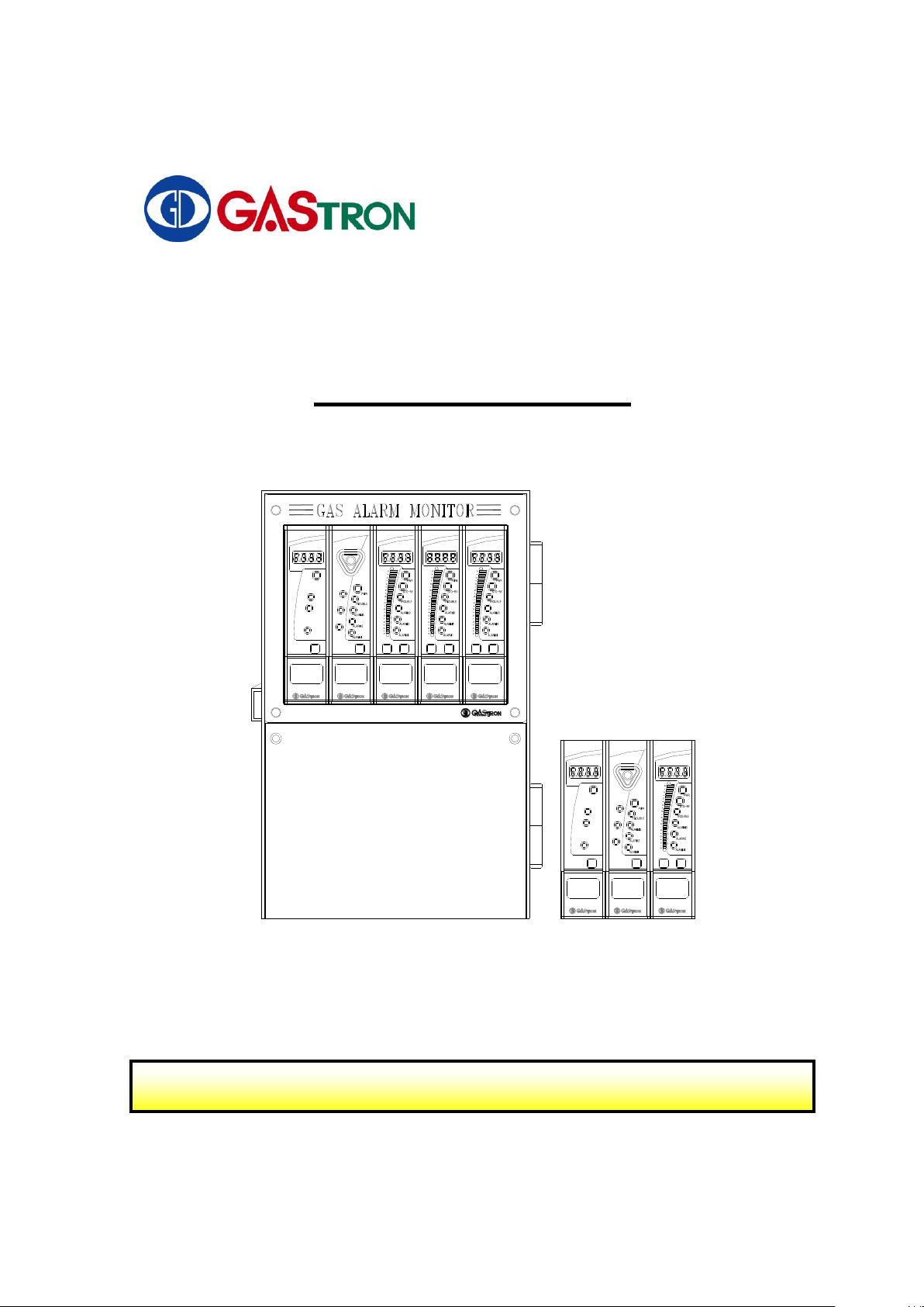
INSTRUCTION MANUAL
MODEL : GTC-200A
RESETTEST
0
10
20
30
40
50
60
70
80
90
100
GTC200A CHANNEL
%LEL
GTC200A
COM-PC
COM-CH
BZ. STOP
GTC200A COMMON
RESET
BZ. STOP
GTC200A
BATT TROUBLE
BATT GOOD
BATT POWER
MAIN POWER
BATT TEST
VOLT
GTC200A POWER
GTC200A
RESETTEST
0
10
20
30
40
50
60
70
80
90
100
GTC200A CHANNEL
%LEL
GTC200A
RESETTEST
0
10
20
30
40
50
60
70
80
90
100
GTC200A CHANNEL
%LEL
GTC200A
RESETTEST
0
10
20
30
40
50
60
70
80
90
100
GTC200A CHANNEL
%LEL
GTC200A
COM-PC
COM-CH
BZ. STOP
GTC200A COMMON
RESET
BZ. STOP
GTC200A
BATT TROUBLE
BATT GOOD
BATT POWER
MAIN POWER
BATT TEST
VOLT
GTC200A POWER
GTC200A
For proper use, please read this manual carefully!
GTC-200A
2
We much appreciate your wise purchase of GASTRON products
Gastron, a world-renowned company for manufacturing gas detectors and gas monitoring devices
exclusively, has enjoyed a great reputation from numerous consumers and customers in and out of
Korea for its superb quality and convenience in use. We, at Gastron, have always strived and will
further endeavor to let our consumers gain an easy access to our products at all times. Furthermore,
we are proud to let you know that Gastron has exerted ourselves to ceaselessly develop and
research for gas detectors catering to customers' satisfaction. Our customers are now invited to
solve all the problems and dissatisfaction related to gas detectors by using our Gastron products.
Our customers are warranted to receive contentment with our Gastron gas detectors at all times and
at any place.
The following operating manual serves to explain an installation method, an operating method, a
simple maintenance method and other useful guidelines regarding the toxic gas leakage detector
"GTC-200A" . We trust that this manual will be of good use whenever there are any questions or
inquiries during usage of the detector. You are encouraged to carefully read and make good use
of the operating manual by safekeeping and referring to the same at your every need.
As always, we once again appreciate your patronage of our products and should you have any
inconveniences or problems on our products, kindly contact us at the following address during
use to receive prompt attention and necessary measures.
Note
• You are kindly requested to get your gas detector inspected and calibrated at
least once within a three-month period using calibration gas according to the
type of gas in order to ensure an exact operation of the gas alarm, and to
receive a periodic inspection including one or more calibration inspections for
each six-month period under the provision of relevant Industrial Safety and
Sanitary Act promulgated by the Korea Labor Ministry.
• No periodic inspections and calibrations may be a cause of erroneous operation
of the gas detector due to aged sensor unit.
• The disintegration or disassembly of the gas detector needs a person who has a
technical expertise on the gas alarm.
• You are kindly invited to call our technical department or write to our e-mail
address or web site for inspection and calibration of gas detectors or alarms.

GTC-200A
3
C o n t e n t s
1. Introduction - - - - - - - - - - - - - - - - - - - - - - - - - - - - - - - 4
2. Features - - - - - - - - - - - - - - - - - - - - - - - - - - - - - - - - - 4
3. Specifications - - - - - - - - - - - - - - - - - - - - - - - - - - - - - - 5
4. Part’s name and major functions - - - - - - - - - - - - - - - - - 7
5. Terminal wiring diagram - - - - - - - - - - - - - - - - - - - - - - 14
6. How to use - - - - - - - - - - - - - - - - - - - - - - - - - - - - - - - - - 16
7. External Drawings and Dimensions - - - - - - - - - - - - - - - 26

GTC-200A
4
1. Introduction
GTC-200A Series has a high performance A/D converter and micro-processor so that it
has various functions built-in. GTC-200A Series is centralized, that is, composed of one
common alarm unit and several multi-channel control units. Each multi-channel control
unit is connected to its sensing part.
GTC-200A is encapsulated in DIN type case. There are two product types - Panel mount
type and Wall mount type.
GTC-200A has FND digital display (PV value) function and 3 colors LED bar graphic
display (PV & alarm set value) function, it also has three instant alarm (1st H/L, 2nd H/L,
and 3rd H/L) and trouble alarm.
2. Features
GTC-200A Series produces audible (buzzer) and visual (alarm LED and bar graphic LED
flashing) warnings in case of instant alarm and trouble alarm. If an alarm occurs, this
product can hold a Max. PV value holding.
GTC-200A series enables remote control for alarm cancellation. Our product can carry
out synchronous control functions because it has an output signal of the alarm (SPDT
contact).
GTC-200A series offers two outputs; Isolation type RS-485 signal (Option) is provided
for a monitoring system from common unit, the other is a measurement output (4-20mA,
DC) from channel control unit.
Since GTC-200A series is composed of the state of art parts, it has stability and
credibility. It can be expanded as large as its maximum (up to 64 channels)

GTC-200A
5
3. Specifications
3-1. Power Unit (Option)
Power Unit
1
Input power
DC. 24V
2
Output power
DC. 24V (Aux. power : DC. 27V / 300mA)
3
Output power display
FND Digital Display
4
Main power display
Green LED
5
Aux. power display
Green LED
6
Aux. power monitoring
Red LED
7
Aux. power test
Aux. power test S/W
8
Aux. power
Ni-Cd Battery 24V / 600mA(under 6 channels)
3-2. Common Unit
Common Alarm Unit
1
Input type
RS-485
2
Input check interval
100ms
3
Alarm type
Audible(Buzzer) & Visible (LED)
4
Alarm reset
Manual (Reset Switch)
5
Control input
Remote Reset–Buzzer stop/reset
6
Measuring output
Isolation RS-485 (Option)
7
Alarm output
Buzzer - STDT Relay Dry contact Signal Output
Fault Alarm- STDT Relay Dry contact Signal Output
1st Alarm - STDT Relay Dry contact Signal Output
2nd Alarm - STDT Relay Dry contact Signal Output
3rd Alarm - STDT Relay Dry contact Signal Output
* Relay Dry contact capacity : AC125V 10A
8
Operating Power
DC 24V
GTC-200A
6
3-3. Channel Unit
Channel Control Unit
1
Input type
4-20mA.DC / Full Scale
2
Measurement display
0.000 to 9999 Digital (settable by user)
3
Measurement
Accuracy
FND Digital –bigger one between ±1% Full Scale or 1 Digit
LED Bar --- bigger one between ±1% Full Scale or 1 Digit
4
Input check interval
100 ms
5
Alarm setting
3 stage Alarm (settable by user)
6
Alarm setting display
3 Color Bar Graphic (Green/Red/Yellow LED)
7
Alarm display
LED Bar Graphic
8
Alarm reset
Manual (Common Unit)
9
Self diagnosis
Test Switch & Reset Switch
10
Control In/out
RS-485
11
Measurement Output
4-20mA.DC / Full Scale
12
Alarm Output
Fault Alarm - STDT Relay Dry contact Signal Output
Alarm 1 STDT Relay Dry contact Signal Output
Alarm 2 STDT Relay Dry contact Signal Output
Alarm 3 STDT Relay Dry contact Signal Output
* Relay Dry contact capacity : AC125V 10A
13
Operating Power
DC 24V
3-4. Wall Mount Type
Wall Mount Type
1
Input Power
AC 110V/220V 50/60Hz (default: AC220V 50/60Hz)
2
Applicable SMPS
capacity by
Channel quantities
Channel
Capacity
3(4) Channel
24V 1.5A (24V 1.5A)
5(6) Channel
24V 2.1A (24V 2.1A)
7(8) Channel
24V 2.1A (24V 3.5A)
9(10) Channel
24V 3.5A (24V 3.5A)
**( ): quantities and capacity when there is no Power Unit

GTC-200A
7
4. Part’s names and major functions
4-1. Configuration of Power unit
1 1 2
3
4
6 5
7
8
9
10
11
12
13
14
15
16
17
18
BATT TROUBLE
BATT GOOD
BATT POWER
MAIN POWER
BATT TEST
VOLT
GTC200A POWER
ON OFF POWER
No.
DESCRIPTION
No.
DESCRIPTION
1
FRONT COVER CASE
10
BAT. POWER TROUBLE LED
2
MAIN BODY CASE
11
BAT. POWER TEST KEY
3
ACRYLIC
12
BAT. POWER ON/OFF SWITCH
4
FRONT SUB COVER
13
FRONT COVER SCREW
5
MAIN BODY FIXED BRACKET
14
TERMINAL PCB
6
MAIN/BAT. POWER DISPLAY
15
TERMINAL PCB SCREW
7
MAIN POWER LED
16
DC INPUT CONNECTOR
8
BAT. POWER LED
17
BATTERY CONNECTOT
9
BAT. POWER GOOD LED
18
DC OUTPUT CONNECTOR
4-1-1. MAIN/BAT. POWER DISPLAY
Display voltage of main and Aux. power.
This is also one for Common Unit and Channel Unit.
4-1-2. MAIN POWER LED
This LED is turned on when using AC Power, and turned off in case of using Battery
4-1-3. BAT. POWER LED
This LED is turned on when using batterypower

GTC-200A
8
4-1-4. BAT. POWER GOOD LED
If battery voltage is above 18V when connecting with battery, this LED is turned on.
4-1-5. BAT. POWER TROUBLE LED
If battery voltage is below 18V when connecting with battery, this LED is turned on. This LED is
flickering if there is no connection with Battery.
4-1-6. BAT. POWER TEST KEY
This S/W is for testing operation of Battery. When pressing this S/W, battery power is
applied and operates gas detection system. Also voltage of battery is displayed on FND.
4-1-7. BAT POWER ON/OFF SWITCH
This is battery power on/off S/W.
Note)When the products is released the batter switch should be off. After turning
on main power the battery power should be turned on.

GTC-200A
9
4-2. Configuration of Common unit
11 2
3
4
65
7
8
9
10
15
16
17
18
20
11
12
13
14
COM-PC
COM-CH
BZ. STOP
GTC200A COMMON
RESET
BZ. STOP
ON OFF POWER
NC NOCOM NC NOCOM NC NOCOM NC NOCOM AB AB
ALARM1 ALARM2 ALARM3 TROUBLE BUZZER RESET
19 1918
Panel Mount Type Wall Mount Type
No.
DESCRIPTION
No.
DESCRIPTION
1
FRONT COVER CASE
11
ALARM-1 LED
2
MAIN BODY CASE
12
COMMUNICATION LED (CHANNEL)
3
ACRYLIC
13
COMMUNICATION LED (PC)
4
FRONT SUB COVER
14
BUZZER STOP LED
5
MAIN BODY FIXED BRACKET
15
BUZZER STOP/RESET KEY
6
BUZZER
16
POWER ON/OFF SWITCH
7
POWER LED
17
FRONT COVER SCREW
8
TROUBLE LED
18
TERMINAL PCB
9
ALARM-3 LED
19
TERMINAL PCB SCREW
10
ALARM-2 LED
20
CONNECTOR
4-2-1. Buzzer
Buzzer sounds when trouble or alarm occurs from each channel unit.
4-2-2. Power LED
When power is applied from Common Unit, power LED turns on.
4-2-3. Trouble LED
If trouble occurs from each channel unit, Trouble LED turns on.
Ex) In case of bad wiring with gas detector or other trouble

GTC-200A
10
4-2-4. 1st Alarm LED (Alarm 1 LED)
Alarm 1 LED is on when first alarm occurs on each channel unit.
If the value reaches at 1st alarm value during test of each channel unit, Alarm 1 LED
is on.
4-2-5. 2nd Alarm LED (Alarm 2 LED)
Alarm 2 LED is on when second alarm occurs on each channel unit. If the value
reaches at 2nd alarm value during test of each channel unit, Alarm 2 LED is on.
4-3-6. 3rd Alarm LED (Alarm 3 LED)
Alarm 3 LED is on when third alarm occurs on each channel unit. If the value
reaches at 3rd alarm value during test of each channel unit, Alarm 3 LED is on.
4-2-7. Channel communication LED (COM-CH LED)
If Common Unit normally communicates with whole Channel Units set on common
unit, this COM-CH LED is turning on continuously. If there is some channel units
having no communication with common unit, this COM-CH LED is flickering.
(If number of channel unit is set as under 1 on Common Unit, the LED is flickering
with 0.5 second interval)
4-2-8. PC communication LED (COM-PC LED) (Option)
If Common Unit normally receives communication data from PC, this COM-PC LED
is off after turned on once.
(If number of common unit address is set as under 1 on Common Unit, the LED is
flickering with 0.5 second interval.)
4-2-9. Buzzer Stop LED (BZ-STOP LED)
Buzzer stop s/w is used for stopping buzzer sound in case of alarm at each channel
unit and buzzer stop LED is also on. In case of pushing buzzer stop s/w again on
common or channel unit, buzzer stop LED is off. (This LED is activated only when
set alarm type as “Hold” on Channel Unit)
4-2-10. Buzzer Stop & Reset Key
This key is used for stop & reset of buzzer on alarm at each Channel Unit.
- Push once .... Buzzer sound stops and BZ-STOP LED is on.
- Push twice .... BZ-STOP LED is off and performs Reset function.
4-2-11. Main Power ON / OFF Switch
This is Power On/Off switch of Common Unit.

GTC-200A
11
4-3. Configuration of Channel unit
1 1 2
3
4
6 5
7
9
10
12
14
19
20
21
23
8
11
16
15
17
18
13
mA +- SENSOR NC NOCOM NC NOCOM NC NOCOM NC NOCOM
ALARM1 ALARM2 ALARM3 TROUBLE +-
OUTPUT
4-20mA
21
Panel Mount Type Wall Mount Type
22 22
0
10
20
30
40
50
60
70
80
90
100
%LEL
ON OFF 전원
기능
경보1
경보2
전원
점검
고장
경보3
복귀시험
GTC210A CHANNEL
No.
DESCRIPTION
No.
DESCRIPTION
1
FRONT COVER CASE
13
3 COLOR BAR GRAPHIC LED
2
MAIN BODY CASE
14
RESET KEY
3
ACRYLIC
15
DOWN KEY
4
FRONT SUB COVER
16
TEST KEY
5
MAIN BODY FIXED BRACKET
17
FUNCTION KEY
6
FND DISPLAY
18
UP KEY
7
POWER LED
19
POWER ON/OFF SWITCH
8
STANDBY LED
20
FRONT COVER SCREW
9
TROUBLE LED
21
TERMINAL PCB
10
ALARM-3 LED
22
TERMINAL PCB SCREW
11
ALARM-2 LED
23
CONNECTOR
12
ALARM-1 LED
4-3-1. Measurement density display (FND Digital Display)
Continuously displays measurement value of corresponding detector connected
with each channel unit, and displays user setting value with flickering when doing
Test function.
4-3-2. Power LED
This Power LED is on when power is applied to channel unit.
4-3-3. Stand-by LED
This STD-BY LED is flickering when checking gas detector.
4-3-4. Trouble LED
This trouble LED is flickering in case of trouble on Channel Unit and/or gas detector.
Ex) * bad connection with gas detector or other trouble

GTC-200A
12
4-3-5. 1st Alarm LED (Alarm 1 LED)
Alarm 1 LED is on when first alarm occurs on channel unit. If the value reaches
at1st alarm value during test of channel unit, Alarm 1 LED is on
4-3-6. 2nd Alarm LED (Alarm 2 LED)
Alarm 2 LED is on when second alarm occurs on channel unit. If the value reaches
at 2nd alarm value during test of channel unit, Alarm 2 LED is on
4-3-7. 3rd Alarm LED (Alarm 3 LED)
Alarm 3 LED is on when third alarm occurs on channel unit. If the value reaches
at 3rd alarm value during test of channel unit, Alarm 3 LED is on.
4-3-8. 3 Color Bar Graphic LED
3 Color Bar Graphic LED displays the measured value and alarm setting value continuously
like FND display
- When the measured value is lower than 1st alarm, the LED color is green.
- When the measured value is lower than 2nd alarm, the LED color is orange
- When the measured value is lower than 3rd alarm, the LED color is red.
If measured value is higher than alarm setting value, bar graphic is being held at the
maximum value and is flickering with the alarm
4-3-9. Test Key
If pressing Test Switch, channel unit goes into self- diagnosis mode.
- Measurement display FND is flickering and user can check alarm function on channel unit
and common unit by changing flickering measurement value with ▲or ▼key
- By pressing reset key on each channel unit once, self diagnosis mode is cancelled.
4-3-10. Reset Key
This key is used for canceling of alarm, self test and/or program setting of Channel Unit.
4-3-11. Func. Key
Function Key is used for switching or selecting mode when setting of alarm value, alarm
type, alarm dead band and/or alarm delay time.
4-3-12. ▲ ▼ Key (UP/DOWN KEY)
After selecting each mode by Func Key, desired value will be chosen by “▲”, “▼” Key.
Furthermore, the value change will be accelerated by keeping “▲”, “▼” Key press if user
need to change a lot of numbers at one time.

GTC-200A
13
4-4. Configuration of Wall Mount Type panel
1
RESETTEST
0
10
20
30
40
50
60
70
80
90
100
GTC200A CHANNEL
%LEL
GTC200A
COM-PC
COM-CH
BZ. STOP
GTC200A COMMON
RESET
BZ. STOP
GTC200A
BATT TROUBLE
BATT GOOD
BATT POWER
MAIN POWER
BATT TEST
VOLT
GTC200A POWER
GTC200A
RESETTEST
0
10
20
30
40
50
60
70
80
90
100
GTC200A CHANNEL
%LEL
GTC200A
RESETTEST
0
10
20
30
40
50
60
70
80
90
100
GTC200A CHANNEL
%LEL
GTC200A
11 2141310654
7 8 9 123InnerSIDEFRONT 15 16 17 18
No.
DESCRIPTION
No.
DESCRIPTION
1
WALL MOUNT CASE FRONT
10
NAME PLATE
2
WALL MOUNT CASE REAR
11
DIN CASE FIXED BRACKET
3
WALL MOUNT CASE COVER
12
CASE COVER SCREW
4
POWER UNIT (Option)
13
FRONT CASE FIXED HOOK
5
COMMON UNIT
14
WALL MOUNT FIXED HOLE
6
CHANNEL UNIT
15
MCCB (Molded Case Circuit breaket)
7
MOTHER BOARD FILTER PCB
(Option)
16
POWER SUPPLY
8
MOTHER BOARD COMMON PCB
17
BATTERY (Option)
9
MOTHER BOARD CHANNEL PCB
18
BATTERY COVER (Option)
4-4-1. Power Unit (Option)
This unit is only for Battery and supplied as Option item.
4-4-2. Mother Board Filter PCB (Option)
This PCB is supplied when using Power Unit and protects circuit from electromagnetic wave,
Noise and Surge.
4-4-3. Mother Board Common PCB
Provides relay contact output terminals for buzzer, trouble and alarms.
4-4-4. Mother Board Channel PCB
Provides terminals for relay contact output, 4~20mA output and connection with gas detector.
GTC-200A
14
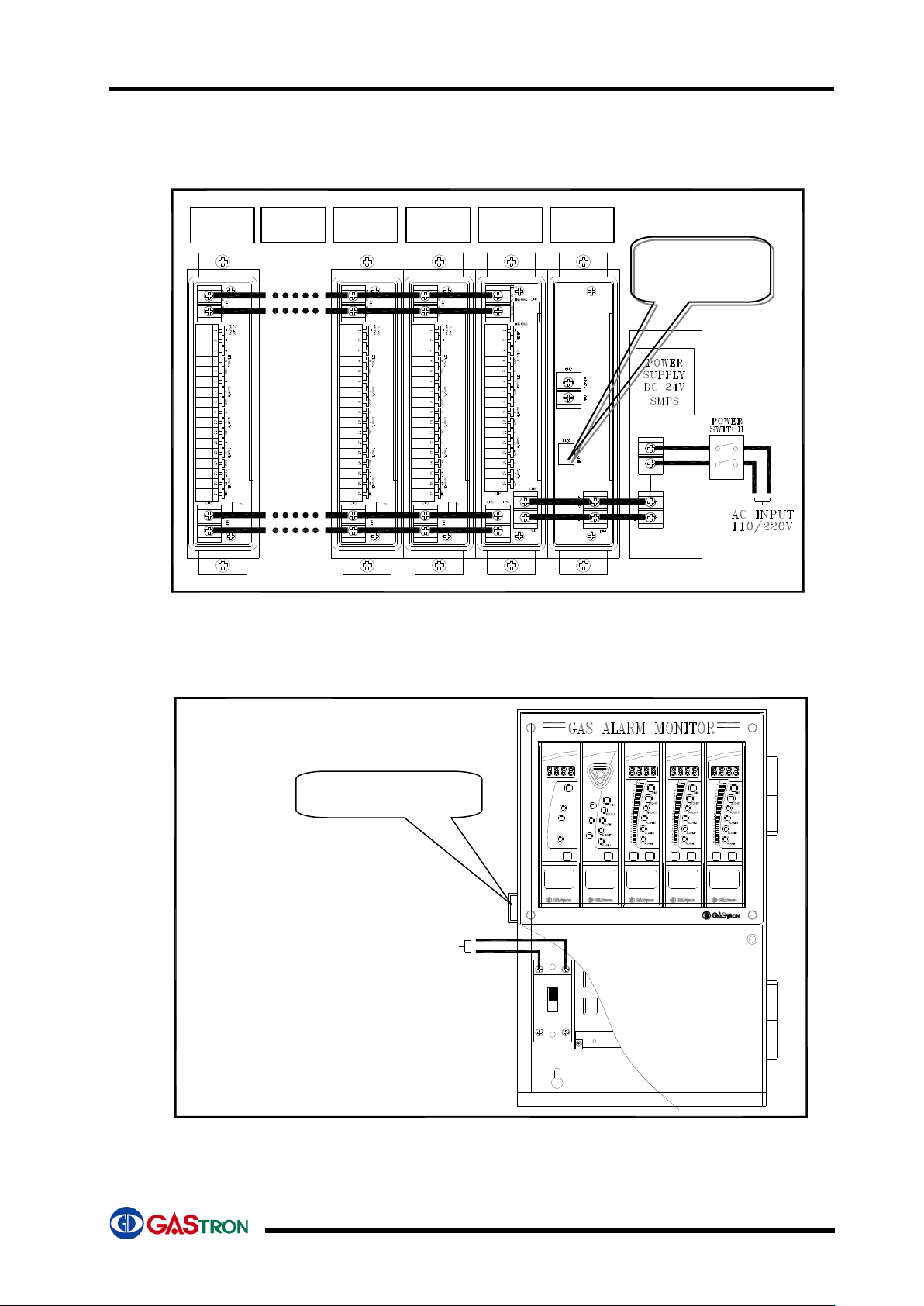
5. Terminal wiring diagram
5-1. POWER CONNECTION
5-1-1. Panel Mount Type
0V 24V
AC 110/220V
*. Power Unit is supplied only when using Battery. In case of no Power Unit, DC power (24V)
is directly connected from Power Supply to connector (CN6) of common unit. (Power Unit
is an option item.)
5-1-2. Wall Mount Type
RESETTEST
0
10
20
30
40
50
60
70
80
90
100
GTC200A CHANNEL
%LEL
GTC200A
COM-PC
COM-CH
BZ. STOP
GTC200A COMMON
RESET
BZ. STOP
GTC200A
BATT TROUBLE
BATT GOOD
BATT POWER
MAIN POWER
BATT TEST
VOLT
GTC200A POWER
GTC200A
RESETTEST
0
10
20
30
40
50
60
70
80
90
100
GTC200A CHANNEL
%LEL
GTC200A
RESETTEST
0
10
20
30
40
50
60
70
80
90
100
GTC200A CHANNEL
%LEL
GTC200A
Channel
Unit-#64
Channel
Unit-…
Channel
Unit-#2
Channel
Unit-#1
Common
Unit
Power
Unit
Release the fixing ring and open
front case. And then connect
electrical power to NFB, located at
left side in case
Operating voltage is AC110V or
220V and user can select voltage on
order. (Default voltage is AC220V)
Wall Mount Front Case
fixing ring
Back-up battery
(battery connection)
GTC-200A
15
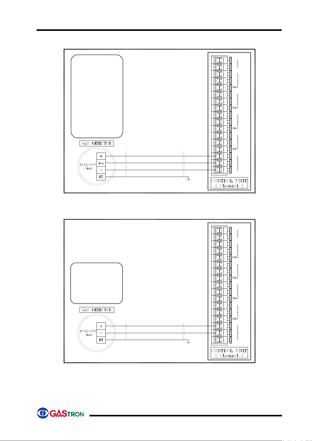
5-2. Gas Detector connection diagram (3Wire type)
11
10
8
9
7
-
mA
6
4
5
3
1
2
OUTPUT
4-20mA
-
+
SHILD
EARTH
ALARM3
( 경보3 )
ALARM2
( 경보2 )
SENSOR
(탐지기)
14
13
12
17
16
15
ALARM1
( 경보1 )
+
NO
TROUBLE
( 고 장 )
NC
NO
NC
NO
NC
NO
NC
Note) Please use CVVS or CVVSB 1.5sq↑ Shield Cable!
5-3. Gas Detector connection diagram (2Wire type)
11
10
8
9
7
-
mA
6
4
5
3
1
2
OUTPUT
4-20mA
-
+
SHILD
EARTH
ALARM3
( 경보3 )
ALARM2
( 경보2 )
SENSOR
(탐지기)
14
13
12
17
16
15
ALARM1
( 경보1 )
+
NO
TROUBLE
( 고 장 )
NC
NO
NC
NO
NC
NO
NC
Note) Please use CVVS or CVVSB 1.5sq↑ Shield Cable!
( Gas detector )
TS-1100Ex
TS-2000Ex
TS-2100 Series
TS-4000 Series
TS-4100 Series
TS-5100 Series
GTD-1000 Series
GTD-2000 Series
GTD-3000 Series
GIR-3000 Series
( Gas detector )
TS-1100Tx
TS-2000Tx
TS-3000 Series
TS-3100 Series
GTC-200A
16
6. How to use
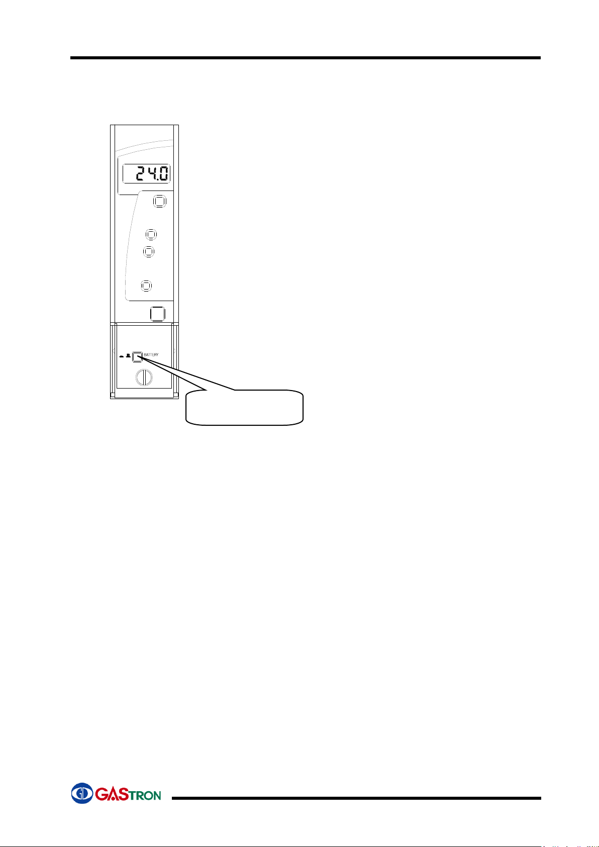
6-1. How to operate Power Unit
-. Voltage of main power is displayed on FND Digital Display.
-. If battery test key was pressed, the power is changed to Aux.
power (battery) and voltage of battery is displayed on FND
Digital Display.
-. If a back-up battery is not connected, battery trouble LED is
blinking (0.5 second interval).
-. If a back-up battery voltage is above 18V,the back-up battery
power is normal LED is on. Otherwise, battery trouble LED
is on.
Note) this unit is off when shipment.
Please turn on Aux. power switch after turned on main
power.
6-2. How to operate Common Unit
6-2-1. Buzzer alarm
-. gives short intermittent sound when receiving trouble signal from Channel Unit
-. gives long intermittent sound when receiving alarm signal from Channel Unit.
6-2-2. Trouble/alarm LED
-.These LEDs are turned on when receiving trouble or alarm signal from Channel
Unit
Alarm LED is flickering during alarm time.
6-2-3. Communication LED
-.COM-CH LED represents communication status between Common Unit and
Channel Unit. This LED is turned on at first communication (0.1 sec) with each
channel unit and turned off. If Common Unit can normally communicate with whole
pre-set channel units, this LED is continuously turning on. (Channel Unit Access
time: 0.1)
-.COM-PC LED is turned on once and immediately turned off when Common Unit
receives normally communication data from PC.
-. If SW1 (channel unit number) and SW2 (common unit address) are set under 1 in
common unit, COM-CH and COM-PC LEDs are flickering (0.5sec interval)
BATT TROUBLE
BATT GOOD
BATT POWER
MAIN POWER
BATT TEST
VOLT
GTC200A POWER
ON OFF POWER
Back-up battery
switch

GTC-200A
17
6-2-4. Buzzer Stop LED (BZ-STOP LED )
-. This LED is on when buzzer stops by pressing buzzer stop key in case of alarm
from Channel Unit (This LED is activated only when alarm type is set as Hold in
Channel Unit)
-. This LED is off when pressing buzzer stop key once again in Common or Channel
Unit.
6-2-5. Buzzer Stop & Reset Key
- In case of trouble or alarm on each channel unit, this key is used for stopping buzzer and
resetting
- Push once .... Buzzer sound stops and BZ-STOP LED is on.
- Push twice .... BZ-STOP LED is off and performs Reset function.
6-2-6. RS485 MODBUS communication Data
6-2-6-1. RS-485 communication Format
- Baudrate : 9600BPS
- Stop bit : 1 Stop
- Parity : Even parity
6-2-6-2. Gas density value (Analog input)
No
Function name
Address
Other
1
Channel-1 unit gas density value
30001
Channel address is
increased by 1 for
each channel unit.
2
Channel-2 unit gas density value
30002
3
Channel-3 unit gas density value
30xxx
6-2-6-3. Channel unit status Bit Data(Digital input contact reading Data)
Channel Unit
No
Function name
Address
Other
Channel-1
Unit
Alarm1 status Data
10001
8Bit is assigned
for each channel
unit
Alarm2 status Data
10002
Alarm3 status Data
10003
Trouble status Data
10004
Test status Data
10005
Spare Data
10006~10008
Channel-2
Unit
Alarm1 status Data
10009
8Bit is assigned
for each channel
unit
Alarm2 status Data
10010
Alarm3 status Data
10011
Trouble status Data
10012
Test status Data
10013
Spare Data
10014~10016
Channel-n
Unit
Status Data
10001+((n-1)*8) ~
10001+(((n-1)*8)+8)

GTC-200A
18
6-3. How to operate channel unit
6-3-1. Check of wiring
- Check wirings to operation power, gas detector, common unit and channel unit with
reference to Terminal wiring diagram (Section 5).
* Power supply is AC110/220V, 50/60Hz. (Please make sure to check power type before
turning on power)
6-3-2. Power ON
-.Turn power on after checking voltage of power supply.
-.Check power LED turned on at common unit and channel units.
-.Check “SELF” on FND at channel units.
6-3-3. Display of gas density
-.After power on of Channel Unit, “SELF” on FND at channel unit is flickering
about 15 seconds and the channel unit goes into measurement mode. If
the unit or gas detector has trouble, trouble signal occurs at this time.
-.Channel unit displays gas density received from gas detector as number
type on FND digital display.
-.Gas density is also displayed with 3 Color Bar Graphic LED
Under 1st Alarm density: Green color
Above 1st Alarm and under 2nd Alarm density: Orange color
Above 2nd Alarm density: Red color.
-. If there is no connection with gas detector or trouble at gas detector,
channel unit displays “Undr” with flickering (0.5 sec interval).
-. Trouble LED Lamp is also turned on.
-. Lowest round LED at 3 Color Bar Graphic LED is turned on with Red color.
-. If current value received from gas detector is 10% higher than
predetermined High scale value, “OuEr” is displayed with flickering (0.5
sec interval).
-. Highest round LED at 3 Color Bar Graphic LED is turned on with Redcolor.
-.If gas density is higher than alarm setting value, corresponding alarm is
activated after Alarm holding time.
-.Alarm LED Lamp is flickering (0.5 sec interval) during alarm holding time
and turned on after Alarm holding time.
-.Alarm Relay is ON after Alarm holding time.
-.If Alarm Latch Type is “on” mode, Alarm status and gas density value is
held at maximum value when alarm is activated. Gas density value held is
not automatically reset when real gas density is decreased below alarm
setting value and only can be reset by “Reset” key.
-.If Alarm Latch Type is “off” mode, Alarm is reset according to change of
measured gas density.
6-3-4. Program Data setting
-. Push “▲”, “▼” at the same time for over 2 seconds in gas density display
mode and goes into program data setting mode.
(During program setting mode, automatically return to density display
mode if there is no key input for 10 seconds.)
-. Firstly, “dP-S” (decimal point setting) is displayed.
-. Press “Func” key to go into decimal point setting mode.
-. If pressing “RESET” key, returns to density display mode.

GTC-200A
19
-. By pressing “▲” or “▼”, decimal point can be changed in 3 types.
-. Press “FUNC” key when desired decimal point is displayed to set the point
and go to next item
-. If pressing “RESET” key, returns to density display mode.
-. High Scale (Maximum display value of gas density) is displayed as “H-SL”
-. Press “Func” key to go into High scale setting mode
-. If pressing “RESET” key, returns to density display mode.
-. High Scale value was set when shipping from factory according to
domestic law
-.High Scale value can be changed according to measuring range with “▲”
or “▼”(increase or decrease).
-.If desired High scale value is displayed, press “FUNC” key to set the value
as High Scale and go to next item.
-. If pressing “RESET” key, returns to density display mode
-. This scale is set as same as detection range of gas detector at the factory.
Ex) when set Range as 100
4 mA.DC input ................... 0 Display
20 mA.DC input ................... 100 Display
-.SAD (compensating error from gas detector) setting message is displayed
as “SAd ”.
-. Press “Func” key to go into SAD value setting mode.
-. If pressing “RESET” key, returns to density display mode
-.When pressing “▲” or “▼” key, SAD value is increased or decreased (in
case of negative number, “-“ sign is added and displayed.
-.If desired SAD value is displayed, press “FUNC” key to set the value as
SAD and go to next item.
-.If pressing “RESET” key, returns to density display mode
ex) In case of setting SAD as 2 : if output error from gas detector is -2, the
display will be -2. In this case, User should compensate 2 (SAD setting
value) to display 0 on FND.
-. Channel Number setting message (setting recognition number of each
channel unit) is displayed as “CHno ”.
-. Press “Func” key to go into Channel Number setting mode..
-. If pressing “RESET” key, returns to density display mode
-.Common unit can check operation status of each channel unit with channel
number and this mode is to input each number (address) of channel unit.
When pressing “▲” or “▼” key, address no. of channel unit will be
increased or decreased.
-.If desired address number is displayed, press “FUNC” key to set the value
as Address NO. and go to next item (Alarm Reset Type function).
-.If pressing “RESET” key, returns to density display mode
-. If Channel No. was not inputted, Channel Unit and Common Unit can
not communicate with each other.
-. Please make sure to assign different number to Channel units.
6-3-5. Alarm Data setting
-.Push “Func” for over 2 seconds in gas density display mode and go into
alarm data setting mode.
-.(During alarm data setting mode, automatically return to density display

GTC-200A
20
mode if there is no key input for 10 seconds.)
-.Function to set Alarm Latch Type “LACH” is displayed.
-.Press “Func” to go into Alarm Latch Type setting mode.
-.If pressing “RESET” key, returns to density display mode
-.This step is for changing Alarm Reset Type. “ on” and “ oFF” are changed in
turns when pressing “▲”or “▼” key.
-.If desired Alarm Latch Type is displayed, press “FUNC” key to set the value
as Alarm Latch Type and go to next item.
- .If pressing “RESET” key, returns to density display mode
-. There are two kinds of Alarm Latch Type (“ on” and “ oFF”)
OFF mode is to automatically reset Alarm and ON mode is to reset alarm
manually.
-. Alarm1 value setting function (“AL-1”) is displayed.
-. Press “Func” key to go into Alarm1 value setting mode.
-.If pressing “RESET” key, returns to density display mode
-.This mode is to change Alarm1 setting value (up to High Scale value)
Alarm 1 value is increased or decreased by pressing “▲” or “▼” key.
-. If desired Alarm1 value is displayed, press “FUNC” to set the value as
Alarm1 and go to next item.
-.If pressing “RESET” key, returns to density display mode
-.Alarm Level was set when shipment according to density designated on
domestic law.
-. This mode is to set moving direction of Alarm1
“1H ” or “1L ” is displayed in turns when pressing “▲” or ▼” key.
-.“1H ” mode is to activate alarm when value is equal and bigger than alarm 1
setting value and “1L ” mode is to activate alarm when value is equal and
smaller than alarm 1 setting value.
-. If desired mode is displayed, press “FUNC” to set mode and go to next
item.
-.If pressing “RESET” key, returns to density display mode
-.Alarm Type was set at shipment (combustible: 1H & 2H & 3H / Oxygen: 3H
& 2H & 1L / Toxic: 1H & 2H & 3H Type).
-.This mode is to set alarm 1 dead band value and the value is increased or
decreased by pressing “▲” or ▼” key.
-. When Alarm1 is in “1H ”, alarm 1 is activated above the value (Alarm value
plus Dead band value) and is deactivated below the value ( Alarm value
minus Dead band value).
-. When Alarm1 is in “1L ”, alarm 1 is activated below the value (Alarm value
minus Dead band value) and is deactivated above the value ( Alarm value
plus Dead band value)
-. If desired alarm1 dead band value is displayed, press “FUNC” to set the
value and go to next item.
-.If pressing “RESET” key, returns to density display mode
-.This function is to give hysteresis value to removefrequent alarm on/off
around alarm setting value (this value is zero when shipment).
Ex) If alarm setting value is 20%LEL and Dead Band is 2%LEL, alarm is
activated at 22%LEL and deactivated at 18%LEL.
-.Alarm1 delay time setting function (“AL1t”) is displayed.
-.Press ”Func” key to go into alarm1 delay time setting mode.
-.If pressing “RESET” key, returns to density display mode
-. This function is to prevent malfunction by external shock or noise and
change of alarm1 delay time is increased or decreased by pressing “▲” or
“▼” key
-. If desired alarm1 delay time is displayed, press “FUNC” key to set alarm1
Other manuals for GTC-200A
1
Table of contents
Other GASTRON Receiver manuals


