Gates Radio Company BC-250GY-1 User manual


MODULATION TRANSFORMER INSTRUCTIONS
Please read these instructions before attempting to test
the modulation transformer in this transmitter.
The modulation transformer employed in this transmitter
may be of a type which will indicate unequal resistance
in the primary windings. An ohmmeter check of the wind-
ings may indicate that the transformer is defective;
whereas in reality, this is a normal reading and the
modulation transformer is performing normally.
In order to properly check this transformer outside of
the transmitter circuit, merely apply 117 volts, 60 cycle
a.c. to the secondary winding. Check the voltage on each
half of the primary winding. If the transformer is oper-
ating normally, then these voltages should be asproximately
equal.
Gates Radio Company
Quincy, Illinois
www.americanradiohistory.com
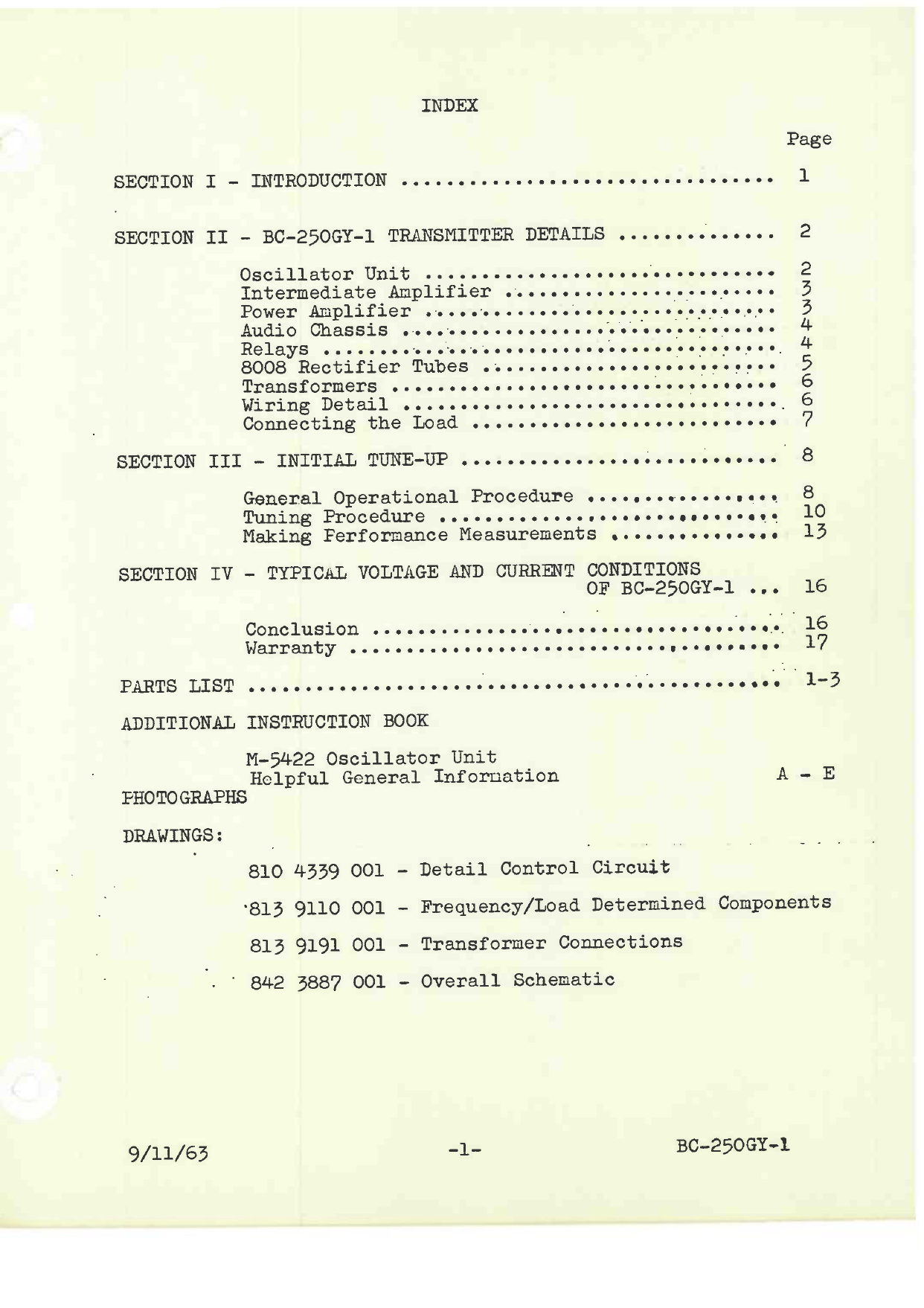
INDEX
Page
SECTION I - INTRODUCTION 1
SECTION II - BC-250GY-1 TRANSMITTER DETAILS 2
Oscillator Unit 2
Intermediate Amplifier 3
Power Amplifier 3
Audio Chassis 4
Relays 4
8008 Rectifier Tubes 5
Transformers 6
Wiring Detail 6
Connecting the Load 7
SECTION III - INITIAL TUNE-UP 8
General Operational Procedure 8
Tuning Procedure 10
Making Performance Measurements e 13
SECTION IV - TYPICAL VOLTAGE AND CURRENT CONDITIONS
OF BC-250GY-1 16
Conclusion 16
Warranty 17
PARTS LIST 1 -3
ADDITIONAL INSTRUCTION BOOK
M-5422 Oscillator Unit
Helpful General Information A - E
PHOTOGRAPHS
DRAWINGS:
810 4339 001 - Detail Control Circuit
.813 9110 001 - Frequency/Load Determined Components
813 9191 001 - Transformer Connections
842 3887 001 - Overall Schematic
9/11/63 -1- BC-250GY-1
www.americanradiohistory.com
Rated Power Output
Capable Power Output
Frequency Range
R.F. Output Impedance
Frequency StTbility
Carrier Shift
Audio Distortion
Audio Response
Residual Noise
Audio Input Impedance
Audio Input Level
Primary Supply
Power Consumption
Size
Weight and Cubage
Tubes:
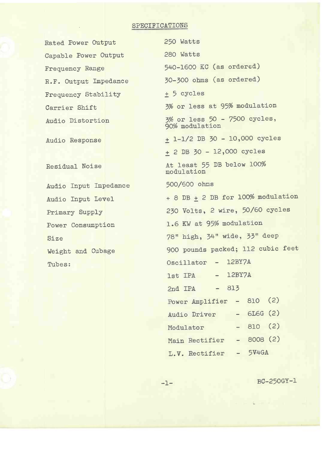
SPECIFICATIONS
250 Watts
280 Watts
540-1600 KC (as ordered)
30-300 ohms (as ordered)
+ 5 cycles
3% or less at 95% modulation
3% or less 50 - 7500 cycles,
90% modulation
+ 1-1/2 DB 30 - 10,000 cycles
+ 2 DB 30 - 12,000 cycles
At least 55 DB below 100%
modulation
500/600 ohms
+ 8 DB + 2 DB for 100% modulation
230 Volts, 2 wire, 50/60 cycles
1.6 KW at 95% modulation
high, 34" wide, 33" deep
78
900 pounds packed; 112 cubic feet
Oscillator - 12BY7A
1st IPA - 12BY7A
2nd IPA - 813
Power Amplifier - 810 (2)
Audio Driver
Modulator
Main Rectifier
L.V. Rectifier
-1-
6L6G (2)
810 (2)
8008 (2)
5V4GA
BC-250GY-1
www.americanradiohistory.com

SECTION
INTRODUCTION
The Gates BC-250GY Transmitter is a modern high fidelity
transmitter having every modern feature demanded by the modern
radio broadcasting station. When properly installed and main-
tained it will give years of trouble -free service.
The F.C.C. rated power of the BC-250GY transmitter is 250 watts
and is officially approved on the records of F.C.C. as a Gates
Radio Company Model BC-250GY Transmitter for amplitude modulation.
The radio frequency range of the BC-250GY transmitter is from
540 to 1600 KC. In each case specific frequency determining
components are supplied for operation of the transmitter on the
frequency specified when ordering. In certain rare situations
of critical antenna loading, the calculated frequency determining
components could be in error, making resonance and/or loading of
one or more circuits not complete. In such cases advise the
factory immediately.
The radio frequency output can be
load from 30 to 300 ohms, but can
components. It is also essential that
load impedance be specified. If this load impedance
active, such as with a direct fed tower,
will be required.
The radio transmitter unit is only one part of the station install-
ation. Each station has its own individual requirements dependent
on the plan of operation, location, etc. The Consulting Engineer
usually plans the transmitter and antenna system. At times, ad-
ditional special equipment will be desired. For this, consult
with the Gates Sales Engineering Staff, either the field repre-
sentative or at the factory office.
arranged to match a resistive
not do so with a single set of
in placing the order,
also is re-
compensating components
the
-1- BC-250GY-1
www.americanradiohistory.com

SECTION II
BC-250GY -1 TRANSMITTER DET^AILS
The following information on the BC-250GY transmitter pertains
to the general construction and operational detail surrounding
the transmitter itself. As in all modern transmitting equipment
it is best to look at the transmitter in its various sections
as pertaining to overall performance detail.
Oscillator Unit
The oscillator unit is located on the inside left of the cabinet,
facing the back, directly below the 813 intermediate amplifier
stage. This is the standard Gates M-5422 Oscillator Unit, using
vacuum crystals. It can be readily removed by loosening the four
mounting screws, and unplugging the connecting cable.
The operation of the M-5422 oscillator unit is explained in detail
in a separate section of this instruction book. The filament and
plate supply are obtained from a power supply on the audio driver
chassis; a part of this supply also is used for the modulator bias
voltage. A voltage divider delivers approximately 150 volts to
the M-5422 oscillator unit, and with this voltage the unit delivers
ample power to drive the following 813 stage.
The 813 stage is equipped with a grid current meter M8, mounted
on the 813 chassis. The M-5422 oscillator unit, which is oper-
ating when the filaments are on, can be tuned according to in-
structions for the maximum grid current reading on the meter M8.
This will be approximately 8 - 10 milliamperes without voltage on
the plate of the 813. The vacuum crystals have zero temperature
characteristics, and are operable on frequency as soon as the
tubes heat to normal emission. Any delay in setting the fre-
quency will be due to the requirements of the frequency monitor
having to reach a stable heat level. There are no gaps to set.
The crystals are normally received from the supplier after having
been calibrated in a M-5422 oscillator unit, and before shipment
are retested in the M-5422 oscillator unit supplied with the
transmitter. It can be anticipated that the frequency will be
within a very few cycles of the specified frequency, within the
range of adjustment of the frequency trimmer condensers.
9/11/63 -2- BC-250GY-1
www.americanradiohistory.com
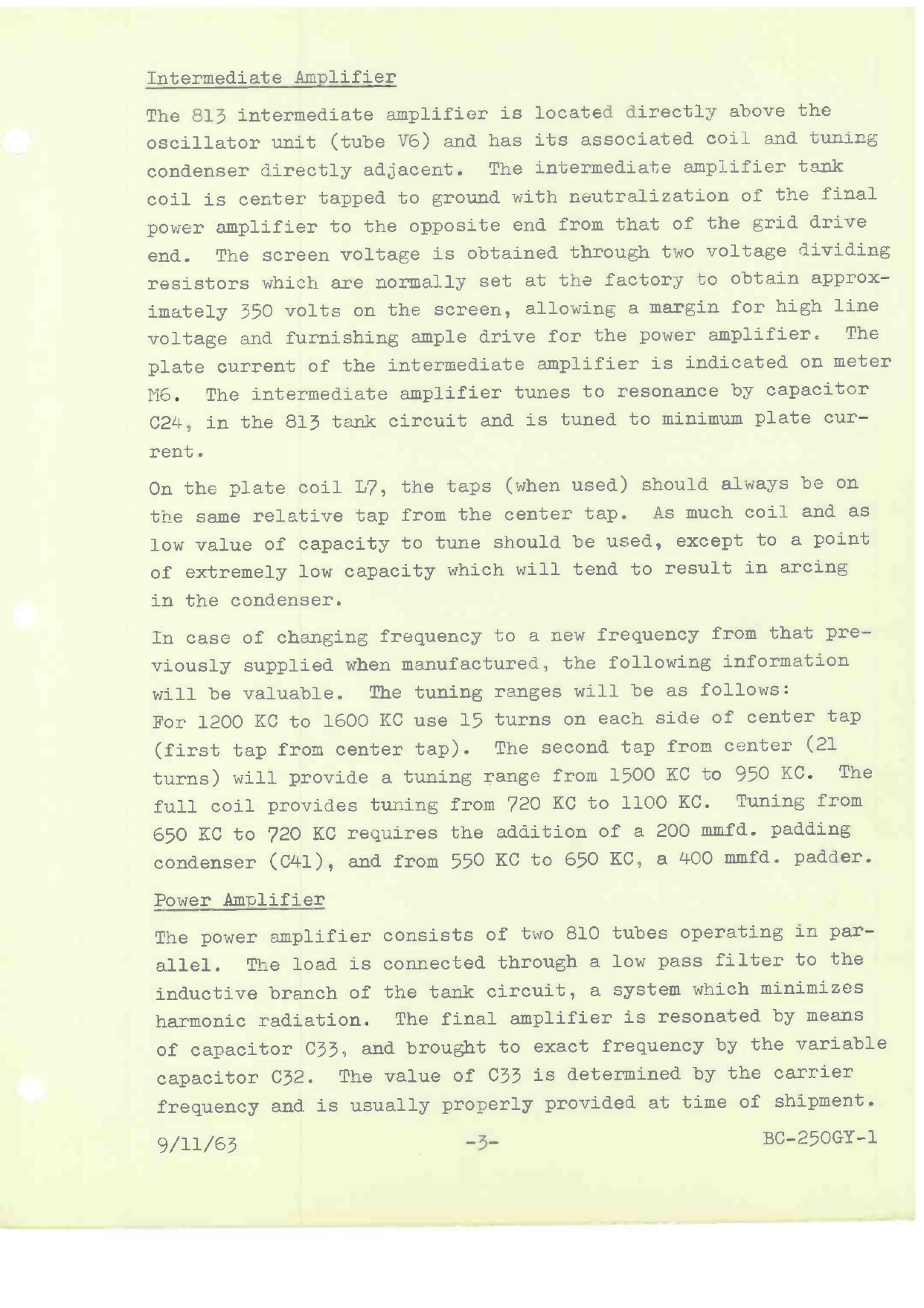
Intermediate Amplifier
The 813 intermediate amplifier is located directly above the
oscillator unit (tube V6) and has its associated coil and tuning
condenser directly adjacent. The intermediate amplifier tank
coil is center tapped to ground with neutralization of the final
power amplifier to the opposite end from that of the grid drive
end. The screen voltage is obtained through two voltage dividing
resistors which are normally set at the factory to obtain approx-
imately 350 volts on the screen, allowing a margin for high line
voltage and furnishing ample drive for the power amplifier. The
plate current of the intermediate amplifier is indicated on meter
M6. The intermediate amplifier tunes to resonance by capacitor
C24, in the 813 tank circuit and is tuned to minimum plate cur-
rent.
On the plate coil L7, the taps (when used) should always be on
the same relative tap from the center tap. As much coil and as
low value of capacity to tune should be used, except to a point
of extremely low capacity which will tend to result in arcing
in the condenser.
In case of changing frequency to a new frequency from that pre-
viously supplied when manufactured, the following information
will be valuable. The tuning ranges will be as follows:
For 1200 KC to 1600 KC use 15 turns on each side of center tap
(first tap from center tap). The second tap from center (21
turns) will provide a tuning range from 1500 KC to 950 KC. The
full coil provides tuning from 720 KC to 1100 KC. Tuning from
650 KC to 720 KC requires the addition of a 200 mmfd. padding
condenser (C41), and from 550 KC to 650 KC, a 400 mmfd. padder.
Power Amplifier
The power amplifier consists of two 810 tubes operating in par-
allel. The load is connected through a low pass filter to the
inductive branch of the tank circuit, a system which minimizes
harmonic radiation. The final amplifier is resonated by means
of capacitor C33, and brought to exact frequency by the variable
capacitor C32. The value of C33 is determined by the carrier
frequency and is usually properly provided at time of shipment.
9/11/63 -3- BC-250GY-1
www.americanradiohistory.com

In some instances of unusual loading conditions, particularly
very low impedance antennas, the value of tank padding conden-
ser C33, may be affected as applied to normal charts and if the
amplifier will not resonate with the load applied, it would be
the antenna and would only be in case of direct coupling, infor-
mation as to the antenna or loading characteristics should be
immediately supplied to the factory.
Audio Chassis
The audio chassis is the hinged chassis on the right hand of the
cabinet facing the rear and accommodates the push-pull 6L6G (1622)
Class A audio driver, the push-pull Class B 810 modulator tubes
on the top of the chassis and also accommodates the combination
oscillator-bias supply and its associates 5Ú4G tube and the
vacuum type time delay relay E6. The output of the 810 modulator
tubes terminates to modulation transformer T3, located in the
bottom of the cabinet. The plate voltage to the 6L6G tubes is
approximately 375 volts. The modulator tubes operate at the full
plate voltage of the main power supply.
For under- chassis servicing of the audio deck, it is only neces-
sary to remove the knurled thumb screws and this chassis hinges
back revealing all under-chassis wiring and components for fast
servicing where required. It should be noted that the oscillator
bias power supply is so constructed that 60 volts is taken from
the negative side of this supply to provide bias voltage for the
modulators, which is individually adjustable by bias resistors
R4 and R5.
Relays
The thermal operating filament time delay relay is mounted on the
audio chassis; the control element being connected across the
filaments of the 6L6G tubes. In case of breakage of the time
delay relay by accident or failure, to resume operation
a temporary expedient can be had by removing the time delay tube
from the audio chassis and placing a jumper between terminals
67 and 68. In this way there is no time delay action and the
overloads may trip from a cold start. This is usually due to
the bias voltage not having obtained full value. By waiting a
few seconds after the initial start no trouble will be encountered
Using the transmitter without the time delay tube, of course, is
not recommended and the above is mentioned only for servicing and
emergency procedure.
(4/11/63 -4- BC-250GY-1
www.americanradiohistory.com
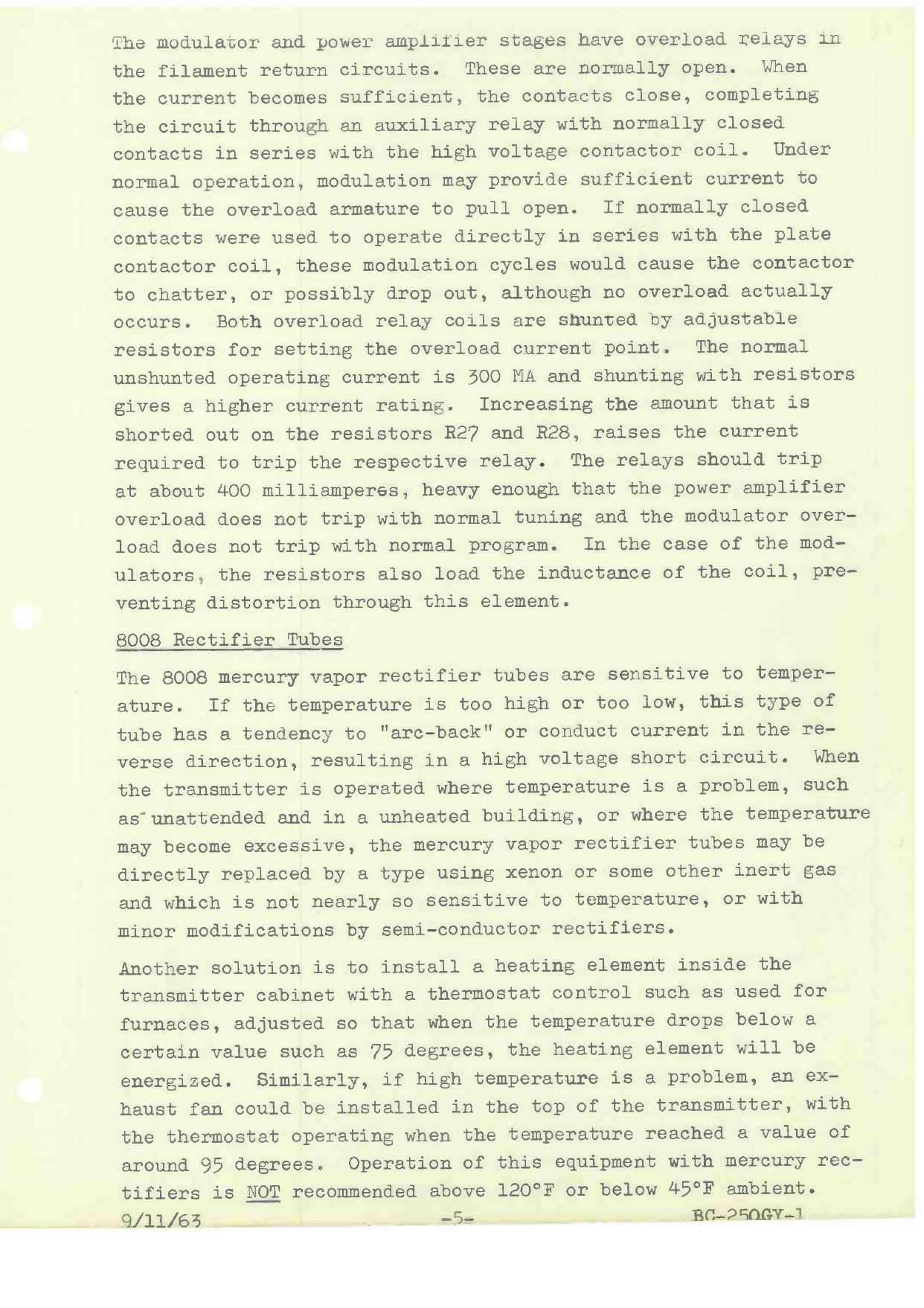
oduïator and sower ampliiier stages have overload relays in
the filament return circuits. These are normally open. When
the current becomes sufficient, the contacts close, completing
the circuit through an auxiliary relay with normally closed
contacts in series with the high voltage contactor coil. Under
normal operation, modulation may provide sufficient current to
cause the overload armature to pull open. If normally closed
contacts were used to operate directly in series with the plate
contactor coil, these modulation cycles would cause the contactor
to chatter, or possibly drop out, although no overload actually
occurs. Both overload relay coils are shunted by adjustable
resistors for setting the overload current point. The normal
unshunted operating current is 300 MA and shunting with resistors
gives a higher current rating. Increasing the amount that is
shorted out on the resistors R27 and R28, raises the current
required to trip the respective relay. The relays should trip
at about 400 milliamperes, heavy enough that the power amplifier
overload does not trip with normal tuning and the modulator over-
load does not trip with normal program. In the case of the mod-
ulators, the resistors also load the inductance of the coil, pre-
venting distortion through this element.
8008 Rectifier Tubes
The 8008 mercury vapor rectifier tubes are sensitive to temper-
ature. If the temperature is too high or too low, this type of
tube has a tendency to "arc-back" or conduct current in the re-
verse direction, resulting in a high voltage short circuit. When
the transmitter is operated where temperature is a problem, such
as-unattended and in a unheated building, or where the temperature
may become excessive, the mercury vapor rectifier tubes may be
directly replaced by a type using xenon or some other inert gas
and which is not nearly so sensitive to temperature, or with
minor modifications by semi-conductor rectifiers.
Another solution is to install a heating element inside the
transmitter cabinet with a thermostat control such as used for
furnaces, adjusted so that when the temperature drops below a
certain value such as 75 degrees, the heating element will be
energized. Similarly, if high temperature is a problem, an ex-
haust fan could be installed in the top of the transmitter, with
the thermostat operating when the temperature reached a value of
around 95 degrees. Operation of this equipment with mercury rec-
tifiers is NOT recommended above 120°F or below 45 °F ambient.
Q /11 /Fiji -5- Re-25flGY-1
www.americanradiohistory.com
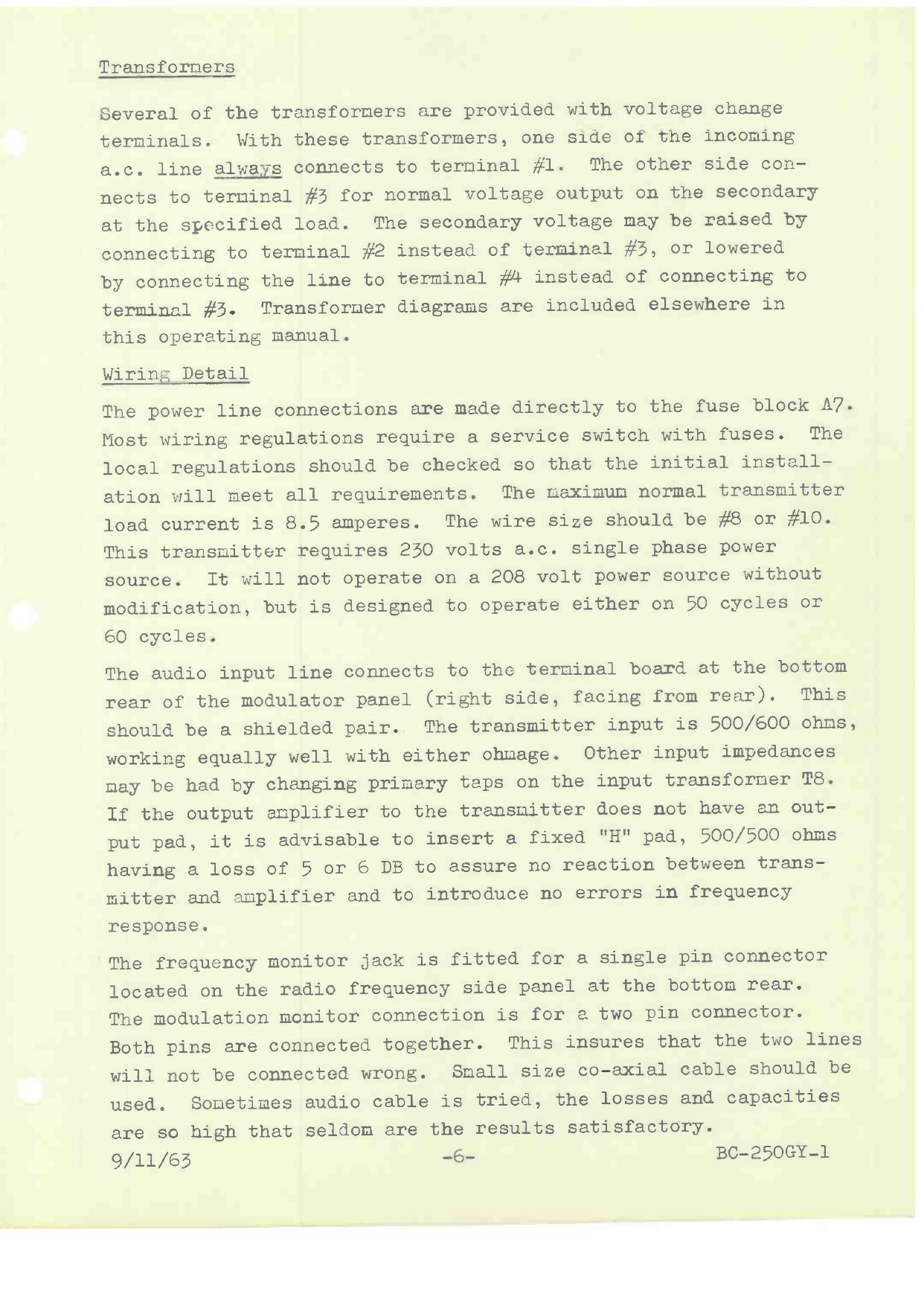
Transformers
Several of the transformers are provided with voltage change
terminals. With these transformers, one side of the incoming
a.c. line always connects to terminal #1. The other side con-
nects to terminal #3 for normal voltage output on the secondary
at the specified load. The secondary voltage may be raised by
connecting to terminal #2 instead of terminal #3, or lowered
by connecting the line to terminal ##4 instead of connecting to
terminal #3. Transformer diagrams are included elsewhere in
this operating manual.
Wiring Detail
The power line connections are made directly to the fuse block A7.
Most wiring regulations require a service switch with fuses. The
local regulations should be checked so that the initial install-
ation will meet all requirements. The maximum normal transmitter
load current is 8.5 amperes. The wire size should be #8 or #10.
This transmitter requires 230 volts a.c. single phase power
source. It will not operate on a 208 volt power source without
modification, but is designed to operate either on 50 cycles or
60 cycles.
The audio input line connects to the terminal board at the bottom
rear of the modulator panel (right side, facing from rear). This
should be a shielded pair. The transmitter input is 500/600 ohms,
working equally well with either ohmage. Other input impedances
may be had by changing primary taps on the input transformer T8.
If the output amplifier to the transmitter does not have an out-
put pad, it is advisable to insert a fixed "H" pad, 500/500 ohms
having a loss of 5 or 6 DB to assure no reaction between trans-
mitter and amplifier and to introduce no errors in frequency
response.
The frequency monitor jack is fitted for a single pin connector
located on the radio frequency side panel at the bottom rear.
The modulation monitor connection is for a two pin connector.
Both pins are connected together. This insures that the two lines
will not be connected wrong. Small size co-axial cable should be
used. Sometimes audio cable is tried, the losses and capacities
are so high that seldom are the results satisfactory.
9/11/63 -6- BC- 250GY-1
www.americanradiohistory.com

The transmitter cabinet should be well grounded. The cabinet
itself should be grounded by cable to meet underwriters' regu-
lations. The radio frequency output, which is the cabinet stud
on the top of the cabinet adjacent to the feedthru bowl, should
go to the radio system ground. At least a 2" copper strap is
recommended. In some installations, this lead might be dressed
down inside the transmitter, behind the side panel to the base,
and connecting to a strap from there to the system ground.
Connecting the Load
The coaxial or open wire transmission line or the direct coupled
antenna connects to the feedthru insulators on the top of the
transmitter. In the case of coaxial transmission line or open
wire transmission line, the ground portion of the transmission
line should be firmly secured to the top of the cabinet also, so
that the ground path will not have to travel through the tríns-
mitter cabinet. Where desired, the coaxial transmission line may
be brought up through the bottom of the cabinet at any number of
the convenient locations as will be quickly obvious to the install-
ing engineer's eye.
9/11/63 -7- BC-250GY-1
www.americanradiohistory.com

SECTION III
INITIAL TUNE-UP
General Operational Procedure
Before proceeding with the initial tune-up let us recheck the
necessary things to be done before any voltage is applied to any
portion of the transmitter. Briefly, check the following list:
1 - Proper line voltage to fuse block A?.
2 - Froper location of all tubes in the sockets.
3 - Froper termination of the antenna or dummy antenna
equipment.
4 - Removal of all tie -down straps and other materials
used for shipping purposes.
5 - A recheck to be sure components removed for shipment
have been installed properly.
6 - Complete check of the transmitter with a screwdriver
and wrench to be sure all bolts, screws and other
connections that could possibly work loose in shipment
have been brought down securely.
7 - Looking over all wiring for broken solder connections,
making sure that everything is secure.
8 - Making certain the transmitter is well grounded and
that the ground to the transmitter is tied to the
main ground of the antenna system. THIS IS VERY
IMPORTANT. AT LEAST 2" COPPER STRAP RECOMMENDED.
9 - Making certain that transformers with voltage
correction taps have one side of the supply line
connecting to terminal #1.
10 - Making sure audio wiring has been properly shielded
and that the shields have been properly grounded,
and that no input wire runs in the same cable as an
output wire or a power cable.
In case the transmitter is located on the upper floor of a
building, particular attention must be paid to grounding of
the equipment. Additional ground busses and elimination of
varied ground potentials is highly important for good per-
formance and low noise.
With the transmitter ready to operate, the service switch is
closed and power supplied to the transmitter. Pressing the
"Filament ON" switch Sl, lights the tube filaments and the
power supply for the M-5422 oscillator unit. The oscillator
unit is tuned according to the directions given in the instruc-
tions for this unit. When the transmitter has been factory
9/11/63 -8- BC-250GY -1
www.americanradiohistory.com
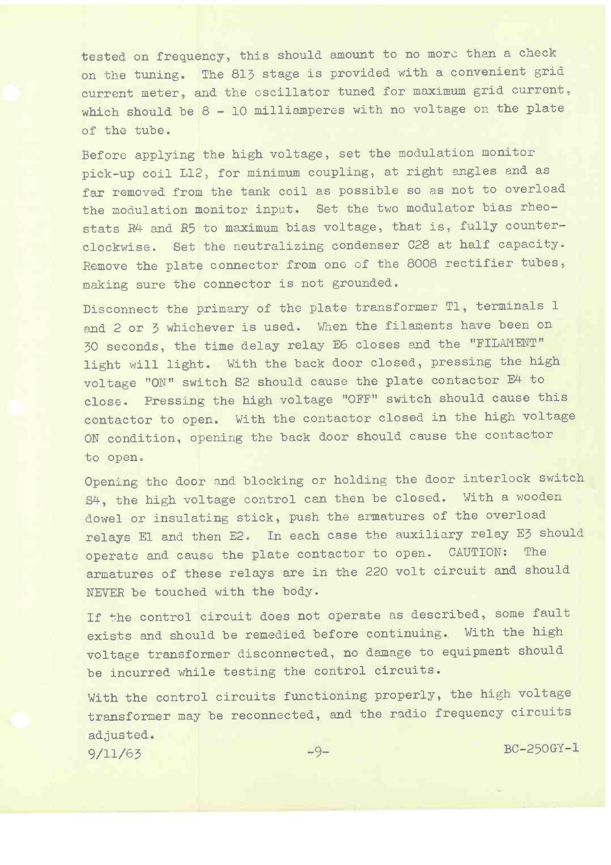
tested on frequency, this should amount to no more than a check
on the tuning. The 813 stage is provided with a convenient grid
current meter, and the oscillator tuned for maximum grid current,
which should be 8 - 10 milliamperes with no voltage on the plate
of the tube.
Before applying the high voltage, set the modulation monitor
pick -up coil L12, for minimum coupling, at right angles and as
far removed from the tank coil as possible so as not to overload
the modulation monitor input. Set the two modulator bias rheo-
stats R4 and R5 to maximum bias voltage, that is, fully counter-
clockwise. Set the neutralizing condenser C28 at half capacity.
Remove the plate connector from one of the 8008 rectifier tubes,
making sure the connector is not grounded.
Disconnect the primary of the plate transformer Tl, terminals 1
and 2 or 3 whichever is used. When the filaments have been on
30 seconds, the time delay relay E6 closes and the "FILAMENT"
light will light. With the back door closed, pressing the high
voltage "ON" switch S2 should cause the plate contactor E4 to
close. Pressing the high voltage "OFF" switch should cause this
contactor to open. With the contactor closed in the high voltage
ON condition, opening the back door should cause the contactor
to open.
Opening the door and blocking or holding the door interlock switch
S4, the high voltage control can then be closed. With a wooden
dowel or insulating stick, push the armatures of the overload
relays El and then E2. In each case the auxiliary relay E3 should
operate and cause the plate contactor to open. CAUTION: The
armatures of these relays are in the 220 volt circuit and should
NEVER be touched with the body.
If the control circuit does not operate as described, some fault
exists and should be remedied before continuing. With the high
voltage transformer disconnected, no damage to equipment should
be incurred while testing the control circuits.
With the control circuits functioning properly, the high voltage
transformer may be reconnected, and the ridio frequency circuits
adjusted.
9/11/63 -9- BC-250GY-1
www.americanradiohistory.com
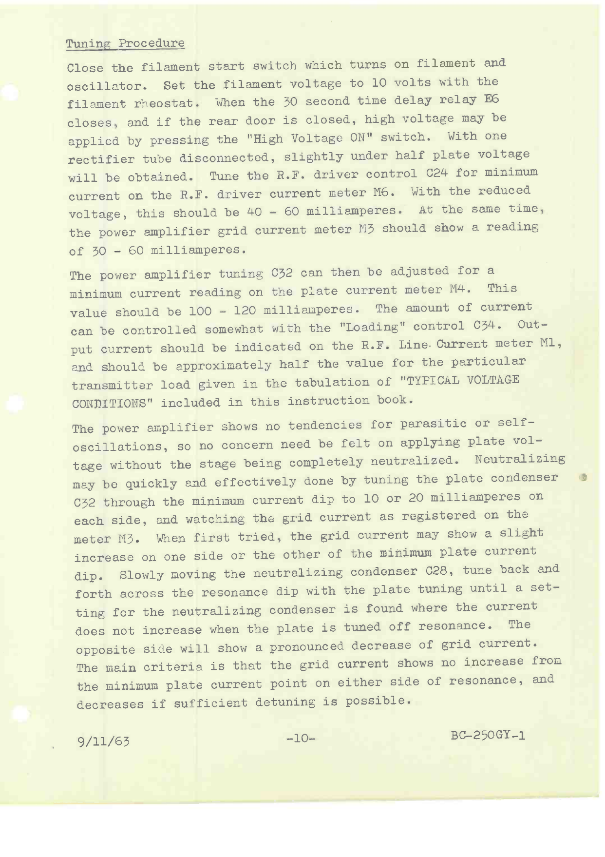
Tuning Procedure
Close the filament start switch which turns on filament and
oscillator. Set the filament voltage to 10 volts with the
filament rheostat. When the 30 second time delay relay E6
closes, and if the rear door is closed, high voltage may be
applied by pressing the "High Voltage ON" switch. With one
rectifier tube disconnected, slightly under half plate voltage
will be obtained. Tune the R.F. driver control C24 for minimum
current on the R.F. driver current meter M6. With the reduced
voltage, this should be 40 - 60 milliamperes. At the same time,
the power amplifier grid current meter M3 should show a reading
of 30 - 60 milliamperes.
The power amplifier tuning 032 can then be adjusted for a
minimum current reading on the plate current meter M4. This
value should be 100 - 120 milliamperes. The amount of current
can be controlled somewhat with the "Loading" control 034. Out-
put current should be indicated on the R.F. Line.Current meter Ml,
and should be approximately half the value for the particular
transmitter load given in the tabulation of "TYPICAL VOLTAGE
CONDITIONS" included in this instruction book.
The power amplifier shows no tendencies for parasitic or self -
oscillations, so no concern need be felt on applying plate vol-
tage without the stage being completely neutralized. Neutralizing
may be quickly and effectively done by tuning the plate condenser
C32 through the minimum current dip to 10 or 20 milliamperes on
each side, and watching the grid current as registered on the
meter M3. When first tried, the grid current may show a slight
increase on one side or the other of the minimum plate current
dip. Slowly moving the neutralizing condenser C28, tune back and
forth across the resonance dip with the plate tuning until a set-
ting for the neutralizing condenser is found where the current
does not increase when the plate is tuned off resonance. The
opposite side will show a pronounced decrease of grid current.
The main criteria is that the grid current shows no increase from
the minimum plate current point on either side of resonance, and
decreases if sufficient detuning is possible.
. 9/11/63 -10- BC-250GY-1
www.americanradiohistory.com
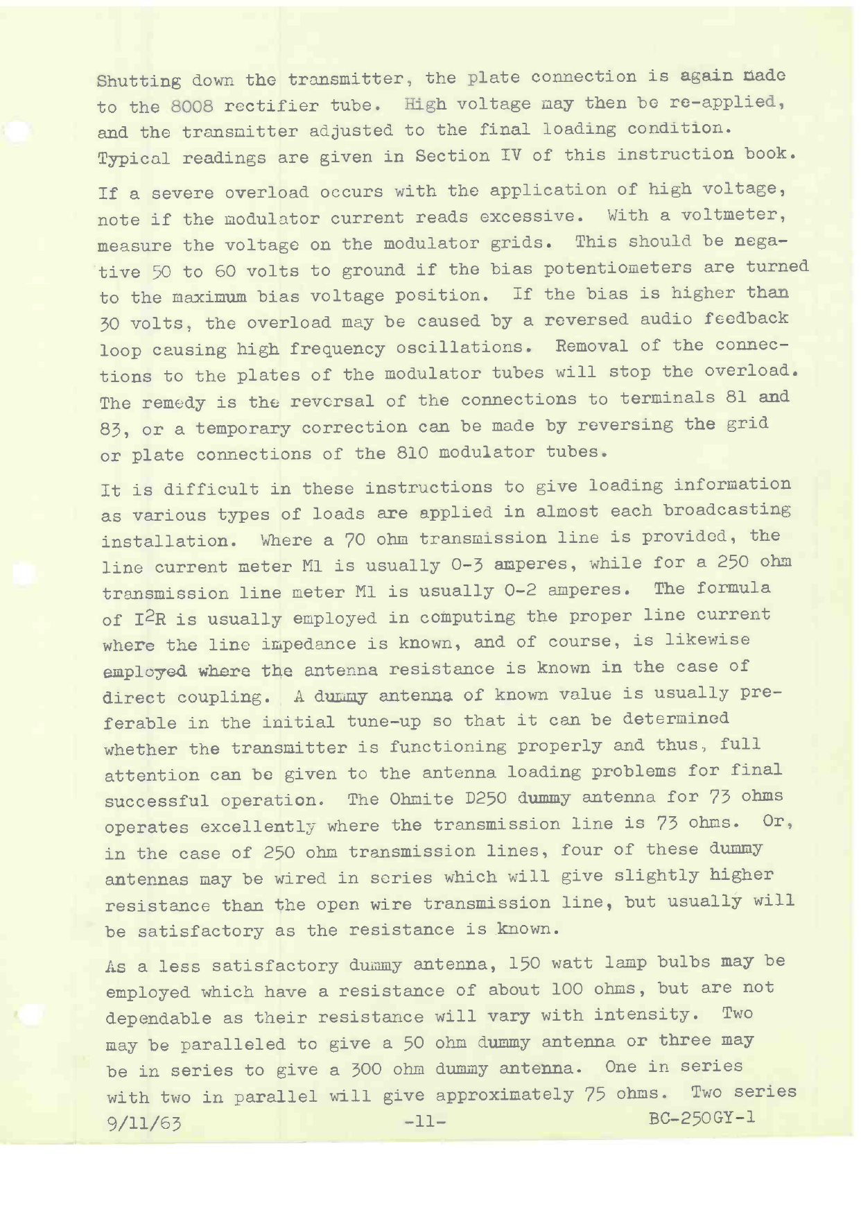
Shutting down the transmitter, the plate connection is again nade
to the 8008 rectifier tube. High voltage may then be re-applied,
and the transmitter adjusted to the final loading condition.
Typical readings are given in Section IV of this instruction book.
If a severe overload occurs with the application of high voltage,
note if the modulator current reads excessive. With a voltmeter,
measure the voltage on the modulator grids. This should be nega-
tive 50 to 60 volts to ground if the bias potentiometers are turned
to the maximum bias voltage position. If the bias is higher than
30 volts, the overload may be caused by a reversed audio feedback
loop causing high frequency oscillations. Removal of the connec-
tions to the plates of the modulator tubes will stop the overload.
The remedy is the reversal of the connections to terminals 81 and
83, or a temporary correction can be made by reversing the grid
or plate connections of the 810 modulator tubes.
It is difficult in these instructions to give loading information
as various types of loads are applied in almost each broadcasting
installation. Where a 70 ohm transmission line is provided, the
line current meter Ml is usually 0-3 amperes, while for a 250 ohm
transmission line meter Ml is usually 0-2 amperes. The formula
of I2R is usually employed in computing the proper line current
where the line impedance is known, and of course, is likewise
employed whrlre the antenna resistance is known in the case of
direct coupling. A dummy antenna of known value is usually pre-
ferable in the initial tune -up so that it can be determined
whether the transmitter is functioning properly and thus, full
attention can be given to the antenna loading problems for final
successful operation. The Ohmite D250 dummy antenna for 73 ohms
operates excellently where the transmission line is 73 ohms. Or,
in the case of 250 ohm transmission lines, four of these dummy
antennas may be wired in series which will give slightly higher
resistance than the open wire transmission line, but usually will
be satisfactory as the resistance is known.
As a less satisfactory dummy antenna, 150 watt lamp bulbs may be
employed which have a resistance of about 100 ohms, but are not
dependable as their resistance will vary with intensity. Two
may be paralleled to
be in series to give
with two in parallel
9/11/63
give a 50 ohm dummy antenna or three may
a 300 ohm dummy antenna. One in series
will give approximately 75 ohms. Two series
-11- BC-250GY-1
www.americanradiohistory.com

connected in series with two parallel connected will give approx-
imately 250 ohms. As light bulbs are highly reactive, the actual
load will be considerably removed from the proper condition
but will serve to allow a good preliminary checkup. As the
power amplifier tank circuit is directly affected by the load,
it is well to discount this in the subject of loading conditions.
The power amplifier tank is usually provided with a padding capac-
ity C33 in addition to the variable tuning capacity C32. The
tank capacity and the coupling capacities C34 and C35 determine
the harmonic suppression, a chart of recommended values for
various frequencies and common loadings is given elsewhere in
this instruction book. Special loading conditions may require
modification, and frequently the addition of a series condenser.
In this latter case, the condenser is between the line coil L11
and meter Ml. The proper loading of the transmitter to the
particular condition must be admitted as more or less on a cut-
and -try basis, adjusting C34 and the taps on coil 1,11; maintaining
the final power amplifier in complete resonance will eventually
produce the desired results where the load is not below 30 ohms
or exceeds 300 ohms. Final current into the line load on the
formula I2R is, of course, the answer to the correctness of the
load. The efficiency of the BC-250GY transmitter is 70% and
seldom over 75%. It should be remembered that efficiency is
measured into a known load,.and preferably a resistive load
designed for radio frequency operation. It should also be re-
membered that a radio transmitter of standard construction is
not normally inefficient when, of course, properly adjusted and
tuned. Thus, lack of efficiency in operation can usually always
be attributed to lack of proper loading conditions to the trans-
mitter itself, which is usually indicated by unbalanced line
currents in the case of a transmission line, and of course, can
be checked by making sure ground connections to the transmitter
are well nade directly to the radiating system of the antenna.
Abnormally high efficiency is quite frequently found to be in
the antenna system. This may be checked if a dummy antenna of
equavalent resistance is substituted for the line or antenna.
It may be found that the line current meter is measuring reactive
currents, which would give a false impression of efficiency.
9/11/63 -12- BC-250GY -1
www.americanradiohistory.com
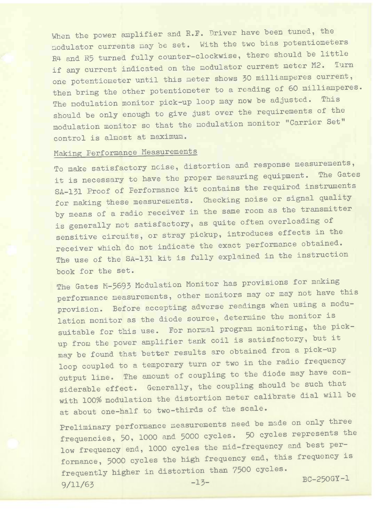
When the power amplifier and R.F. Driver have been tuned, the
modulator currents may be set. With the two bias potentiometers
R4 and R5 turned fully counter -clockwise, there should be little
if any current indicated on the modulator current meter M2. Turn
one potentiometer until this meter shows 30 milliamperes current,
then bring the other potentiometer to a reading of 60 milliamperes.
The modulation monitor pick-up loop may now be adjusted. This
should be only enough to give just over the requirements of the
modulation monitor so that the modulation monitor "Carrier Set"
control is almost at maximum.
Making Performance Measurements
To make satisfactory ncise, distortion and response measurements,
it is necessary to have the proper measuring equipment. The Gates
SA-131 Proof of Performance kit contains the required instruments
for making these measurements. Checking noise or signal quality
by means of a radio receiver in the sane room as the transmitter
is generally not satisfactory, as quite often overloading of
sensitive circuits, or stray pickup, introduces effects in the
receiver which do not indicate the exact performance obtained.
The use of the SA-131 kit is fully explained in the instruction
book for the set.
The Gates M-5693 Modulation Monitor has provisions for making
performance measurements, other monitors may or may not have this
provision. Before accepting adverse readings when using a modu-
lation monitor as the diode source, determine the monitor is
suitable for this use. For normal program monitoring, the pick-
up from the power amplifier tank coil is satisfactory, but it
may be found that better results are obtained from a pick -up
loop coupled to a temporary turn or two in the radio frequency
output line. The amount of coupling to the diode may have con-
siderable effect. Generally, the coupling should be such that
with 100% modulation the distortion meter calibrate dial will be
at about one -half to two-thirds of the scale.
Preliminary performance measurements need be made on only three
frequencies, 50, 1000 and 5000 cycles. 50 cycles represents the
low frequency end, 1000 cycles the mid-frequency and best per-
formance, 5000 cycles the high frequency end, this frequency is
frequently higher in distortion than 7500 cycles.
9/11/63 -13- BC- 250GY-1
www.americanradiohistory.com

Distortion readings on these three frequencies can be taken.
Then with the 50 cycle frequency, hold the back door interlock,
apply the high voltage, and set for the distortion reading. Then
adjust the bias potentiometers for distortion below 3%, but not
necessarily the minimum possible distortion, as this adjustment
may increase the noise and distortion on other frequencies.
After this adjustment is made, recheck the other two frequencies
and the noise level. When setting the bias potentiometers, ex-
treme caution should be used, with preferably a second person
helping. If the performance is within specifications, a complete
frequency run may be made.
In case the distortion or noise is out of specifications, several
remedies may be tried. Different tubes may be tried, particularly
the 6L6G audio driver and 810 modulator tubes. Because a tube is
new out of a carton is no guarantee that it has not received some
damage in shipping.
The polarity of the modulation tránsformer may be reversed by
inter-changing the two modulator tube leads on the primary of the
transformer and connecting whichever way gives the best results
for all frequencies. The modulator grid connections could be
interchanged, and doing this requires that the feedback also be
reversed. Both reversals, that is, the driver and modulator
could be tried simultaneously. In each case, the modulator
bias should be adjusted for 50 cycle distortion below 3% if obtain-
able.
Some noise improvement can be obtained by proper phasing of the
audio system by the means just outlined so some cancellation is
obtained between the audio and radio frequency sections, but this
can easily upset the distortion performance. Considerable noise
variations can be encountered in the tuning of the radio frequency
part of the transmitter. Normally, the best noise reading will be
obtained when the 813 driver stage is tuned to the minimum plate
current. The power amplifier neutralizing has some effect. If
the radio frequency drive is low in any of the radio frequency
stages, some grid modulation is fed through to cause the noise.
The phasing mentioned is that the noise generated in the audio
section is opposed to.that generated in the radio section result-
ing in cancellation with the residual being the difference of
the two magnitudes. BC-250GY -1
9/11/63 -14-
www.americanradiohistory.com
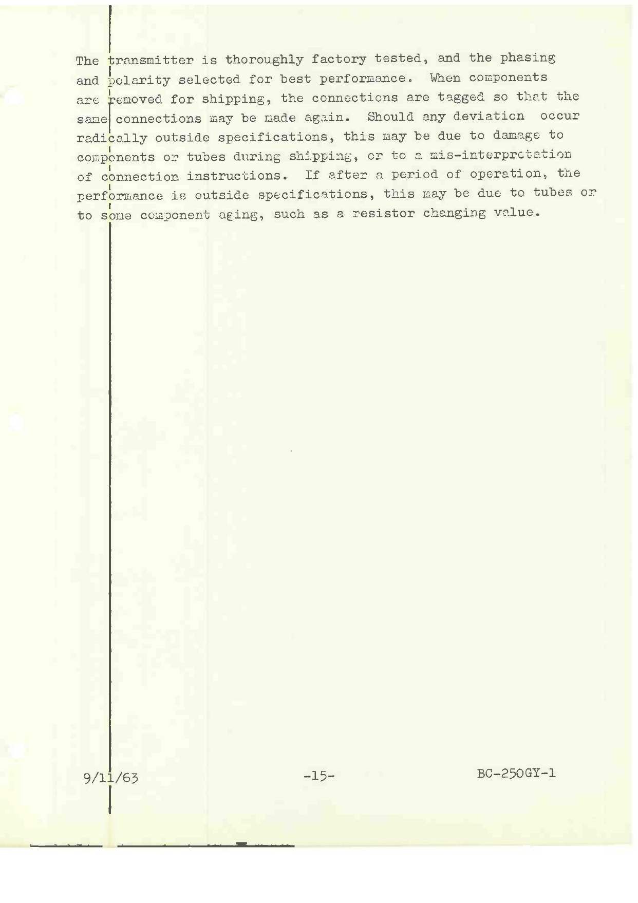
The transmitter is thoroughly factory tested, and the phasing
and polarity selected for best performance. When components
are removed for shipping, the connections are tagged so that the
sane connections may be made again. Should any deviation occur
radically outside specifications, this may be due to damage to
components or tubes during shipping, or to a mis-interpretation
of connection instructions. If after a period of operation, the
performance is outside specifications, this may be due to tubes or
to some component aE:ing, such as a resistor changing value.
9/11/63 -5- BC-250G-1
www.americanradiohistory.com
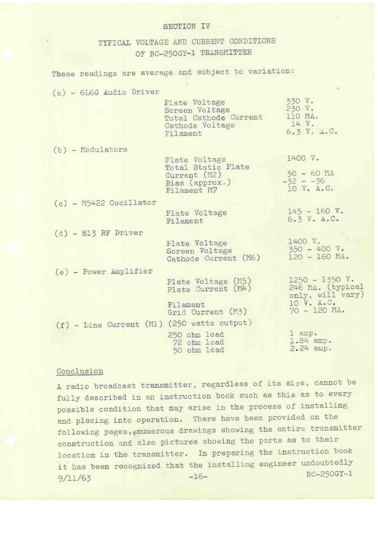
SECTION IV
TYPICAL VOLTAGE AND CURRENT CONDITIONS
OF BC-250GY-1 TRANSMITTER
These readings are average and subject to variation:
(a) - 6L6G Audio Driver
(b) - Modulators
(c) - M5422 Oscillator
(d) - 813 RF Driver
(e) - Power Amplifier
Plate Voltage
Screen Voltage
Total Cathode Current
Cathode Voltage
Filament
Plate Voltage
Total Static Plate
Current (M2)
Bias (approx.)
Filament M7
Plate Voltage
Filament
Ilate Voltage
Screen Voltage
Cathode Current (M6)
Plate Voltage (M5
Plate Current (M4
Filament
Grid Current (M3)
(f) - Line Current (M1) (250 watts output)
250 ohm load
72 ohm load
50 ohm load
330 V.
230 V.
110 MA.
14 V.
6.3 V. A. C.
1400 V.
50 - 60 MA
-32 - -36
10 V. A.C.
145 - 160 V.
6.3 V. A.C.
1400 V.
350 - 400 V.
120 - 160 MA.
1250 - 1350 V.
246 MA. (typical
only, will vary)
10 V. A.C.
70 - 120 MA.
1 amp.
1.84 amp.
2.24 amp.
Conclusion
A radio broadcast transmitter, regardless of its size, cannot be
fully described in an instruction book such as this as to every
possible condition that may arise in the process of installing
and placing into operation. There have been provided on the
following pages, »numerous drawings showing the entire transmitter
construction and also pictures showing the parts as to their
location in the transmitter. In preparing the instruction book
it has been recognized that the installing engineer undoubtedly
9/11/63 -16- BC-250GY-1
www.americanradiohistory.com
Table of contents
Other Gates Radio Company Transmitter manuals

Popular Transmitter manuals by other brands

Evikon
Evikon PluraSens E2227 user manual

Alligator
Alligator KC-9512 instruction manual

Sailor
Sailor T2031 Instruction book

Extron electronics
Extron electronics DVI 201 A D Tx/Rx Specification sheet

Cardin Elettronica
Cardin Elettronica TXQPRO486 quick start guide

Pfeiffer Vacuum
Pfeiffer Vacuum RPT 100 operating instructions


