Vega VEGABAR 82 User manual

Operating Instructions
Pressure transmitter with ceramic
measuring cell
VEGABAR 82
Modbus and Levelmaster protocol
Document ID: 46294

2
Contents
VEGABAR 82 • Modbus and Levelmaster protocol
46294-EN-171120
Contents
1 About this document ............................................................................................................... 4
1.1 Function ........................................................................................................................... 4
1.2 Target group ..................................................................................................................... 4
1.3 Symbols used................................................................................................................... 4
2 For your safety ......................................................................................................................... 5
2.1 Authorised personnel ....................................................................................................... 5
2.2 Appropriate use................................................................................................................ 5
2.3 Warning about incorrect use............................................................................................. 5
2.4 General safety instructions............................................................................................... 5
2.5 EU conformity................................................................................................................... 6
2.6 Permissible process pressure .......................................................................................... 6
2.7 NAMUR recommendations .............................................................................................. 6
2.8 Installation and operation in the USA and Canada ........................................................... 6
2.9 Environmental instructions ............................................................................................... 7
3 Product description ................................................................................................................. 8
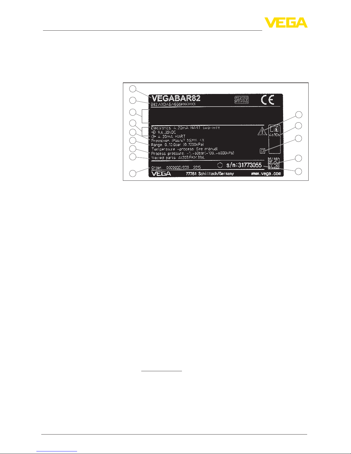
3.1 Conguration.................................................................................................................... 8
3.2 Principle of operation........................................................................................................ 9
3.3 Supplementary cleaning procedures.............................................................................. 14
3.4 Packaging, transport and storage................................................................................... 15
3.5 Accessories and replacement parts ............................................................................... 15
4 Mounting................................................................................................................................. 17
4.1 General instructions ....................................................................................................... 17
4.2 Ventilation and pressure compensation.......................................................................... 18
4.3 Process pressure measurement..................................................................................... 21
4.4 Level measurement........................................................................................................ 23
4.5 External housing ............................................................................................................ 24
5 Connecting to power supply and bus system .................................................................... 25
5.1 Preparing the connection ............................................................................................... 25
5.2 Connecting..................................................................................................................... 26
5.3 Wiring plan ..................................................................................................................... 27
5.4 External housing with version IP 68 (25 bar)................................................................... 29
5.5 Switch-on phase............................................................................................................. 31
6 Set up the sensor with the display and adjustment module ............................................. 32
6.1 Insert display and adjustment module............................................................................ 32
6.2 Adjustment system......................................................................................................... 33
6.3 Measured value indication.............................................................................................. 34
6.4 Parameter adjustment - Quick setup .............................................................................. 35
6.5 Parameter adjustment - Extended adjustment................................................................ 35
6.6 Saving the parameterisation data................................................................................... 47
7 Setting up sensor and Modbus interface with PACTware.................................................. 48
7.1 Connect the PC.............................................................................................................. 48
7.2 Parameter adjustment .................................................................................................... 49
7.3 Set instrument address .................................................................................................. 51
8 Diagnosis, asset management and service ........................................................................ 52
8.1 Maintenance .................................................................................................................. 52

3
Contents
VEGABAR 82 • Modbus and Levelmaster protocol
46294-EN-171120
8.2 Cleaning - hygienic connection with compression nut .................................................... 52
8.3 Diagnosis memory ......................................................................................................... 53
8.4 Asset Management function........................................................................................... 53
8.5 Rectify faults................................................................................................................... 57
8.6 Exchange process module on version IP 68 (25 bar) ..................................................... 57
8.7 Exchanging the electronics module................................................................................ 58
8.8 Software update ............................................................................................................. 59
8.9 How to proceed if a repair is necessary.......................................................................... 59
9 Dismount................................................................................................................................. 60
9.1 Dismounting steps.......................................................................................................... 60
9.2 Disposal ......................................................................................................................... 60
10 Supplement ............................................................................................................................ 61
10.1 Technical data ................................................................................................................ 61
10.2 Basics Modbus............................................................................................................... 73
10.3 Modbus register ............................................................................................................. 75
10.4 Modbus RTU commands ............................................................................................... 77
10.5 Levelmaster commands ................................................................................................. 80
10.6 CongurationoftypicalModbushosts ........................................................................... 84
10.7 Calculation of the total deviation..................................................................................... 88
10.8 Practical example........................................................................................................... 89
10.9 Dimensions .................................................................................................................... 91
10.10 Industrial property rights............................................................................................... 100
10.11 Trademark .................................................................................................................... 100
Safety instructions for Ex areas
TakenoteoftheExspecicsafetyinstructionsforExapplications.
These instructions are attached as documents to each instrument
with Ex approval and are part of the operating instructions manual.
Editing status: 2017-11-14

4
1 About this document
VEGABAR 82 • Modbus and Levelmaster protocol
46294-EN-171120
1 About this document
1.1 Function
This operating instructions manual provides all the information you
need for mounting, connection and setup as well as important instruc-
tionsformaintenance,faultrectication,theexchangeofpartsand
the safety of the user. Please read this information before putting the
instrument into operation and keep this manual accessible in the im-
mediate vicinity of the device.
1.2 Target group
This operating instructions manual is directed to trained personnel.
Thecontentsofthismanualmustbemadeavailabletothequalied
personnel and implemented.
1.3 Symbols used
Document ID
This symbol on the front page of this instruction refers to the Docu-
ment ID. By entering the Document ID on www.vega.com you will
reach the document download.
Information, tip, note
This symbol indicates helpful additional information.
Caution: If this warning is ignored, faults or malfunctions can result.
Warning: If this warning is ignored, injury to persons and/or serious
damage to the instrument can result.
Danger: If this warning is ignored, serious injury to persons and/or
destruction of the instrument can result.
Ex applications
This symbol indicates special instructions for Ex applications.
• List
The dot set in front indicates a list with no implied sequence.
→ Action
This arrow indicates a single action.
1 Sequence of actions
Numbers set in front indicate successive steps in a procedure.
Battery disposal
This symbol indicates special information about the disposal of bat-
teries and accumulators.

5
2 For your safety
VEGABAR 82 • Modbus and Levelmaster protocol
46294-EN-171120
2 For your safety
2.1 Authorised personnel
All operations described in this operating instructions manual must
be carried out only by trained specialist personnel authorised by the
plant operator.
During work on and with the device the required personal protective
equipment must always be worn.
2.2 Appropriate use
The VEGABAR 82 is a pressure transmitter for process pressure and
hydrostatic level measurement.
Youcannddetailedinformationabouttheareaofapplicationin
chapter "Product description".
Operational reliability is ensured only if the instrument is properly
usedaccordingtothespecicationsintheoperatinginstructions
manual as well as possible supplementary instructions.
2.3 Warning about incorrect use
Inappropriate or incorrect use of this product can give rise to applica-
tion-specichazards,e.g.vesseloverllthroughincorrectmounting
or adjustment. Damage to property and persons or environmental
contamination can result. Also, the protective characteristics of the
instrument can be impaired.
2.4 General safety instructions
This is a state-of-the-art instrument complying with all prevailing
regulations and directives.The instrument must only be operated in a
technicallyawlessandreliablecondition.Theoperatorisresponsi-
ble for the trouble-free operation of the instrument.When measuring
aggressive or corrosive media that can cause a dangerous situation
if the instrument malfunctions, the operator has to implement suitable
measures to make sure the instrument is functioning properly.
During the entire duration of use, the user is obliged to determine the
compliance of the necessary occupational safety measures with the
current valid rules and regulations and also take note of new regula-
tions.
The safety instructions in this operating instructions manual, the na-
tional installation standards as well as the valid safety regulations and
accident prevention rules must be observed by the user.
For safety and warranty reasons, any invasive work on the device
beyond that described in the operating instructions manual may be
carried out only by personnel authorised by the manufacturer. Arbi-
traryconversionsormodicationsareexplicitlyforbidden.Forsafety
reasons,onlytheaccessoryspeciedbythemanufacturermustbe
used.

6
2 For your safety
VEGABAR 82 • Modbus and Levelmaster protocol
46294-EN-171120
To avoid any danger, the safety approval markings and safety tips on
the device must also be observed and their meaning looked up in this
operating instructions manual.
2.5 EU conformity
ThedevicefullsthelegalrequirementsoftheapplicableEUdirec-
tives.ByaxingtheCEmarking,weconrmtheconformityofthe
instrument with these directives.
Electromagnetic compatibility
Instruments with plastic housing are designed for use in an industrial
environment. Nevertheless, electromagnetic interference from electri-
cal conductors and radiated emissions must be taken into account,
as is usual with class A instruments according to EN 61326-1. If the
instrumentisusedinadierentenvironment,theelectromagnetic
compatibility to other instruments must be ensured by suitable meas-
ures.
YoucanndtheEUconformitydeclarationonourwebsiteunder
www.vega.com/downloads.
2.6 Permissible process pressure
For safety reasons, the instrument must only be operated within the
permissibleprocessconditions.Youcannddetailedinformationon
the process conditions in chapter "Technical data" as well as on the
type label.
Thepermissibleprocesspressurerangeisspeciedonthetypelabel
with "Process pressure", see chapter "Conguration".This applies
even if a measuring cell with a measuring range (order-related) higher
thanthepermissiblepressurerangeoftheprocessttingisinstalled.
Atemperaturederating,e.g.withanges,canlimitthepermissible
process pressure range.
2.7 NAMUR recommendations
NAMUR is the automation technology user association in the process
industry in Germany.The published NAMUR recommendations are
acceptedasthestandardineldinstrumentation.
ThedevicefullstherequirementsofthefollowingNAMURrecom-
mendations:
• NE 21 – Electromagnetic compatibility of equipment
• NE53–Compatibilityofelddevicesanddisplay/adjustment
components
• NE107-Self-monitoringanddiagnosisofelddevices
For further information see www.namur.de.
2.8 Installation and operation in the USA and
Canada
This information is only valid for USA and Canada. Hence the follow-
ing text is only available in the English language.

7
2 For your safety
VEGABAR 82 • Modbus and Levelmaster protocol
46294-EN-171120
Installations in the US shall comply with the relevant requirements of
the National Electrical Code (ANSI/NFPA 70).
Installations in Canada shall comply with the relevant requirements of
the Canadian Electrical Code
2.9 Environmental instructions
Protection of the environment is one of our most important duties.
That is why we have introduced an environment management system
with the goal of continuously improving company environmental pro-
tection.Theenvironmentmanagementsystemiscertiedaccording
to DIN EN ISO 14001.
Pleasehelpusfullthisobligationbyobservingtheenvironmental
instructions in this manual:
• Chapter "Packaging, transport and storage"
• Chapter "Disposal"

8
3 Product description
VEGABAR 82 • Modbus and Levelmaster protocol
46294-EN-171120
3 Product description
3.1 Conguration
Thetypelabelcontainsthemostimportantdataforidenticationand
use of the instrument:
2
1
13
14
12
10
11
5
3
6
4
7
8
9
Fig. 1: Layout of the type label (example)
1 Instrument type
2 Product code
3 Field for approvals
4 Power supply and signal output, electronics
5 Protection rating
6 Measuring range
7 Permissible process pressure
8 Material wetted parts
9 Order number
10 Serial number of the instrument
11 QR code
12 Symbol of the device protection class
13 ID number, instrument documentation
14 Reminder to observe the instrument documentation
The type label contains the serial number of the instrument. With it
youcanndthefollowinginstrumentdataonourhomepage:
• Product code (HTML)
• Delivery date (HTML)
• Order-specicinstrumentfeatures(HTML)
• Operating instructions and quick setup guide at the time of ship-
ment (PDF)
• Order-specicsensordataforanelectronicsexchange(XML)
• Testcerticate(PDF)-optional
Go to "www.vega.com", "Instrument search (serial number)". Enter
the serial number.
Alternatively, you can access the data via your smartphone:
• Download the VEGA Tools app from the "Apple App Store" or the
"Google Play Store"
• Scan the Data Matrix code on the type label of the instrument or
• Enter the serial number manually in the app
Type label
Serial number - Instru-
ment search

9
3 Product description
VEGABAR 82 • Modbus and Levelmaster protocol
46294-EN-171120
Theinstrumentcontainstwodierentelectronicsinitshousingcham-
bers:
• The Modbus electronics for power supply and communication with
the Modbus-RTU
• The sensor electronics for the actual measuring tasks
2
1
Fig. 2: Position of Modbus and sensor electronics
1 Modbus electronics
2 Sensor electronics
This operating instructions manual applies to the following instrument
versions:
• Hardware from 1.0.0
• Software from 1.3.2
Note:
Youcanndthehardwareandsoftwareversionoftheinstrumentas
follows:
• On the type plate of the electronics module
• In the adjustment menu under "Info"
The scope of delivery encompasses:
• Pressure transmitter
• Documentation
– Quick setup guide VEGABAR 82
– Testcerticateforpressuretransmitters
– Instructions for optional instrument features
– Ex-specic"Safety instructions" (with Ex versions)
– Ifnecessary,furthercerticates
Note:
Optional instrument features are also described in this operating
instructions manual.The respective scope of delivery results from the
orderspecication.
3.2 Principle of operation
The VEGABAR 82 is suitable for the measurement of the following
process variables:
• Process pressure
• Level
Electronics design
Scope of this operating
instructions manual
Scope of delivery
Measured variables

10
3 Product description
VEGABAR 82 • Modbus and Levelmaster protocol
46294-EN-171120
Fig. 3: Process pressure measurement VEGABAR 82
VEGABAR 82 is suitable for applications in virtually all industries. It is
used for the measurement of the following pressure types.
• Gauge pressure
• Absolute pressure
• Vacuum
Measured products are gases, vapours and liquids.
Dependingontheprocessttingandmeasurementsetup,measured
products can be also viscous or contain abrasive substances.
The sensor element is the CERTEC®measuring cell with robust
ceramicdiaphragm.Theprocesspressuredeectstheceramic
diaphragm and causes a capacitance change in the measuring cell.
This capacitance change is converted into an electrical signal and
outputted as measured value via the output signal.
16 µm
1
2
3
Fig. 4: Conguration of the CERTEC® measuring cell
1 Process diaphragm
2 Glass joint
3 Base element
Themeasuringcellisavailableintwosizes:CERTEC®(ø 28 mm) and
Mini-CERTEC®(ø 17.5 mm).
Application area
Measured products
Measuring system pres-
sure

11
3 Product description
VEGABAR 82 • Modbus and Levelmaster protocol
46294-EN-171120
Use of CERTEC®(ø 28 mm) for example with:
• Thread G½ EN 837 (manometer connection)
• Thread G1½, M44x1.25 and greater
• FlangesandhygienicttingsDN32andgreater
• Measuring ranges 25 mbar and 100 bar
Use of Mini-CERTEC®(ø 17.5 mm) for example with:
• ThreadG½ISO228-1(front-ush),threadG¾DIN3852-E,thread
G1 ISO 228-1
• Thread G1 suitable for PASVE
• Thread M30 x 1.5
• FlangesandhygienicttingsDN25andsmaller
A temperature sensor in the ceramic diaphragm of the CERTEC®or
on the ceramic base of the Mini-CERTEC®measuring cell detects the
actual process temperature.The temperature value is outputted via:
• The display and adjustment module
• The current output or the additional current output
• The digital signal output
Extreme process temperature jumps are also immediately detected
by the CERTEC®measuring cell. The values are compared with that
of an additional temperature measurement on the ceramic base body.
Within only a few measuring cycles the intelligent sensor electronics
compensates unavoidable measurement deviations due to tempera-
ture shocks. Such shocks cause (depending on the set damping) only
slight, brief changes to the output signal.
The measuring cell design depends on the selected pressure type.
Relative pressure: the measuring cell is open to the atmosphere.
The ambient pressure is detected in the measuring cell and compen-
sated.Itthushasnoinuenceonthemeasuredvalue.
Absolute pressure: the measuring cell is evacuated and encapsu-
lated.The ambient pressure is not compensated and does hence
inuencethemeasuredvalue.
Relative pressure, climate-compensated: the measuring cell is
evacuated and encapsulated.The ambient pressure is detected
through a reference sensor in the electronics and compensated. It
thushasnoinuenceonthemeasuredvalue.
The following presentations show examples for the installation of the
ceramicmeasuringcellintotheprocessttingandthedierentseal
concepts.
The recessed installation is particularly suitable for applications with
gases, vapours and clear liquids.The measuring cell seal is posi-
tioned laterally as well as in addition in front.
Measuring system tem-
perature
Pressure types
Seal concepts
Recessed installation

12
3 Product description
VEGABAR 82 • Modbus and Levelmaster protocol
46294-EN-171120
1
2
5
6
3
4
Fig. 5: Recessed installation of the measuring cell (example: manometer con-
nection G½)
1 Measuring cell
2 Seal for the measuring cell
3 Additional, front seal for measuring cell
4 Diaphragm
5 Process tting
6 Seal for the process tting
Thefront-ushinstallationisparticularlysuitableforapplicationswith
viscous and abrasive media and in case of buildup. The measuring
cell seal is positioned laterally.
2
3
4
1
5
Fig. 6: Front-ush installation of the measuring cell (example: thread G1½)
1 Seal for the process tting
2 Measuring cell
3 Seal for the measuring cell
4 Process tting
5 Diaphragm
Thecompletelyfront-ushmountingisparticularlysuitableforap-
plicationsinthepaperindustry.Thediaphragmisinthepulpow,is
hence cleaned and protected against buildup.
Front-ushmountingwith
single seal
Completelyfront-ush
mounting with single seal

13
3 Product description
VEGABAR 82 • Modbus and Levelmaster protocol
46294-EN-171120
1
2
3
4
5
Fig. 7: Front-ush installation of the measuring cell (example: M30 x 1.5)
1 Measuring cell
2 Seal for the measuring cell
3 Seal for the process tting
4 Process tting
5 Diaphragm
Thefront-ushinstallationisparticularlysuitableforapplicationswith
viscous media.The additional, front sealing protects the glass joint
of the measuring cell against chemical attack and the measuring cell
electronicsagainstdiusionofaggressivegasesfromtheprocess.
1
2
3
4
5
Fig. 8: Front-ush installation of the measuring cell with double seal (example:
ange connection with extension)
1 Measuring cell
2 Seal for the measuring cell
3 Process tting
4 Additional, front seal for measuring cell
5 Diaphragm
Thefront-ush,hygienicinstallationofthemeasuringcellisparticu-
larly suitable for food applications.The sealings are installed gap-free.
The form seal of the measuring cell protects also the glass joint.
Front-ushmountingwith
double seal
Installation in hygienic
tting

14
3 Product description
VEGABAR 82 • Modbus and Levelmaster protocol
46294-EN-171120
1
2
3
4
5
Fig. 9: Hygienic installation of the measuring cell (example: hygienic tting with
compression nut)
1 Measuring cell
2 Form seal for the measuring cell
3 Gap-free seal for process tting
4 Process tting
5 Diaphragm
Thefront-ush,hygienicinstallationofthemeasuringcellacc.to3A
is particularly suitable for food applications.The sealings are installed
gap-free. The additional front sealing for the measuring cell protects
alsotheglassjoint.Aholeintheprocessttingisusedforleakage
detection.
1
6
2
3
4
5
Fig. 10: Hygienic installation of the measuring cell acc. to 3-A (example: Clamp
connection)
1 Measuring cell
2 Seal for the measuring cell
3 Process tting
4 Additional, front seal for measuring cell
5 Diaphragm
5 Hole for leakage detection
3.3 Supplementary cleaning procedures
The VEGABAR 82 is also available in the version "Oil, grease and
silicone-free".These instruments have passed through a special
cleaning procedure to remove oil, grease and paint-wetting impair-
ment substances (PWIS).
The cleaning is carried out on all wetted parts as well as on surfaces
accessible from outside. To keep the purity level, the instruments are
immediately packed in plastic foil after the cleaning process.The
purity level remains as long as the instrument is kept in the closed
original packaging.
Installation in hygienic
ttingacc.to3-A

15
3 Product description
VEGABAR 82 • Modbus and Levelmaster protocol
46294-EN-171120
Caution:
The VEGABAR 82 in this version may not be used in oxygen ap-
plications. For this purpose, instruments are available in the special
version "Oil and grease-free for oxygen applications".
3.4 Packaging, transport and storage
Your instrument was protected by packaging during transport. Its
capacity to handle normal loads during transport is assured by a test
based on ISO 4180.
The packaging of standard instruments consists of environment-
friendly, recyclable cardboard. For special versions, PE foam or PE
foil is also used. Dispose of the packaging material via specialised
recycling companies.
Transport must be carried out in due consideration of the notes on the
transport packaging. Nonobservance of these instructions can cause
damage to the device.
The delivery must be checked for completeness and possible transit
damage immediately at receipt. Ascertained transit damage or con-
cealed defects must be appropriately dealt with.
Up to the time of installation, the packages must be left closed and
stored according to the orientation and storage markings on the
outside.
Unless otherwise indicated, the packages must be stored only under
the following conditions:
• Not in the open
• Dry and dust free
• Not exposed to corrosive media
• Protected against solar radiation
• Avoiding mechanical shock and vibration
• Storage and transport temperature see chapter "Supplement -
Technical data - Ambient conditions"
• Relative humidity 20 … 85 %
With an instrument weight of more than 18 kg (39.68 lbs) suitable and
approved equipment must be used for lifting and carrying.
3.5 Accessories and replacement parts
The display and adjustment module PLICSCOM is used for measured
value indication, adjustment and diagnosis. It can be inserted into the
sensor or the external display and adjustment unit and removed at
any time.
The integrated Bluetooth module (optional) enables wireless adjust-
ment via standard adjustment devices:1)
• Smartphone/tablet (iOS or Android operating system)
Packaging
Transport
Transport inspection
Storage
Storage and transport
temperature
Lifting and carrying
PLICSCOM
1) Bluetooth function with VEGADIS 82 can only be used at a later date.

16
3 Product description
VEGABAR 82 • Modbus and Levelmaster protocol
46294-EN-171120
• PC/notebook with Bluetooth USB adapter (Windows operating
system)
Youcanndfurtherinformationintheoperatinginstructions"Display
and adjustment module PLICSCOM" (Document-ID 36433).
The interface adapter VEGACONNECT enables the connection of
communication-capable instruments to the USB interface of a PC. For
parameter adjustment of these instruments, the adjustment software
PACTware with VEGA-DTM is required.
Youcanndfurtherinformationintheoperatinginstructions"Interface
adapter VEGACONNECT" (Document-ID 32628).
The VEGADIS adapter is an accessory part for sensors with double
chamber housings. It enables the connection of VEGADIS 81 to the
sensor housing via an M12 x 1 plug.
Youcanndfurtherinformationinthesupplementaryinstructions
"VEGADIS adapter" (Document-ID 45250).
The protective cover protects the sensor housing against soiling and
intense heat from solar radiation.
Youwillndadditionalinformationinthesupplementaryinstructions
manual "Protective cover" (Document-ID 34296).
Screwedangesareavailableindierentversionsaccordingtothe
following standards: DIN 2501, EN 1092-1, BS 10, ASME B 16.5,
JIS B 2210-1984, GOST 12821-80.
Youcanndadditionalinformationinthesupplementaryinstructions
manual "Flanges according to DIN-EN-ASME-JIS".
Welded sockets are used to connect the sensors to the process.
Youcanndfurtherinformationinthesupplementaryinstructions
"Welded socket VEGABAR series 80" (Document-ID 48094).
The electronics module VEGABAR series 80 is a replacement part
forpressuretransmittersofVEGABARseries80.Thereisadierent
version available for each type of signal output.
Youcanndfurtherinformationintheoperatinginstructions"Elec-
tronics module VEGABAR series 80" (Document-ID 45054).
The supplementary electronics is a replacement part for sensors with
signal output Modbus.
Youcanndfurtherinformationintheoperatinginstructions"Supple-
mentary electronics for Modbus" (Document-ID 41864).
VEGACONNECT
VEGADIS adapter
Protective cover
Flanges
Welded socket
Electronics module
Supplementary electron-
ics for Modbus

17
4 Mounting
VEGABAR 82 • Modbus and Levelmaster protocol
46294-EN-171120
4 Mounting
4.1 General instructions
Make sure before mounting that all parts of the instrument exposed to
the process are suitable for the existing process conditions.
These are mainly:
• Active measuring component
• Processtting
• Process seal
Process conditions in particular are:
• Process pressure
• Process temperature
• Chemical properties of the medium
• Abrasionandmechanicalinuences
Youcannddetailedinformationontheprocessconditionsinchapter
"Technical data" as well as on the type label.
The instrument is suitable for standard and extended ambient condi-
tions acc. to DIN/EN/IEC/ANSI/ISA/UL/CSA 61010-1.
Protect your instrument against moisture ingress through the following
measures:
• Use a suitable connection cable (see chapter "Connecting to
power supply")
• Tighten the cable gland
• Whenmountinghorizontally,turnthehousingsothatthecable
gland points downward
• Loop the connection cable downward in front of the cable gland
This applies mainly to outdoor installations, in areas where high
humidity is expected (e.g. through cleaning processes) and on cooled
or heated vessels.
To maintain the housing protection, make sure that the housing lid is
closed during operation and locked, if necessary.
Makesurethatthedegreeofcontaminationspeciedinchapter
"Technical data" meets the existing ambient conditions.
Metric threads
In the case of instrument housings with metric thread, the cable
glands are screwed in at the factory.They are sealed with plastic
plugs as transport protection.
You have to remove these plugs before electrical connection.
NPT thread
In the case of instrument housings with self-sealing NPT threads, it is
not possible to have the cable entries screwed in at the factory. The
free openings for the cable glands are therefore covered with red dust
protection caps as transport protection.The dust protection caps do
notprovidesucientprotectionagainstmoisture.
Suitability for the process
conditions
Suitability for the ambient
conditions
Protection against mois-
ture
Cable glands

18
4 Mounting
VEGABAR 82 • Modbus and Levelmaster protocol
46294-EN-171120
Prior to setup you have to replace these protective caps with ap-
proved cable glands or close the openings with suitable blind plugs.
Oninstrumentswiththreadedprocesstting,thehexagonmustbe
tightenedwithasuitablewrench.Fortheproperwrenchsizesee
chapter "Dimensions".
Warning:
The housing must not be used to screw the instrument in! Applying
tightening force can damage internal parts of the housing.
If there is strong vibration at the mounting location, the instrument
version with external housing should be used. See chapter "External
housing".
The permissible process pressure range is stated on the type label.
The instrument should only be operated with these pressures if the
mountingaccessoryusedalsofullsthesevalues.Thisshouldbeen-
suredbysuitableanges,weldedsockets,tensionringswithClamp
connections, sealings, etc.
Higher process temperatures often mean also higher ambient
temperatures. Make sure that the upper temperature limits stated in
chapter "Technical data" for the environment of the electronics hous-
ing and connection cable are not exceeded.
1
2
Fig. 11: Temperature ranges
1 Process temperature
2 Ambient temperature
4.2 Ventilation and pressure compensation
Ventilation and pressure compensation are carried out with
VEGABAR82viaalterelement.Itisairpermeableandmoisture-
blocking.
Caution:
Thelterelementcausesatime-delayedpressurecompensation.
When quickly opening/closing the housing cover, the measured value
can change for approx. 5 s by up to 15 mbar.
Foreectiveventilation,thelterelementmustalwaysbefreeof
buildup.
Screwing in
Vibrations
Process pressure range -
Mounting accessory
Temperature limits
Filter elements

19
4 Mounting
VEGABAR 82 • Modbus and Levelmaster protocol
46294-EN-171120
Caution:
Donotuseahigh-pressurecleaner.Thelterelementcouldbedam-
aged, which would allow moisture into the housing.
Thefollowingparagraphsdescribehowthelterelementisarranged
inthedierentinstrumentversions.
Thelterelementismountedintotheelectronicshousing.Ithasthe
following functions:
• Ventilation of the electronics housing
• Atmospheric pressure compensation (with relative pressure meas-
uring ranges)
→ Incaseofhorizontalmounting,turnthehousingsothatthelter
element points downward after the instrument is installed.This
provides better protection against buildup.
1 2 3
6
6
6 6
6
5
4
Fig. 12: Position of the lter element - non-Ex, Ex-ia and Ex-d-ia version
1 Plastic, stainless steel single chamber (precision casting)
2 Aluminium - single chamber
3 Stainless steel single chamber (electropolished)
4 Plastic double chamber
5 Aluminium, stainless steel double chamber housing (precision casting)
6 Filter element
With the following instruments a blind plug is installed instead of the
lterelement:
• Instruments in protection IP 66/IP 68 (1 bar) - ventilation via capil-
laries in non-detachable cable
• Instruments with absolute pressure
Thelterelementisintegratedintheprocessassembly.Itislocatedin
a rotatable metal ring and has the following function:
• Atmospheric pressure compensation (with relative pressure meas-
uring ranges)
Instruments in non-Ex,
Ex-ia and Ex-d-ia version
Instruments in Ex-d ver-
sion

20
4 Mounting
VEGABAR 82 • Modbus and Levelmaster protocol
46294-EN-171120
→ Turnthemetalringinsuchawaythatthelterelementpoints
downward after installation of the instrument.This provides better
protection against buildup.
1
2
Fig. 13: Position of the lter element - Ex-d version
1 Rotatable metal ring
2 Filter element
Instruments with absolute pressure have a blind plug mounted
insteadofthelterelement.
The Second Line of Defense (SLOD) is a second level of the process
separation in form of a gas-tight leadthrough in the housing neck,
preventing products from penetrating into the housing.
With these instruments, the process assembly is completely en-
capsulated. An absolute pressure measuring cell is used so that no
ventilation is required.
With relative pressure measuring ranges, the ambient pressure is
detected and compensated by a reference sensor in the electronics.
Thelterelementismountedintotheelectronicshousing.Ithasthe
following functions:
• Ventilation of the electronics housing
• Atmospheric pressure compensation (with relative pressure meas-
uring ranges)
→ Turnthehousingsothatthelterelementpointsdownwardafter
the instrument is installed.This provides better protection against
buildup.
Instruments with Second
Line of Defense
Other manuals for VEGABAR 82
22
Table of contents
Other Vega Transmitter manuals

Vega
Vega VEGADIF 65 User manual

Vega
Vega VEGABAR 53 User manual

Vega
Vega VEGABAR 83 User manual

Vega
Vega VEGABAR 64 User manual

Vega
Vega VEGABAR 83 User manual

Vega
Vega VEGABAR 86 User manual

Vega
Vega VEGABAR 29 User manual

Vega
Vega VEGABAR 82 User manual

Vega
Vega VEGABAR 82 User manual

Vega
Vega VEGABAR S 16 User manual

Vega
Vega VEGABAR 86 User manual

Vega
Vega VEGABAR 86 User manual

Vega
Vega VEGABAR 86 User manual

Vega
Vega VEGADIF 85 User manual

Vega
Vega VEGABAR 81 User manual

Vega
Vega T-25 User manual

Vega
Vega VEGABAR 14 User manual

Vega
Vega VEGABAR 86 User manual

Vega
Vega VEGABAR 83 User manual

Vega
Vega VEGABAR 83 User manual