GATmatic GM-720 User manual

GM-720 A/C System Maintenance Centre
GM-720
A/C System Maintenance
Centre

GM-720 A/C System Maintenance Centre
Safety
The machine is designed to be used and repaired by qualified personnel only.
The machine designed for use in recovering the R134a refrigerant fluid used in
the air-conditioning (A/C) systems of motor vehicles. Fill the A/C system with the
quantity of refrigerant recommended by the manufacturer.
Check the vehicle use and maintenance manual for the type of refrigerant fluid
used by the A/C system. Do not mix different type of refrigerant otherwise can
easily lead to malfunction of the machine.
Keep away from moving parts and rotating elements such as cooling fans,
alternators and heating components, etc to avoid harm.
Wear protective clothing gloves and goggles.
As automotive air conditioning pipe flushing, the operator must be fully familiar
with automotive air conditioning system and operation of the machine. Check
whenever the engine is turned off that the ignition key is turned to the full OFF
position!
Do not expose the machine to direct sunlight or rain. Use only in well-ventilated
work areas.
Never exceed 30 ° tilt in transit process upside down is strictly prohibited.
Do not touch the machine high voltage power supply section, and do not maintain
the machine as power on.

GM-720 A/C System Maintenance Centre
Care of the manual.
TABLE OF CONTENTS
1. Introduction ................................................................................................................................................... 1
1) Outline ...........................................................................................................................................................1
2) Features ......................................................................................................................................................... 1
3) Specifications ................................................................................................................................................ 1
2. Functions ....................................................................................................................................................... 2
1) Primary functions ..........................................................................................................................................2
2) Subsidiary functions ......................................................................................................................................2
3. Operation ....................................................................................................................................................... 3
1) Parts descriptions .......................................................................................................................................... 3
2) First use ......................................................................................................................................................... 4
3) Recovery/Recycling ......................................................................................................................................5
4) Preparations before Flushing ........................................................................................................................ 5
5) Flushing & Recovery .................................................................................................................................... 6
6) Vacuum ..........................................................................................................................................................6
7) New oil adding ..............................................................................................................................................7
8) Recharging .................................................................................................................................................... 7
9) Maintenance .................................................................................................................................................. 7
10) Parameter setting and inquiring .................................................................................................................. 9


GM-720 A/C System Maintenance
Centre
1
1. Introduction
1) Outline
GM series A/C system maintenance equipment is with the latest design
technique which uses the best control principle and the manufacturing
process.
GM-720 A/C System Maintenance Centre is intelligent equipment collecting of
the A/C flushing, recovery, recycling, recharging and other functions in one. It’s
with the beautiful shape, humanized operation interface, and advanced
manufacturing processes to make the A/C maintenance professional and
simple.
2) Features
A. Internal pipeline of A/C system flushing, effectively cleared the internal
greasy and fouling, to restore the A/C system performance.
B. With forward flushing, reverse flushing, and pulse flushing functions, which
greatly improve the cleaning effect.
C. Using large-size glass tube with LED backlighting, can effectively observe
the entire cleaning process.
D. Vertically installing the HP & LP gauges let the operator be able to observe
the pressure parameters timely even in the car.
E. Unique design of the pipeline to achieve the high recycling rate no matter
with the gas or the liquid.
F. Easy to operate with the concise operating interface.
3) Specifications
A. Voltage input: AC220V±10%~50/60Hz
B. Compressor:12.12cm3
C. Vacuum pump: 7.2m3/h,10Pa
D. Load cells: ±10g
E. Tank: 12L

GM-720 A/C System Maintenance
Centre
2
F. Oil bottle: 250ml,double
G. Working pressure: max. 20bar
H. HP gauge: -1bar~3.5MPa
I. LP gauge: -1bar~1.5MPa
J. P gauge: -1bar~3.5MPa
K. Backlighting:LED
2. Functions
1) Primary functions
A. Flushing
B. Recovery/Recycling
C. Used oil discharging
D. Vacuum
E. New oil filling
F. Recharging
2) Subsidiary functions
A. Refrigerant supplying
B. Load cell calibration
C. Recharging tank exchanging procedure
D. Maintenance procedure for dry filter
E. Alarms
F. Parameters setting
G. Parameters inquiring
GM-720 A/C System Maintenance
Centre
3
3. Operation
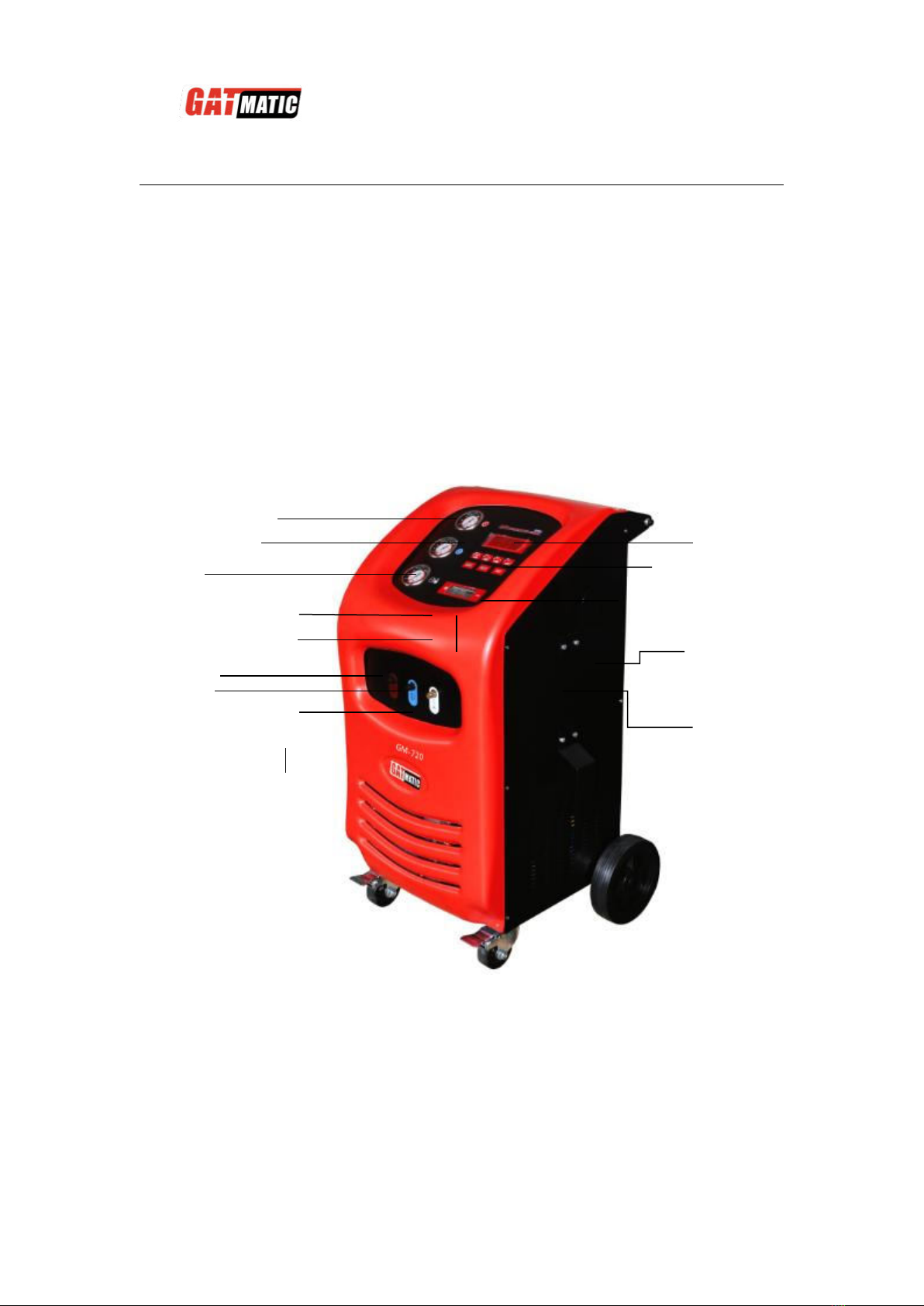
1) Parts descriptions
HP gauge
New oil bottle
Used oil bottle
Operation panel
Displayer
LP gauge
Switch for used oil discharge
Switch for new oil adding
HP port
Auxiliary Port
P gauge
Window
LP port
GM-720 A/C System Maintenance
Centre
4
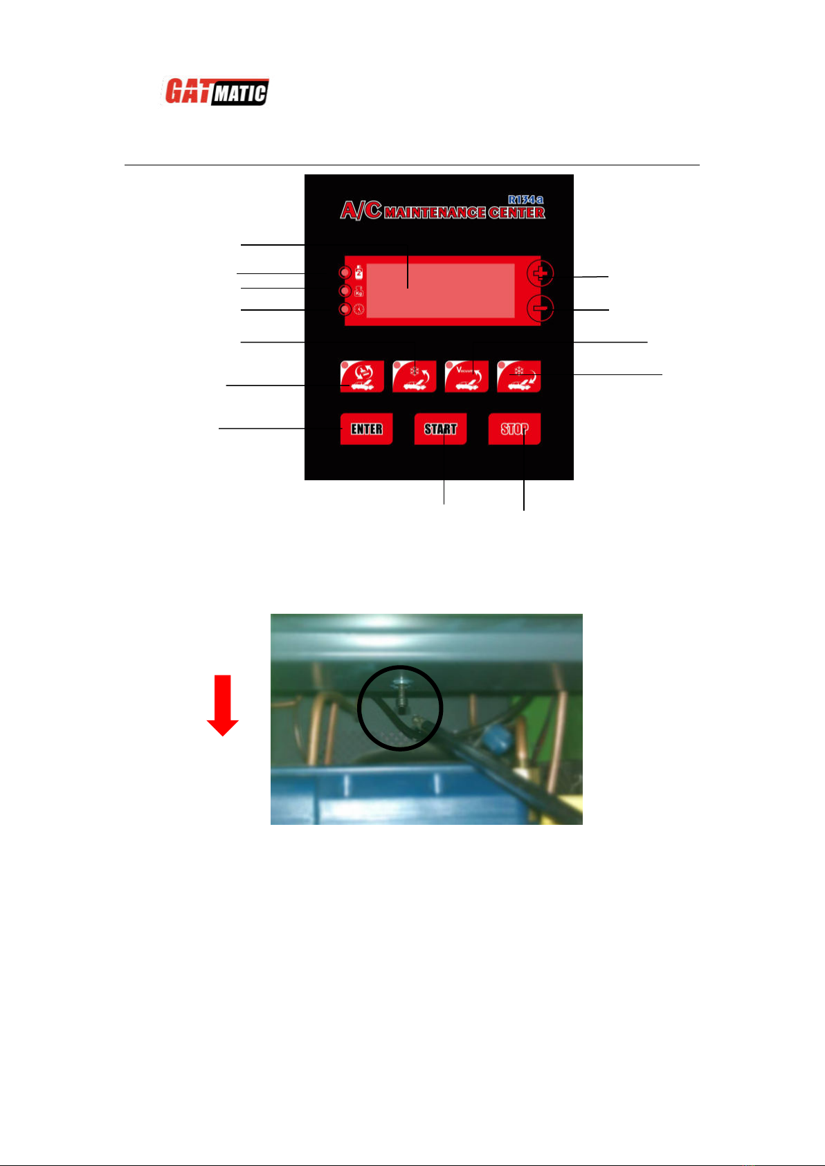
2) First use
A、Unscrew the electronic scale support screw before using the equipment.
B、Please supply about 4 kg refrigerants into the tank of equipment so that all
of the functions can be run normally.
C、Fix the refrigerant tank (Recharging tank) on the load cell.
From the back.
Unscrew the
support screw.
Parameter increase key
Parameter increase key
Enter key
Recovery key
Min indicator
Kg indicator
LED displayer
Vacuum key
Recharge key
Start key
Stop key
Recharging Tank indicator
Flush key

GM-720 A/C System Maintenance
Centre
5
1st Connect the hose port with needle to the Recharging Tank port of the machine and connect
another port of the hose to the refrigerant tank.
2nd Open the valve of the refrigerant tank and place it upside down on the load cell pan.
3rd Fix it with the accessories.
Note: If you need not using the auxiliary load cell, please fix it as the manufactory.
Warning: Non-pedal the auxiliary load cell!
D、Please read this user manual carefully before operating.
3) Recovery/Recycling
A、Pres key to select the Recovery/Recycling function:
B、The LED displays the weight of refrigerant in the cleaning tank (internal
tank).
C、Presses “START” key to run.
D
、
It will stop running and discharge the used oil automatically when the
recovery/recycling process finish.
Note: also be able to discharge the used oil by press the switch.
E、During the running process, if it displays a code as F00-, please refer to
the APPENDIX: ALARM CODE TABLE.
4) Preparations before Flushing
A、To check if there has enough refrigerant in the tank. The volume should be
4~6 kg.
B、Empty the used oil bottle.
C、Check the automotive A/C system. If there has any leakage, it must be
repaired firstly to avoid refrigerant leak during flushing process.
D、Check if the automotive air-conditioning can run normally.

GM-720 A/C System Maintenance
Centre
6
5) Flushing & Recovery
A、Before flushing the pipeline of automotive A/C system, please turn on A/C
system and run it for 5 to 10 minutes. And set it as the lowest temperature
and medium wind.
B、Turn off the automotive air conditioning.
Warning: do not start the air conditioning during the flushing process!
Otherwise, it easily causes damages to the air-conditioning and risk
of accident!
C、Press key to select the “Recovery/Flushing” function.
D、The LED displays the flushing time.
E、Set the flushing time by pressing “+” or “-” key and press “ENTER” key to
conform it. In order to achieve good flushing performance, the flushing
time should be more than 30 minutes. Normally, the good flushing time is
about 45 minutes for car.
Note: The flushing time does not include the time of recovery
process. Once the flushing is finished, the machine will run the
recovery function automatically.
F、Press “START” key to run the function.
G、Then the forward flushing, reverse flushing and pulse flushing will be
run.
H、If it displays code as F00- during the process, please refer to the
APPENDIX: ALARM CODE TABLE.
I、After flushing process finished, the recovery process run automatically.
J、When the whole process finished, it drain the used roil automatically.
Notice: it’s normal for that there have action sound of the solenoid
valve during the working process. Please do not stop it.
6) Vacuum
A、Press key to select the vacuum function.
B、The LED displays the vacuum time.

GM-720 A/C System Maintenance
Centre
7
C、Set the vacuum time by pressing "+" or "-" and press the "ENTER" key to
confirm it. It should be more than 15 minutes. Generally, it needs 15
minutes at least for the air conditioning only with front wind and 20 minutes
for with the front and rear wind.
D、Press “START” key to run it.
E、When the time is finished, it will stop automatically.
F、If it displays code as F00- during the process, please refer to the
APPENDIX: ALARM CODE TABLE.
7) New oil adding
A、Pour new oil into the new oil bottle.
Note: add new oil more 20ml than the used oil drained out to avoid
the air into the air conditioning system.
B、After vacuum, press the switch of the new oil bottle to control the new oil
filling.
Warning: please do not press the switch of the new oil bottle anytime
when the automotive air conditioning system in non-vacuum state,
otherwise it have the risk of explosive bottles!
8) Recharging
Note:
i. Here you can choice the cleaning tank (internal tank) or recharging
tank (external tank) to recharging the refrigerant into the A/C system.
ii. When the led as is on, it means that recharge the refrigerant from the

GM-720 A/C System Maintenance
Centre
8
recharging tank (external tank). Otherwise, from the cleaning tank (internal tank).
iii. It’s by cleaning tank (internal tank) to recharge as default. After fixed
the recharging tank (external tank), you can set to recharge refrigerant
from the recharging tank (external tank). The setting ways is referring
to the PARAMETER SETTING.
iv. When the refrigerant in the recharging tank (external tank) is not
enough, please exchange one tank of refrigerant. The exchanging
ways is referring to the RECHARGING TANK EXCHANGING.
Operations;
A、Press the key to select recharging function.
B、The led displays the amount of recharging.
C、Set filling amount by press “+” or “-” key, and then press “ENTER” key.
Note: set the filling amount according to automotive user manual.
The unit is kg.
D、Presses “START” key to run.
E、Stop automatically after recharging finished.
Note: In the filling process, if LED displays alternately the remaining
amount of filling and the letters "AC", it means that you need to turn
off the HP coupler and turn on the car air-conditioning to complete
the filling process. Later, you should supply new refrigerant into the
tank.
9) Maintenance
A、Calibration of load cell
When the load cell is not precise,it needs to be calibrated.
Calibrating procedure as below:
i. Prepare a 15 kg weight. And remove the refrigerant tank from scale pan
and keep the pan empty.
Note: do not disconnect the red and blue hose from the refrigerant
tank. It’s better put the refrigerant tank on a lower stage.
ii. Press and hold “STOP” key then power on the equipment. Press”+”or ”-”
to select the load cell of cleaning tank (internal tank, SEN1) or of the
recharging tank (external tank, SEN2). Press “ENTER” key to the
calibration process.
GM-720 A/C System Maintenance
Centre
9
iii. The LED displays “1” in flushing.
iv. Press "ENTER" key to do the empty plan calibration. Then the LED will
display “2” in flushing. Note: If LED shows “ERR1”,please refer to the
APPENDIX: ALARM CODE TABLE.
v. Put the 15 kg weight onto the scale pan and press “ENTER” key. Then
LED displays the weight value and adjusts the value to 15 by press “+” or
“-”key.
Note: if the weight is 20kg, the value must be set to 20.
vi. Press “ENTER” key to do the scale linear calibration. Then the LED
displays “END” to mean it’s successful for the calibration.
Note: if LED shows “ERR2”, please refer to the APPENDIX: ALARM
CODE TABLE.
vii. Then power off and replace and fasten the refrigerant tank onto the scale
pan.
B、Exchange dry filter
The dry filter must be exchange after used a period. The machine has set the
exchange time. When the dry filter reaches the life time, the LED will show
code “F004”. Now the dry filter must be exchanged.
i. Press and hold (VACUUM) key and power on the equipment.
ii. Press “START” key to do the first step automatically.
iii. Replace the used dry filter with a new one then press “ENTER” key.
iv. Input the dry filter ID. Please refer to the chapter PARAMETER
SETTING.
v. Power off and dry filter exchange procedure finish.
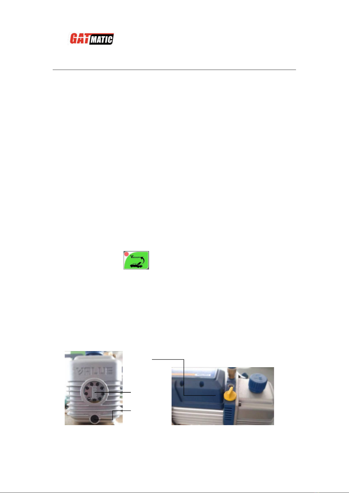
C、Change vacuum pump oil
i. When the pump oil became cream or the LED displays “F008”, the
vacuum pump oil must be changed.
Window
Drain port
Fill port

GM-720 A/C System Maintenance
Centre
10
ii. Step 1: unscrew the block of the drain port to drain entirely out the old oil.
Then re-back the block to the drain port.
iii. Step 2: unscrew the cap of the fill port and then fill the new oil slowly into
the vacuum pump until the oil level reach at the center site. Then
re-back the cap to the fill port.
Note: the new vacuum pump oil cannot be filled too much into the
vacuum pump otherwise it will spray out when working.
D、Recharging tank exchange
When there is no enough refrigerants in the recharging tank, it needs
to change a new tank of refrigerant in time so that the recharging
function can be run.
i. Press and hold the (flushing) key to power on.
ii. The LED displays the remained amount in the recharging tank.
iii. Press the “ENTER” key.
iv. When the LED displays the “CH”, please change a new tank of
refrigerant and fix it well.
v. Power off and exchange ok.
10) Parameter setting and inquiring
A、Parameter setting
i. Here can set the cleaning tank or recharging tank as the default
recharge tank.
ii. Press and hold the "START" key and power on the equipment to enter
the mode.
The LED displays the parameter code and you can change the code
by press "+” or “-" key.
iii. The LED displays “P3”.
iv. Press “ENTER” into setting mode. Press “+”or”-” to select the setting
value.
g: Set the unit is KG/G as default.
lb: Set the unit is LB as default.
v. Press “ENTER” to save.
vi. The LED displays “P4”.

GM-720 A/C System Maintenance
Centre
11
vii. Press “ENTER” into setting mode. Press “+”or”-” to select the setting
value.
C-1: Set the cleaning tank (internal tank) as default. This is also default
of nufactory.
C-2: Set the recharging tank (external tank) as default.
viii. Press “ENTER” to save.
ix. Power off.
B、Parameter inquiring
i. Press and hold (Recharging) key to enter parameter inquiring
mode.
ii. In this mode five parameters can be inquired.
The LED displays the parameter code and you can change the code by
press "+” or “-" key.
iii. Code “C”: total worked time of the compressor
When LED displays code "C", please press "OK" key to show the total
worked time.
iv. Code “P”: total worked time of the vacuum pump
When LED displays code "P", please press "OK" key to show the total
worked time.
v. Code “F”: volume of refrigerant dealt with by dry filter.
When LED displays code "P", please press "OK" key to show the total
worked time.
Reset this code by press together “Fill” and “Stop” keys and the ways of
dry-filter ID is as follows:
Dry filter ID is with 4 digits, and you need to set one by one.
When one digit is in flash, it means you can set it by press "+” or “-" key,
and press “OK” key to confirm it.
Set a same value according to the ID pasted on the dry-filter.
Only you set the correct 4 digits, the equipment can accept it
Note: The code used already will be not able to be accepted again.
vi. Code “CON”: total times of the equipment being operated.
vii. Code “SN”: the equipment serial number
GM-720 A/C System Maintenance
Centre
12
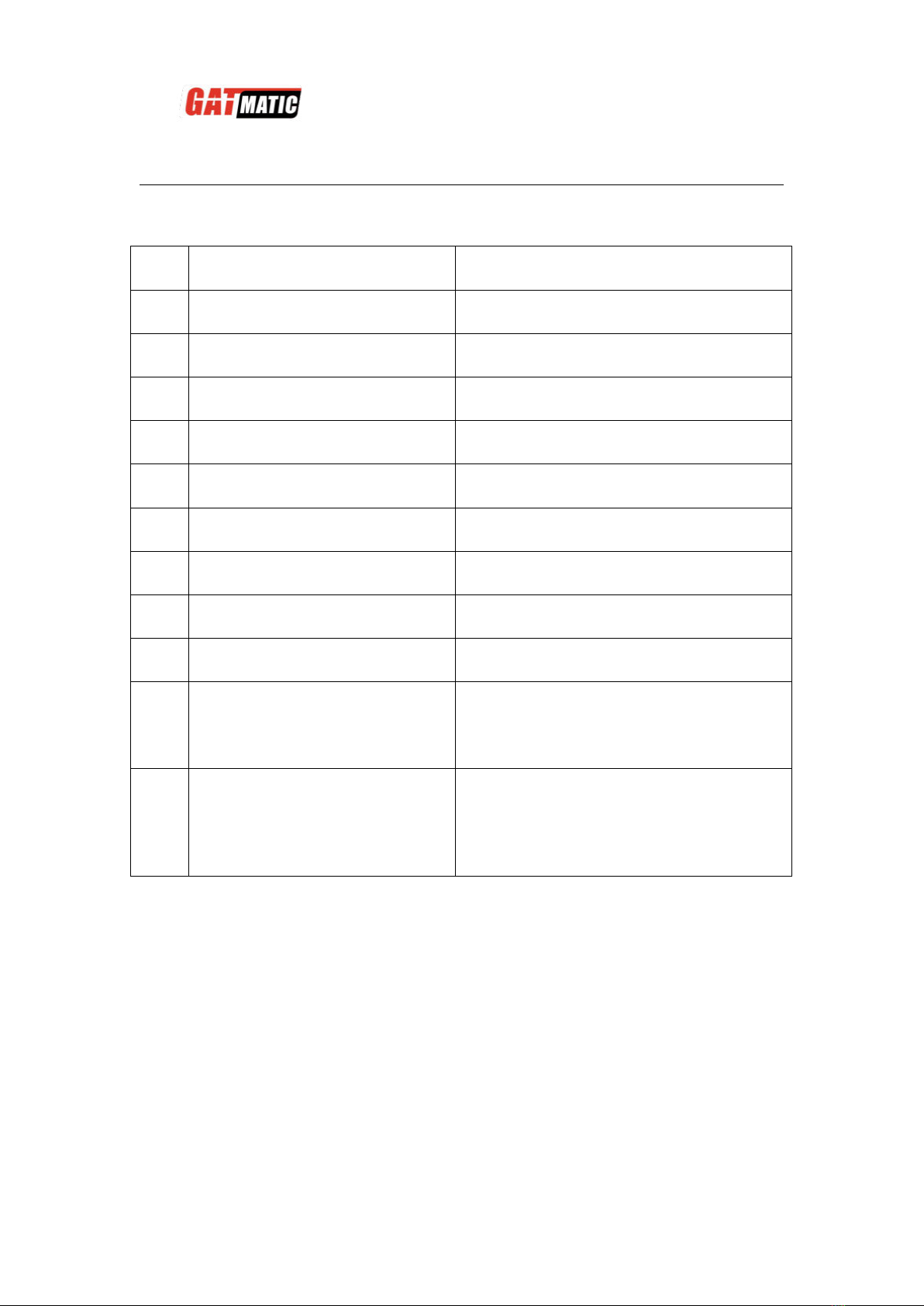
APPENDIX: ALARM CODE TABLE
Cod
e
Descriptions
Emergency Method
F00
1
No enough refrigerant in
cleaning tank
Supply refrigerant in time.
F00
2
Too much refrigerant in tank
Transfer some refrigerant to another
tank.
F00
3
High pressure
Stop use for a period.
F00
4
No refrigerant to recovery
Run next function.
F00
5
Cannot vacuum
Recovery first and then run vacuum.
F00
6
Exchange dry-filter
The dry-filter is life-end.
F00
7
Vacuum pump maintenance
Change the pump oil in time.
F00
9
No enough refrigerant in
recharging tank
Change a new tank of refrigerant.
F01
0
Prohibit changing the
recharging tank
Here has enough refrigerant in the
tank.
ERR
1
Load cell calibration error at
step 1
Check if the scale pan empty.
Check the connection of signal cable
being ok.
Check if the load cell is damaged.
ERR
2
Load cell calibration error at
step 2
Check if the weight has been put onto
the scale pan.
Check the connection of signal cable
being ok.
Check if the load cell is damaged.
Table of contents
Popular Welding System manuals by other brands

Comparc
Comparc DELTA MIG 455 owner's manual

Lincoln Electric
Lincoln Electric RANGER IM604-B Operator's manual

LENCO
LENCO L-6000 LENCOSPOT MARK III manual

ESAB
ESAB Caddy Tig 2200iw instruction manual

Chicago Electric
Chicago Electric 8878 Assembly and operation instructions

Riland
Riland CUT 100GT user manual


 user manual")


