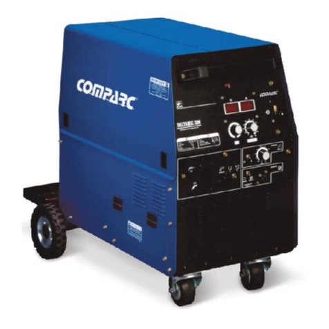
Comparc DELTA MIG 455 User manual

DELTAMIG 455
ARC WELDING POWER SOURCE
PM1327 REV. 0
E:21-01-2021
PROCESSES
DESCRIPTION
CONSTANTVOLTAGEOUTPUT(CV).
MIG(GMAW).
DIRECTCURRENTOUTPUT(DC).
THREEPHASES.
3
DC
CV
Phase
OWNER´SMANUAL
302-573
T M
OWNER´S MANUAL
GIVETHISMANUALTOTHEOPERATOR
VISIT OUR WEBSITE AT: www.comparcwelders.ca

TABLE OF CONTENTS
ARC WELDING SAFETY PRECAUTIONS ...............................................................................i
SECTION 1 -- SAFETY SIGNAL WORDS ................................................................................1
SECTION 2 -- SPECIFICATIONS .............................................................................................1
2 - 1. Volt-AmpereCurves..........................................................................................................................2
2 - 2. DutyCycle.......................................................................................................................................2
SECTION 3 -- INSTALLATION .................................................................................................3
3 - 1. Selectingalocationandmovingweldingpowersource ......................................................................3
3 - 2. Installingworkclamp ........................................................................................................................3
3 - 3 Installing support for MIG gun.......................................................................................................4
3 - 4. Selectingandpreparingweldoutputcables.......................................................................................5
3 - 5. 120V a.c. duplex receptacle ............................................................................................................5
3 - 6. Shieldedgasconnections.................................................................................................................6
3 - 7. Remote14andRemoteON-OFFreceptacles ...................................................................................6
3 - 8. Weldoutputterminals. .....................................................................................................................7
3 - 9. Inputpowerconnections... ................................................................................................................7
SECTION 4 -- OPERATION ......................................................................................................8
4 - 1. Locationof controlsinweldingpowersource .....................................................................................8
4 - 2. Powerswitch ...................................................................................................................................8
4 - 3. Output switch...................................................................................................................................8
4 - 4. V control switch. ..............................................................................................................................8
4 - 5. VoltageAdjustmentcontrol...............................................................................................................9
4 - 6. Digitalmeters...................................................................................................................................9
4 - 7. Safetyequipment. ............................................................................................................................9
4 - 8. OperationsequenceforGMAW,FCAW,SAW andCAC-A ..............................................................10
SECTION 5 -- MAINTENANCE AND TROUBLESHOOTING ................................................11
5 - 1. Routinemaintenance......................................................................................................................11
5 - 2. Overheating....................................................................................................................................11
5 - 3. Overloadprotection.........................................................................................................................12
5 - 4. Troubleshooting..............................................................................................................................12
SECTION 6 -- ELECTRICAL DIAGRAM.................................................................................14
SECTION 7 -- PARTS LIST ....................................................................................................15
7 - 1. Mainassembly...............................................................................................................................16
7 - 2. Rectifierassembly..........................................................................................................................17
WARRANTY

i
ARC WELDING SAFETY PRECAUTIONS
WARNING
PROTECTYOURSELFANDOTHERSFROMPOSSIBLESERIOUSINJURYORDEATH.KEEPCHILDRENAWAY.PACEMAKERWEARERSKEEP
AWAY UNTIL CONSULTING YOUR DOCTOR.
In welding, as in most jobs, exposure to certain hazards occurs. Welding is safe when precautions are taken. The safety information given
below is only a summary of the more complete safety information that will be found in the Safety Standards. Read and follow all Safety
Standards.
HAVE ALL INSTALLATION, OPERATION, MAINTENANCE, AND REPAIR WORK PERFORMED ONLY BY QUALIFIED PEOPLE.
ARC WELDING can be hazardous.
ELECTRIC SHOCK can kill.
Touching live electrical parts can cause fatal shocks
or severe burns. The electrode and work circuit is
electrically live whenever the output is on. The input
power circuit and machine internal circuits are also
live when power is on. In semiautomatic or automatic
wire welding, the wire, wire reel, drive roll housing,
and all metal parts touching the welding wire are electrically live.
Incorrectly installed or improperly grounded equiment is a hazard.
1.- Do not touch live electrical parts.
2.- Wear dry, hole-free insulating gloves and body protection.
3.- Insulate yourself from work and ground using dry insulating
mats or covers.
4.- Disconnect input power or stop engine before installing or
servicing this equipment.
5.- Properly install and ground this equipment according to this
Owner's Manual and national, state, and local codes.
6.- Turn off all equipment when not in use.
7.- Do not use worn, damaged, undersized, or poorly spliced cables.
8.- Do not wrap cables around your body.
9.- Ground the workpiece to a good electrical (earth) ground.
10.- Do not touch electrode while in contact with the work (ground)
circuit.
11.- Use only well-maintained equipment. Repair or replace damaged
parts at once.
12.- Wear a safety harness to prevent falling if working above floor
level.
13.- Keep all panels and cover securely in place.
ARC RAYS can burn eyes and skin;
NOISE can damage hearing.
Arc rays from the welding process produce intense
heat and strong ultraviolet rays that can burn eyes and
skin. Noise from some processes can damage hearing.
1.- Wear a welding helmet fitted with a proper shade
of filter (see ANSIZ49.1 listed in Safety Standards) to protect
your face and eyes when welding or watching.
2.- Wear approvedsafety glasses. Side shields recommended.
3.- Use protective screens or barriers to protect others from flash and
glade; warn others not to watch the arc.
4.- Wear protective clothing made from durable, flame- resistant mate
rial (wool and leather) and foot protection.
5.- Use approved ear plugs or ear muffs if noise level is high.
FUMES AND GASES can be hazardous
to your health.
Welding produces fumes and gases. Breathing these
fumes and gases can be hazardous to your health.
1.- Keep your head out of the fumes. Do not breath the fumes.
2.- If inside, ventilate the area and / or use exhaust at the arc to remove
welding fumes and gases.
3.- If ventilation is poor, use an approved air-supplied respirator.
4.- Read the Material Safety Data Sheets (MSDSs) and the
manufacturer´s instruction for metal, consumables, coatings, and
cleaners.
5.- Work in a confined space only if it is well ventilated, or while wearing
an air-supplied respirator. Shielding gases used for welding can
displace air causing injury or death. Be sure the breathing air is safe.
6.- Do not weld in locations near degreasing, cleaning, or spraying
operations. The heat and rays of the arc can react with vapors to
form highly toxic and irritating gases.
7.- Do not weld on coated metals, such as galvanized, lead, or cadmium
plated steel, unless the coating is removed from the weld area, the
area is well ventilated, and if necessary, while wearing an air-
supplied respirator. The coatings and any metals containing these
elements can give off toxic fumes if welded.
WELDING can cause fire or explosion.
Sparks and spatter fly off from the welding arc. The
flying sparks and hot metal, weld spatter, hot workpiece,
and hot equipment can cause fires and burns. Acciden-
tal contact of electrode or welding wire to metal objects
can cause sparks, overheating, or fire.
1.- Protect yourself and others from flying sparks and hot metal.
2.- Do not weld where flying sparks can strike flammable material.
3.- Remove all flammables within 35ft (10.7 m) of the welding arc. If
this is not possible, tightly cover them with approved covers.
4.- Be alert that welding sparks and hot materials from welding can
easily go through small cracks and openings to adjacent areas.
5.- Watch for fire, and keep a fire extinguisher nearby.
6.- Be aware that welding on a ceiling, floor, bulkhead, or partition can
cause fire on the hidden side.
7.- Do not weld on closed containers surch as tanks or drums.
8.- Connect work cable to the work as close to the welding areas as
practical to prevent welding current from traveling long, possibly
unknown paths and causing electric shock and fire hazards.
9.- Do not use welder to thaw frozen pipes.
10.- Remove stick electrode from holder or cut off welding wire at
contact tip when not in use.
11.- Wear oil-free protective garments such as leather gloves, heavy
shirt, cuffless trousers, high shoes, and a cap.

ii
FLYING SPARK AND HOT METAL can
cause injury
Chipping and grinding cause flying metal . As welds
cool, they can throw off slag.
CYLINDERS can explode if damaged.
Shieldinggas cylinders contain gas under high pressure.
If damaged, a cylinder can explode. Since gas cylinders
are normally part of the welding process, be sure to
treat them carefully.
1.- Protect compressed gas cylinders from excessive heat, mechanical
shocks, and arcs.
2.- Install and secure cylinders in an upright position by chaining them
to a stationary support or equipment cylinder rack to prevent falling
or tipping.
3.- Keep cylinders away from any welding or other electrical circuits.
4.- Never allow a welding electrode to touch any cylinder.
5.- Use only correct shielding gas cylinders, regulators, hoses, and
fittings designed for the specific application; maintain them and
associated parts in good condition.
6.- Turn face away from valve outlet when opening cylinder valve.
7.- Keep protective cap in place over valve except when cylinder is in
use or connected for use.
8.- Read and follow instructionson compressed gascylinders, associated
equipment, and CGA publication P-1 listed in Safety Standards.
ENGINES can be hazardous.
WARNING
ENGINE EXHAUST GASES can kill.
Engines produce harmful exhaust gases.
1.- Use equipment outside in open, well-ventilated
areas.
2.- If used in a closed area, vent engine exhaust outside and away from
any building air intakes.
ENGINE FUEL can cause fire or
explosion.
Engine fuel is highly flammable.
1.- Stop engine before checking or adding fuel.
2.- Do not add fuel while smoking or if unit is near any sparks or open
flames.
3.- Allow engine to cool before fueling. If possible, check and add fuel
to cold engine before beginning job.
4.- Do not overfill tank - allow room for fuel to expand.
5.- Do not spill fuel. If fuel is spilled, clean up before starting engine.
MOVING PARTS can cause injury.
Moving parts, such as fans, rotors, and belts can cut
fingers and hands and catch loose clothing.
1.- Keep all doors, panels, covers, and guards closed
and securely in place.
2.- Stop engine before installing or connecting unit.
3.- Have only qualified people remove guards or covers for maintenance
and troubleshooting as necessary.
4.- To prevent accidental stating during servicing, disconnect negative
(-) battery cable from battery.
5.- Keep hands, hair, loose clothing, and tools away from moving parts.
6.- Reinstall panels or guards and close doors when servicing is finished
and before starting engine.
SPARKS can cause BATTERY GASES
TO EXPLODE; BATTERY ACID can
burn eyes and skin.
Batteries contain acid and generate explosive gases.
1.- Always wear a face shield when working on a
battery.
2.- Stop engine before disconnecting or connecting battery cables.
3.- Do not allow tools to cause sparks when working on a battery.
4.- Do not use welder to charge batteries or jump start vehicles.
5.- Observe correct polarity (+ and -) on batteries.
STEAM AND PRESSURIZED HOT
COOLANT can burn face, eyes, and
skin.
The coolant in the radiator can be very hot and under
pressure.
1.- Do not remove radiator cap when engine is hot. Allow engine to cool.
2.- Wear gloves and put a rag over cap area when removing cap.
3.- Allow pressure to escape before completely removing cap.
1.- Wear approved face shield or safety goggles. Side shields
recommended.
2.- Wear proper body protection to protect skin.

1
* Including running gear and lifting eye.
SECTION 2 - SPECIFICATIONS
SECTION 1 - SAFETY SIGNAL WORDS
MODEL OUTPUT
TYPE
RATED
OUTPUT AT
100% D.C. OVERALL
DIMENSIONS
AMPERES INPUT AT RATED LOAD
OUTPUT, 60 Hz THREE-PHASE
450 A
38 VDC
WEIGHT:NET
(SHIP)
230 V 460 V kW kVA
MAX. OPEN
CIRCUIT
VOLTAGE
VOLTAGE
RANGE
450 AMP DC / CV 10-38 VDC 70 A 35 A 22,2 27,8 228 Kgs.
(236 Kgs.)
DEPTH:
1232 mm
WIDTH:
571 mm
*HEIGHT:
838 mm
48 VDC
WARNING
CAUTION
IMPORTANT: Statements identify special instructionsnecessaryforthemostefficientoperationof thisequipment.
WARNING statements identify procedures or practices which must be followed to
avoid seriuos personal injuryor loss of life.
CAUTIONstatementsidentifyproceduresorpracticeswhichmustbefollowedtoavoid
minor personal injury or damage to this equipment.
Thefollowingsafetyalertsymbolandsignalwordsareusedthroughoutthismanualtocallattentiontoandidentifydifferent
levelsof hazardandspecialinstructions.
575 V
28 A

% DUTY CYCLE
Duty cycle 100% at 450 Amp.
2-1 VOLT-AMPERE CURVES.
2
Definition:
Duty Cycle is percentage of 10 minutes that unit can
weld at rated load without overheating.
Thevolt-amperecurvesshowtheminimumandmaximumvoltageandamperageoutputcapabilitiesoftheweldingpower
source.Curvesofothersettingsfall betweenthecurvesshown.
2-2 DUTY CYCLE.
EXCEEDINGDUTYCYCLECANDAMAGEUNITORGUNTORCHANDVOIDWARRANTY.
CAUTION
100 % Duty cycle.
Continuouswelding.
WELDAMPERES
10
0
MINUTES
100
0
20
500
300
700
900
200
600
400
800
10
30
50
40
60
70
80
MAX.
MIN.
GMAW
FCAW
CD AMPERES
DC VOLTS
450 A
30
200
300
600
400
800
1000
50
60
70
80
100 C.T.
90

SECTION 3 - INSTALLATION
3.1 SELECTING A LOCATION AND MOVING WELDING POWER SOURCE.
Figure3-1.Connectionfor GMAW &FCAW process.
3
CAUTION SEE SAFETY SIGNAL AT THE BEGINING THIS MANUAL
Figure 3-2 Locationandmovingwelding powersource.
2
Rear
Left
Front Right
Up
1
Figure 3-3 Workclamp.
3-2 INSTALLING WORK CLAMP.
Power Source
14 Pins Wire
Feeder
GMAW Gun
Work Piece
Power Source
14 Pins Wire
Feeder
GMAW Gun
Work Piece
-Solid Wire Weld Connection (GMAW);
ReversePolarity(ElectrodePositive.)
-Fluxcoredweldconnection(FCAW);Straight
Polarity(ElectrodeNegative.)
1.- 10 in (254 mm) open space
on right side and left of unit
for good airflow.
2.- Lifting eye. Use only lifting
eye for lift unit.
9.5, 11.1 mm(3/8, 7/16")
1.-WorkCablefromUnit.
2.- Contact Piece.
3.-Screw.
4.-WorkClamp.
5.-Washer.
Tools Needed
3
1
5
2
4

4
3-3 INSTALLING SUPPORT FOR MIG GUN.
1.- Remove two screws (1/4" x 1/2" ) in cover (2) and side deckl (3) as shown in figure.
2.- Place the support on the cover (1) and beside deck (2) as shown in figure.
3.- Ensure the support (1) with screws (1/4" x 1") (4).
Tools needed:
- 3/8"
To place the support for MIG gun on welding power source, follow instructions bellow.
2
3
4
1
4

3-4 SELECTING AND PREPARING WELD OUTPUT CABLES.
1.- Weld circuit cable.
To select weld cable size, proceed as follows:
a)- Calculate total cable length in weld circuit
b)- Determine maximum welding current and
duty cycle.
c)- Use table 3-1 to select proper cable size.
2.- Terminal lug. Use lugs of proper amperage
capacity and hole size for connecting to weld
output terminals.
3.- Work clamp. Instal on work cable.
Figure 3-4 Weldoutputcables
5
60 -100%
Duty cycle
100
150
200
250
300
350
400
500
600
700
800
4
3
3
2
1
1/0
1/0
2/0
3/0
4/0
4/0
4
3
2
1
1/0
2/0
2/0
3/0
4/0
2-2/0
2-2/0
4
2
1
1/0
2/0
3/0
3/0
4/0
2-2/0
2-3/0
2-3/0
3
1
1/0
2/0
3/0
4/0
4/0
2-2/0
2-3/0
2-4/0
2-4/0
2
1/0
2/0
3/0
4/0
2-2/0
2-2/0
2-3/0
2-4/0
3-3/0
3-4/0
1
2/0
3/0
4/0
2-2/0
2-3/0
2-3/0
2-4/0
3-3/0
3-4/0
3-4/0
1/0
3/0
4/0
2-2/0
2-3/0
2-3/0
2-4/0
3-3/0
3-4/0
3-4/0
4-4/0
1/0
3/0
4/0
2-2/0
2-3/0
2-4/0
2-4/0
3-3/0
3-4/0
4-4/0
4-4/0
10 - 60%
Duty cycle 10 - 100% Duty cycle.
Welding
amperes
150 ft
(45 m) 200 ft
(60 m) 250 ft
(75 m) 300 ft
(90 m) 350 ft
(105 m) 400 ft
(120 m)
100 ft (30 m) or less
* Weld cable size (AWG) is based on either a 4 volts or less drop or a current density of not more than 300 circular mils per ampere. Use
weld cable with insulation rating equal to or greater than the open-circuit voltage of the unit.
Table 3-1 Weld cable size.*
Total cable (Copper) length in weld circuit not exceeding
1.-Duplex receptacle (RC2), this receptacle provide up
to (120V @10 A) a.c., the power is shared between
Remote-14 (RC8), CB1 protects to RC2 and RC8 from
overload.
Figure3-5.120Va.c.duplexreceptacle.
3-5 120 V a.c. DUPLEX RECEPTACLE.
1
2
3
10 ft (3m)
10 ft (3m)
For Example, Total cable length in weld circuit = 20 ft (6 m)
1
To wire feeder.

OUTPUT
(CONTACTOR)
INFORMATION
Socket
REMOTE-14
A
B
I
J
G
K
C
E
D
F
H
24 V a.c. Protected by CB2 (10 Amperes).
Contact closure to "A" completes 24 V a.c. contactor control circuit.
120 V a.c. Protected by CB1(10 Amperes).
Contact closure to "I" completes 120 V a.c. contactor control circuit.
Circuit common for 24 and 120 V a.c. circuits.
Chassis common.
Command reference 10 V d.c.
0 to +10 V d.c. input command signal from remote control.
Remote control circuit common.
Current feedback 0-10 V d.c. 1 Volt per100 weld output Amperes.
Voltage feedback 0-10 V d.c. 1 Volt per 10 weld output Volts
NOTE: Remaining sockets are not used
TABLE 3-2. REMOTE-14 RECEPTACLE INFORMATION.
Figure3-6 Shieldedgasconnection.
WARNING SEE SAFETY SIGNALS AT THE BEGINING THIS MANUAL
6
3-6 SHIELDED GAS CONNECTIONS.
Figure3-7.Remote-14andRemoteON-OFF
3-7 REMOTE 14 AND REMOTE ON-OFF RECEPTACLES
1- Remote-14 receptacle RC8 (See table 3-2)
2-
Keyway
3- Plug connector 14
4- Collar
5- Remote ON-OFF receptacle (See table 3-3)
To connect this receptacle, align keyway, insert plug and
tighten threated collar.
Turn off power before connecting remote 14 or
remote ON-OFF receptacles
1
2
3
4
5
6
G N D
REMOTEOUTPUT
CONTROL
A/ V
INFORMATION
SOCKETS
REMOTEON-OFF
TABLE 3-3. REMOTE ON-OFF RECEPTACLE INFORMATION.
24V a.c. with 'POWER'' switch in ''OFF'' position.
Contact closure to "2" completes 24 V a.c. remote power circuit.
ON-OFF
RMT 2
3
Be sure gas cylinder is held to running gear, wall, or other stationary support
so cylinder can not fall and break off valve.
1.-CAP.
2.-CYLINDERVALVE.
Remove cap, stand to side of valve, and open valve slightly. Gas flow blows
dust and dirt from valve. Close valve.
3.-CYLINDER.
4.-REGULATOR/FLOWMETER.
5.-GASHOSECONNECTION.
6.-FLOWADJUST.
Typical flow rate is 20 cfh ( Cubic Feet per Hour).
28.5, 15.8mm (1-1/8",5/8")
Toolsneeded:
NOTE: Remaining sockets are not used
1
342
3
4
2
1
5

7
3-8 WELD OUTPUT TERMINALS
1- Access door.
2- Positive Terminal (+), High Inductance.
Usethis terminal for MIG STAINLESS STEEL WELDING.
3- Positive Terminal (+), Low Inductance.
Use this terminal for most wire feeding GMAW process (FCAW and SAW).
However, since usage and application vary.
4- Negative Terminal (-).
Common for welding circuit.
Welding polarity.
CDEP welding in d.c. whith positive electrode (Microwire in Feeder).
CDEN welding in d.c. with negative electrode (Microwire in Feeder).
Turn off power before connecting to weld output terminals.
Close access door before weld process begining.
Figure3-8.WeldOutputTerminals.
19 mm (3/4")
Tabla 3-3. Cable size and recommended fuse.
Figure3-9.Inputpowerconnections.
3-9 INPUT POWER CONNECTIONS.
32
41
Tools Needed:
ELECTRICK SHOCK can kill.
WARNING
ELECTRICK SHOCK can kill.
WARNING
Input voltage:
Rated input current:
Fuse or circuit breaker recommended:
AWG Power cable size :
AWG Ground cable size:
230V ~
52 A.
75 A.
6
8
460V ~
26 A.
50 A.
10
10
575V ~
21 A.
40 A.
10
10
Jumperlinksallowsoperation to
diferentinputvoltages.
Openreardoorandmovejumper
linkstomatchinputvoltageasshownlabel
toadecuatevoltage.
1-CONNECTIONDIAGRAM.
2-PRIMARYPANEL.
3-POWERSWITCH.Connect theinput
to the switch, using cable size and fuse
capacity according nameplate.
1
2
3
Toolsneeded
9.5mm (3/8") 11.1mm (7/16")
2 0 VOLTS
3
460 VOLTS
575
VOLTS
L1
L1
L1
1 2 3 4 5 6 1 2 3 4 5 6 1 2 3 4 5 6
1 2 3 4 5 6 1 2 3 4 5 6 1 2 3 4 5 6
1 2 3 4 5 6 1 2 3 4 5 6 1 2 3 4 5 6
L2
L2
L2
L3
L3
L3
1
2
3
4
5
6
1
2
3
4
5
6
1
2
3
4
5
6

4-1 LOCATION OF CONTROLS IN WELDING POWER SOURCE.
8
CAUTION
SECTION - 4 OPERATION
SEE SAFETY SIGNALS AT THE
BEGINING THIS MANUAL
Figure 4-1 Controls
1- ''POWER'' Switch.
ON - OFF
2- ''V CONTROL'' Switch.
PANEL - REMOTE.
3- ''OUTPUT'' Switch.
ON-REMOTE.
4-''VOLTAGE ADJUSTMENT'' Control.
Turn clockwise to increase voltage.
5- Digital voltmeter.
6- Digital ammeter.
Figure 4-2. " POWER ''
* POWER switch
Turn on and turn off the power source.
ON
OFF
POWER
ON
REMOTE
OUTPUT
* OUTPUT switch
PANEL position for front panel control of output, weld output terminals are
energized.
REMOTE position for remote control of output, needed connect remote device
in Remote - 14 receptacle.
Figure 4-3. ''OUTPUT''
H
E
C
H
O
E
N
M
E
X
I
C
O
1
2
3
5
4
6
4-2 ''POWER'' SWITCH
4-3 ''OUTPUT'' SWITCH
* Voltage CONTROL switch
PANEL position for front voltage control.
REMOTE position for remote voltage control, needed connect
remote device in Remote-14 receptacle.
Figure 4-4. ''VCONTROL''
4-4 ''V CONTROL'' SWITCH
PANEL
REMOTE
V
CONTROL

Figure 4-6. Digital voltmeter and ammeter.
DIGITALVOLTMETERANDAMMETER.
Whith "contactor off". Voltmeter display PRESET voltage and ammeter is turn off.
Whith "contactor on". Voltmeter and ammeter display actual output voltage and
amperage, ammeter remains off if current is zero amperes.
While welding, the meters measure and display the output arc voltage and amperage.
once extinguished the arc, the digital meters retained the arc values approx 4 sec.,
subsequently shown PRESET value.
9
VOLTAGE ADJUSTMENT
* VOLTAGE ADJUSTMENT control.
To increase arc voltage output, turn control clockwise.
Voltmeter value changes as control is turned. While welding this
control can be adjusted.
Figure 4-5. ''VOLTAGE ADJUST''
4-5 ''VOLTAGE ADJUSTMENT'' CONTROL
4-6 DIGITAL METERS.
Figure 4-7 Safetyequipment.
4-7 SAFETY EQUIPMENT.
1.- Insulator gloves.
2.- Safety Glases with side shields.
3.- Welding Helmet.
4.- Ear Muffs.
1 3 2 4
Wear dry insulating gloves, safety glasses with side shields
and a welding helmet with correct filter shade (See ANSI
Z49.1).
Wear aproved ear muffs of ear plugs if noise exposure exceeds

10
Breathing welding fumes can be hazardous to your health.
1.- Cylinder.
2.- Cylinder valve.
3.- Gun torch trigger.
Before welding open cylinder valve, to activate the trigger
the arc welding is started.
Finishing welding shut the cylinder valve.
3
2
1
Figure 4-8. Gas supply.
CAUTION
4-8 OPERATION SEQUENCE FOR GMAW, FCAW, SAW AND CAC-A.
Install and
connect the
equipment
Turn On Wire feeder
and Power Source
Put On
safety
equipment
Install and
prepare Flux
system
Install and
prepare
wire feeder
Set Control Turn On Flux
system Beging welding
Figure 4-11 Submerged arc process (SAW)
Readjsut
controls and
begin welding
Open
gas
valve
Turn On Wire
feeder and Power
Source
Put On
safety
equipment
Install and
prepare
wire feeder
Install and
connect the
equipment
Figure 4-10 Flux cored arc welding process (FCAW).
Figure 4-9 Solid wire process (GMAW).
Readjsut
controls and
begin welding
Put On
safety
equipment
Install and
prepare
wire feeder
Install and
connect the
equipment
Turn On Wire
feeder and Power
Source
Set Controls
Put On
safety
equipment.
Select
coat
electrode
Connect
compreser air
system
Inssert electrode into
torch Supply
compresed air Turn On Power
Source Start cutting or
gouging
Install and
connect the
equipment
Figure 4-12 Air cutting and gouging process (CAC-A).

11
SECTION - 5
MAINTENANCE &TROUBLESHOOTING
5-1 ROUTINE MAINTENANCE
WARNING SEE SAFETY SIGNAL AT THE BEGINING THIS MANUAL
5-2 OVERHEATING.
START
WELDING
PROCESS
Figure 5-1 Overheatprotection.
1- This unit is designed to initially operate with cooling system.
2- While unit works, the cooling system maintains a safe temperature so as not to damage internal components
3- If the cooling system was not enough and the temperature rises to unsafe values, the unit interrupt output and
deploys in the voltmeter and ammeter the message ''ESP ErE'', the cooling system will continue to operate; when the
machine has a temperature to operate safely restart output and the message ''ESP ErE'' disappears.
4- On the one overheating or failure in the cooling system, the machine will shut down and internally is disconnected from
the line alimenteción..
CONTINUE
WELDING
PROCESS
1234
TIME
Above normal equipment use: Check all labels ( see 6 month entry ), repair any damaged
insulation or replace holder or work cable, clean internal parts ( see 6 month entry ), clean and
tighten connections at holder cable and work clamp.
Everymonth
Every3months
Every6months
MAINTENANCE
Replace Unreadable Labels, Tape Or Replace Cracket Cables, Clean And Tighten Weld
Terminals, Replace Cracket Parts.
Blow Out Or Vacuum inside,During Heavy Service Clean Monthly.

12
Check fuses and replace if necessary, or reset circuit breakers
Check for proper input power connections
Place power switch in ON position
Place line disconnect device in ON position.
Noweldoutput,unitcompletely
inoperative.
No weld output, wire does not
feedbutmotorfanrun.
Be sure plug trigger conector in receptacle and work clamp in work piece.
REMEDY
PROBLEM
Figure 5-2 Overloadprotection.
Disconnet unit before inspection.
1.- CIRCUIT BREAKER CB1(10 AMP).
Protect the 120 V c.a. cicuit for overload.
''Presss button to reset breaker''
2.-CIRCUIT BREAKER CB2 (10AMP).
Protect the 24 V c.a. cicuit for overload.
''Presss button to reset breaker''
2
5-3 OVERLOAD PROTECTION.
3
1
TABLA 5-1. TROUBLE WITH WELDING
5-4 TROUBLESHOOTING.
3.- Fuse f1 (5 AMP)
Protect at control transformer from overload, if F1
open, fan motor and output unit stops.
.
''Replace if F1 is openfuse''.
Close and secure access door before restart unit.
Consult your dealer or Service Center to review the connections and when
necessary the electronic board.

Check torch according gun torch owner´s manual. Replace damage parts.
Readjust drive rolls pressure.
Check and replace contact tip if necessary.
Check and remove any obstruction in wire feeder mechanism.
Be sure plug trigger connector is in receptacle for gun trigger.
Consult your dealer or Service Center to review the connections and when
necessary the electronic board in welding power source.
Consult your dealer or Service Center to review, mechanism, connections and
when necessary the electronic board in wire feeder.
TABLE 5-2. TROUBLE WITH MIG GUN AND WIRE FEEDER.
Wire feed but stops during
weldingprocess
REMEDYTROUBLE
REMEDY
PROBLEM
Be sure jumper links is in position according voltage available at site..
Adjust the control voltage according application.
Lowweldoutputcurrent.
No weld output, wire feed is
working. Consult your dealer or Service Center to review the connections and when
necessary the electronic board.
Connect the work clamp for assure electric contact
13

14
SECTION - 6 ELECTRICAL DIAGRAM
Figure 6-1 Electrical Diagram
D
E
L
T
A
M
I
G
4
5
5
1
1
1
1
1
1
1
1
1
2
2
2
2
2
2
2
2
2
3
3
3
3
3
3
575 VO
L
T
S
A
C
460 VO
L
T
S
A
C
2
3
0
V
O
L
T
S
A
C
3
3
3
4
4
4
4
4
4
4
4
4
5
5
5
5
5
5
5
5
5
6
6
6
6
6
6
6
6
6
1
1
1
2
2
2
3
3
3
4
4
4
5
5
5
6
6
6
2
3
0
V
4
6
0
V
2
3
0
V
1
PPP
23456
5
7
5
V
F4
F5
F6
F7
F8
F
2
F
3

15
PC0145
PC0990
PM0347
PS0881
PS1027
PT3620
PT3621
PT1794
PT1826
PA0827
MA01108
MM04206
MR01495
MR01520
MR06632
PS1611
PT2654
PA0829
MB04284
MC10192
MI00110
MM04109
MP03137
MP08417
MR00521
MR09784
MI01196
PP3157
PP4578
PT0923
PT0924
PT1875
PS1761
PA1216
MC10687
MS03942
PB1449
PE0649
PR1044
PS0878
PS1128
PT1185
PT3611
PT3615
MF02316
PP3784
MR09754
PB1967
2
1
1
1
1
1
1
1
2
1
1
1
1
1
2
1
1
1
1
1
1
1
1
1
1
1
2
1
1
1
2
1
1
1
1
1
1
1
1
1
2
1
1
1
1
1
2
1
SECTION - 7 PARTS LIST
7-1 MAIN ASSEMBLY
Item
No.
1
2
3
4
5
6
7
8
9
11
12
13
14
15
16
17
18
19
20
21
22
23
24
25
26
27
Part No. D e s c r i p t i o n Quantity
PC1
FM
R1
R3,R4
CB1,CB2
S3
R5
RC2
CR1
S1, S2
W1
HD1
Z1
T1
F1
I.D.
Safetychain
Cover,top
Handlebars
Supportforcylinder
SopportforMIGgun.
Panel,leftside
Panel,right side
ControlPCB
DigitalmeterPCB
Panel,rearASSEMBLY
Blade,16"VA-407
Motorpower1/6PSC481646-0883
Resistor ww 20 ohm 10% 300W
Support,rubberNo.4
Resistor ww 200 ohm 5% 25W
Fan,motorsupport
Panel,rear
Panel,frontASSEMBLY
Bushing
Circuit breaker10amps.
Switch, SPST
Opticalfilter(redcolor)
Potentiometer1k2w
Knob, pointer1 5/8"
Receptacle120Va.c
RelayDPDT. 24Va.c.
Switch SPDT
Door,frontterminaloutput
Dataplate,hinged
Terminal,poweroutputblack
Terminal,poweroutputred
Panel, front withPCB box
Supportassembly,forrectifier
ChassisASSEMBY
Contactor
Transducer,halldevice1000amphta-1000-s/sp16
Bafle,andTransducersupport
Stabilizerassembly
Wheelrear,assembly
Bracket, contactor
Support,powermaintransformer
Frame,lifting
Transformer,mainassembly
Panel,primaryconnectionsandfuseholder
Fuse5 amp
Rectifier, main (SCR) (figure 7-2)
Wheel front,rotating 6"
Capacitor,bank
List 7-1 Main assembly parts.

16
Figure 7-1 Main assembly.
6
3
2
18
17
5
16
1
4
11
23
7
19
20
15
14
12
9
10
25
8
26
24
27
Table of contents
Other Comparc Welding System manuals
Popular Welding System manuals by other brands

Miller
Miller SuitCase X-TREME 8VS CE owner's manual

Clarke
Clarke Fluxcore/MIG 135sg WE6441 operating manual

Leister
Leister FUSION 3 operating instructions

Leister
Leister SEAMTEK 36 operating manual

Lincoln Electric
Lincoln Electric PRO-CUTTM 25 IM665 Operator's manual

WIA
WIA Weldmatic 190 Operator's manual