Gator G4 User manual

Our policy is one of continue research and development in the quest to improve our products. We therefore reserve the rights to amend information provided in this
document, without notice.
For sales or technical support please contact Irri-Gator Products (Pty) Ltd at: Tel: +27 21 9827561, Fax: +27 21 9814473, E-mail: i[email protected]
P. O. Box 889, Brackenfell, 7561, Western Cape Province, South Africa
Installation guide for the Gator G4
Radio Receiver Module
MOUNTING THE RADIO RECEIVER MODULE
Always mount the radio receiver module in clear open air.
Mount the module in the horizontal plain with the window facing downwards as shown in the Figure 1
below.
Figure 1
Mount the receiver module onto a stainless steel receiver bracket using the modules mounting slot as
shown in figure 2 below. Insert an M5 machined screw through the hole provided in the top of the
modules mounting bracket and lock this in place with a machine nut to secure the module.
Figure 2
Mount the receiver module along with its bracket on a solid pole or other suitable solid structure as high
is as practically possible. Refer to Figure 3 below as example.
Figure 3

Our policy is one of continue research and development in the quest to improve our products. We therefore reserve the rights to amend information provided in this
document, without notice.
For sales or technical support please contact Irri-Gator Products (Pty) Ltd at: Tel: +27 21 9827561, Fax: +27 21 9814473, E-mail: i[email protected]
P. O. Box 889, Brackenfell, 7561, Western Cape Province, South Africa
Installation guide for the Gator G4
Radio Receiver Module
When mounting the receiver module and bracket to the outside of a building, make sure to locate the
module on the building wall that is facing the transmitter’s antennae. In built up areas this may not be
possible but test this location to make sure you obtain acceptable signal quality before mounting the unit.
It is generally best practice to locate the switching devices such as solenoids and relays as close as
possible to the receiver module. This will be explained in more detail under the “CONNECTING THE
OUTPUT DEVICES TO THE RADIO RECEIVER MODULE” section.
NOTE!!!
Do not mount the receiver module on any structure that is subjected to vibration. E.g. Avoid mounting the
receiver module on a valve riser assembly as the riser assembly is subjected to vibration while water
flow takes place.
Avoid mounting the radio receiver module in a metal or concrete enclosure or structure. Even a metal
cage will negatively influence radio signal. It is acceptable to mount the receiver module within a plastic
enclosure as shown in Figure 4
Figure 4
Avoid mounting the radio receiver in any location where corrosive gases are present.
Do not mount the receiver module underground.
Do not mount the receiver module in any location that can become flooded.
Avoid mounting the receiver module where it will be subjected to water jet/s. E.g. Do not mount the unit
directly next to a sprinkler where the jet of water being emitted by the sprinkler hits the receiver module.
Avoid locating the receiver module in dense vegetation and foliage.
Make certain acceptable radio reception is achievable when locating a receiver module in the vicinity of
high voltage power lines.
CONNECTING THE OUTPUT DEVICES TO THE RADIO RECEIVER MODULE
The G4 Gator radio receiver module is available in two output connection formats.
The output plug format as shown in Figure 5 below
Figure 5

Our policy is one of continue research and development in the quest to improve our products. We therefore reserve the rights to amend information provided in this
document, without notice.
For sales or technical support please contact Irri-Gator Products (Pty) Ltd at: Tel: +27 21 9827561, Fax: +27 21 9814473, E-mail: i[email protected]
P. O. Box 889, Brackenfell, 7561, Western Cape Province, South Africa
Installation guide for the Gator G4
Radio Receiver Module
The output wire loom format as shown in Figure 6 below
Figure 6
It is advisable to locate the output devices to be switched by the radio receiver module, such as solenoids and
relays, as close to the receiver module as is practically possible. These output devices are activated with a short
DC pulse signal and long cable/wire run lengths between the output device and the radio receiver module can
be problematic (can cause intermittent operation).
We do not suggest that you exceed 5m in total cable/wire length between the radio receiver module and the
output device to be controlled. Use a wire size of 1.5mm² if you intend to locate the output device/s away from
the receiver module up to 5m away.
The Gator G4.0 radio receiver module uses a two wire 12VDC pulse signal of 60mSec in length. Compatible
output devices should be selected to meet this specification and tested properly for reliable use with the radio
receiver module. Consult with Irri-Gator Products for a list of approved devices.
Connecting the output devices to the G4.0 receiver module equipped with the plug connection format
This version of the G4 radio receiver module is equipped with a 6 terminal pins and a plug (black and
blue) as shown in Figure 7 below.
Figure 7
Looking from the rear (the mounting slot end) of the radio receiver module the terminals are as follows –
Terminal 1 –Common (Black)
Terminal 2 –Common (Black)
Terminal 3 –Output #1 (Blue)
Terminal 4 –Output #2 (Blue)
Terminal 5 –Output #3 (Blue)
Terminal 6 –Output #4 (Blue)
Figure 8 below shows two solenoid valves that have wire to the radio receiver modules terminal plug. The
green wire (plus) from solenoid valve #1 is wired to the first blue terminal (terminal 3 being the closest
blue terminal to the black terminals). The green wire (plus) from solenoid valve #2 is wired to the second
blue terminal (terminal 4). The black wires (minus) are wired to the black terminals in no specific order.

Our policy is one of continue research and development in the quest to improve our products. We therefore reserve the rights to amend information provided in this
document, without notice.
For sales or technical support please contact Irri-Gator Products (Pty) Ltd at: Tel: +27 21 9827561, Fax: +27 21 9814473, E-mail: i[email protected]
P. O. Box 889, Brackenfell, 7561, Western Cape Province, South Africa
Installation guide for the Gator G4
Radio Receiver Module
The two black terminals are the same.
Figure 8
Wiring the 3 and 4 output would entail connecting the green wire for the 3rd output device to terminal 5
(blue block) and the green wire for the 4th output device to terminal 6 (blue block). The black wires from
both output devices would connect to either terminal 1 or 2 (the black blocks).
Once the wiring of the output devices to the terminal connector has been completed the connector can be
plugged into the pins on the base of the radio receiver module as shown in Figure 9 below.
Figure 9
We recommend to remove this terminal connector from the radio receiver module once a year and to
clean the pins on the module as well as to thoroughly clean the plug. Apply a good quality anti rust
inhibitor spray such as silicone before reattaching the connector to the receiver module.

Our policy is one of continue research and development in the quest to improve our products. We therefore reserve the rights to amend information provided in this
document, without notice.
For sales or technical support please contact Irri-Gator Products (Pty) Ltd at: Tel: +27 21 9827561, Fax: +27 21 9814473, E-mail: i[email protected]
P. O. Box 889, Brackenfell, 7561, Western Cape Province, South Africa
Installation guide for the Gator G4
Radio Receiver Module
Connecting the output devices to the G4.0 receiver module equipped with the output wire loom format
This version of the G4 radio receiver module is equipped with a short piece of 6 core cable which is
attached on one end to the radio receiver module using a waterproof joint. The other end of the cable has
6 soldered tinted wire ends exposed with ends, ready for attaching to the output devices as shown in
Figure 9 below.
Figure 10
The 6 wires are allocated as follows -
Red –Common
Black - Common Reserved (Reserved for future use. Remove the temporary heat shrink if you will use this wire)
Yellow –Output #1
Blue –Output #2 (Reserved for future use. Remove the temporary heat shrink if you will use this wire)
White –Output #3 (Reserved for future use. Remove the temporary heat shrink if you will use this wire)
Green –Output #4 (Reserved for future use. Remove the temporary heat shrink if you will use this wire)
It is recommended to make a waterproof connection between these wires and the output device wires.
This can be achieved by terminating the connections in an additional enclosure or using a waterproof gel
type connector such as the sample shown in Figure 11 below.
Figure 11
PROGRAMMING THE RADIO RECEIVER MODULE
The G4 Gator radio receiver module is programmed using a Hand Held Programmer. Information relating
to this process is available in a separate document titled “G4 RX Module Programming Guide”. If you do
not have this document on record, feel free to contact Irri-Gator Products and we will forward a copy.

Our policy is one of continue research and development in the quest to improve our products. We therefore reserve the rights to amend information provided in this
document, without notice.
For sales or technical support please contact Irri-Gator Products (Pty) Ltd at: Tel: +27 21 9827561, Fax: +27 21 9814473, E-mail: i[email protected]
P. O. Box 889, Brackenfell, 7561, Western Cape Province, South Africa
Installation guide for the Gator G4
Radio Receiver Module
APPLYING POWER TO THE RADIO RECEIVER MODULE
The Gator G4.0 radio receiver module makes use of a 3.6VDC 19A/Hr Lithium-thionyl Chloride battery to
power the unit. This battery pack is equipped with a wire loom and a connector socket as shown in Figure
12 below
Figure 12
The G4.0 radio receiver module has two wire looms located in the battery compartment of the module as
shown in Figure 13 below. The Green, White and Purple wire loom is used for programming the receiver
module using the hand held programmer. The red and black wire look fitted with the connector plug is the
module power point that is to be connected to the battery when power is to be applied.
Figure 13
Open the battery housing on the receiver module by removing the rubber plug from the receiver
modules battery compartment (Do not use any sharp instruments to achieve this).
Referring to Figure 13 above, extract the battery, battery cable and the programming cable out of the
receiver modules battery compartment.
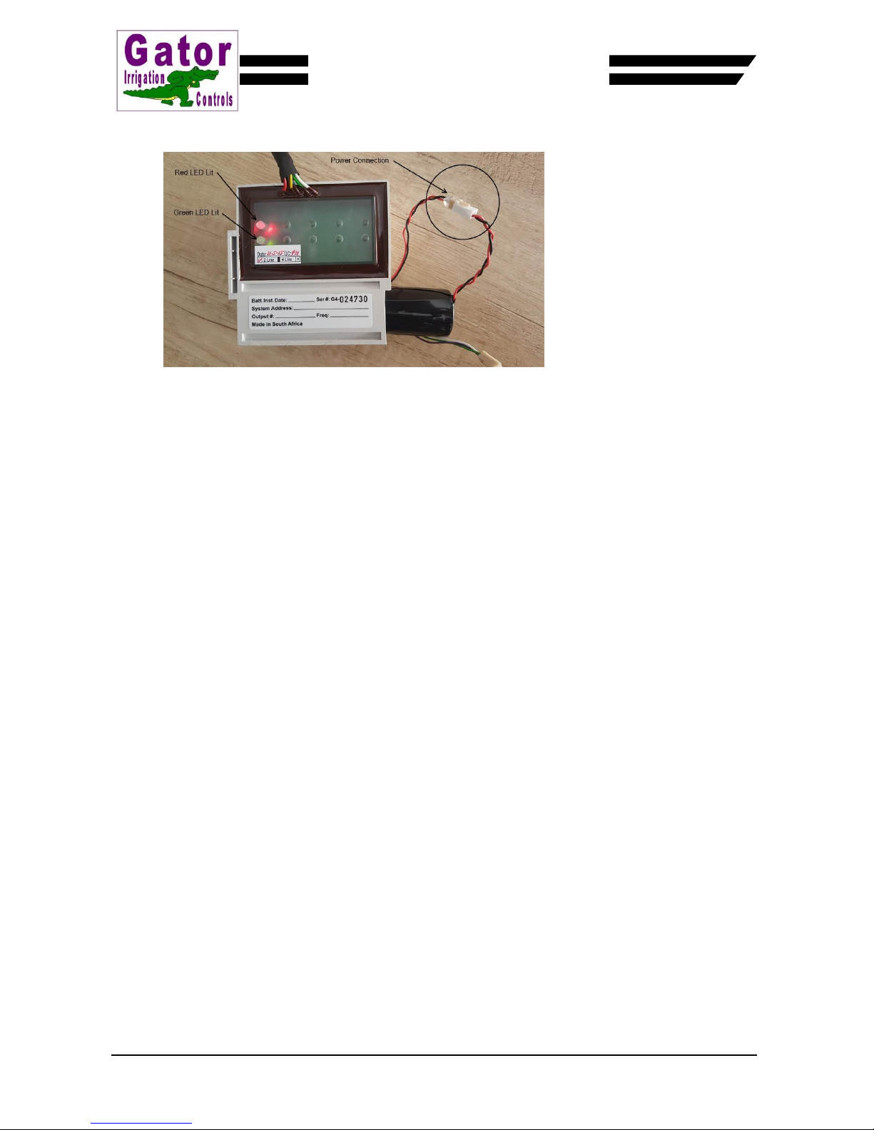
Referring to Figure 14 below, plug the battery connector socket into the radio receiver modules power
connector plug (red and black wires).
Figure 14
You will observe that both the Red and the Green LED’s will illuminate together.

Our policy is one of continue research and development in the quest to improve our products. We therefore reserve the rights to amend information provided in this
document, without notice.
For sales or technical support please contact Irri-Gator Products (Pty) Ltd at: Tel: +27 21 9827561, Fax: +27 21 9814473, E-mail: i[email protected]
P. O. Box 889, Brackenfell, 7561, Western Cape Province, South Africa
Installation guide for the Gator G4
Radio Receiver Module
When the green LED extinguishes, an audible click will be heard from each of the solenoids connected
to the receiver module as a reset of each output device takes place. Other output devices do not
necessarily omit this audible clicking noise during the resetting procedure.
The Red LED will remain on for approximately 2 to 3 minutes after the battery was reconnected.
While the Red LED is illuminated and should a radio signal applicable to this receiver module (ID being
the same as the transmitted signal), be received by the unit, the green LED will flash briefly.
If data that pertains to one or more of the outputs has been received by the module, the output/s will be
activated or deactivated dependant on the status requested. At this time the green LED will also flash
briefly.
The Red LED will extinguish after 2 to 3 minutes to conserve power consumption. No LED’s can be
observed after this time.
Gently insert the battery along with the wires and connectors into the radio receiver modules battery
compartment. Firmly secure the rubber plug into the receiver modules battery compartment making
sure that the “D” is facing upwards and that the plug is fully inserted.
RESETTING THE RADIO RECEIVER MODULE
From time to time the system operator may wish to clean a solenoid valve/s or check on the condition of the
radio receiver modules battery or simply reset the radio receiver module processor. The best way to achieve
this is to reset the radio receiver module which is explained as follows –
Open the battery housing on the receiver module by removing the rubber plug from the receiver
modules battery compartment (Do not use any sharp instruments to achieve this).
Gently extract the battery, battery cable and the programming cable out of the receiver modules battery
compartment.
Disconnect the battery connectors socket from the receiver modules connector plug.
To perform a reset on the receiver module power needs to be fully removed. When the battery is
unplugged it could take up to 60 minutes for power in the module to dissipate. To hasten this process it
is possible to use a hand held programmer to reset the module however If you do not have a Hand Held
Programmer available you will need to perform a manual reset.
Bridge out the black wires terminal pin with the green wires terminal socket for about 2 seconds on the
receiver module as shown in Figure 15 below.
Figure 15
Our policy is one of continue research and development in the quest to improve our products. We therefore reserve the rights to amend information provided in this
document, without notice.
For sales or technical support please contact Irri-Gator Products (Pty) Ltd at: Tel: +27 21 9827561, Fax: +27 21 9814473, E-mail: i[email protected]
P. O. Box 889, Brackenfell, 7561, Western Cape Province, South Africa
Installation guide for the Gator G4
Radio Receiver Module
Referring to Figure 16 below, plug the battery connector socket into the radio receiver modules power
connector plug (red and black wires).
Figure 16
You will observe that both the Red and the Green LED’s will illuminate together.
When the green LED extinguishes, an audible click will be heard from each of the solenoids connected
to the receiver module as a reset of each output device takes place. Other output devices do not
necessarily omit this audible clicking noise during the resetting procedure.
The Red LED will remain on for approximately 5 minutes after the battery was reconnected.
While the Red LED is illuminated and should a radio signal applicable to this receiver module (ID being
the same as the transmitted signal), be received by the unit, the green LED will flash briefly.
If data that pertains to one or more of the outputs has been received by the module, the output/s will be
activated or deactivated dependant on the status requested. At this time the green LED will also flash
briefly.
The Red LED will extinguish after 2 to 3 minutes to conserve power consumption. No LED’s can be
observed after this time.
Gently insert the battery along with the wires and connectors into the radio receiver modules battery
compartment. Firmly secure the rubber plug into the receiver modules battery compartment making
sure that the “D” is facing upwards and that the plug is fully inserted.

Our policy is one of continue research and development in the quest to improve our products. We therefore reserve the rights to amend information provided in this
document, without notice.
For sales or technical support please contact Irri-Gator Products (Pty) Ltd at: Tel: +27 21 9827561, Fax: +27 21 9814473, E-mail: i[email protected]
P. O. Box 889, Brackenfell, 7561, Western Cape Province, South Africa
Installation guide for the Gator G4
Radio Receiver Module
INSTALLING THE PROTECTION HOOD
The radio receiver protection hood provides additional protection to the radio receiver module against various
environmental conditions (bird and other animal defecation, temperature, moisture, sunlight, etc.). Follow the
procedures as described below to fit the hood to an existing receiver modules installation.
Remove the M5 securing screw from the hole in the top of the receiver modules stainless steel
mounting bracket.
Install the protection hood by inserting the blade of the mounting bracket through the slot in the hood as
shown in Figure 17 below.
Figure 17
Push the hood down making sure that the locating lips are behind the stainless steel bracket as shown
in Figure 18 below. Do not force the hood down and make sure a gap is retained between the receiver
module and the hood.
Figure 18

Our policy is one of continue research and development in the quest to improve our products. We therefore reserve the rights to amend information provided in this
document, without notice.
For sales or technical support please contact Irri-Gator Products (Pty) Ltd at: Tel: +27 21 9827561, Fax: +27 21 9814473, E-mail: i[email protected]
P. O. Box 889, Brackenfell, 7561, Western Cape Province, South Africa
Installation guide for the Gator G4
Radio Receiver Module
GENERAL NOTES
Do not drop the receiver module as this could lead to permanent damage to sensitive electronic
components.
Keep the receiver module in its original packaging until the unit is on site and ready to be installed. This
provides optimum protection to the equipment during the transport process.
Avoid exposing the module to high vibration and or shock as this can lead to permanent damage to the
equipment.
Do not attempt to modify the equipment or the electronics as this will deem the warranty void and may
lead to permanent damage of the equipment.
*********************************


