Gavita Pro 1700 LED EU 240 User manual
1
Pro line
1 Introduction
Thank you for purchasing the Gavita Pro 1700 LED EU. This manual describes the mounting and installing of the product and
also describes how to use the product. Mounting and installing of the Gavita Pro 1700 LED EU may only be executed by certified
service personnel. Please read and understand this manual completely before using the product. Only use the product as
specified in this manual.
1.1 Used Symbols
Warning! A warning indicates severe damage to the user and/or product may occur when a procedure is not carried
out as described.
Caution! A caution sign indicates problems may occur if a procedure is not carried out as described. It may also serve
as a reminder to the user.
Note: A note gives additional information, e.g. for a procedure.
This symbol is an internationally recognized symbol used to designate recyclable materials.
With this symbol Gavita declares that this product complies with European requirements.
The symbol on the material, accessories or packaging indicates that this product may not be discarded as household
waste. By properly disposing the equipment, you will be helping to prevent possible risks to the environment and public
health, which might otherwise be caused by improper handling of the discarded equipment. Recycling of materials
contributes to the conservation of natural resources. Therefore, please do not dispose of old electronics and electrical
appliances via household waste.
This symbol indicates the minimum distance (B) between the LED fixture (A) and the lit surface.
2 Product description
The Gavita Pro 1700 LED EU is an electronic horticultural LED fixture. It drives eight LED rails. The Gavita Pro 1700 LED EU
is intended to be used in greenhouses or in climate rooms. In this manual, the Gavita Pro 1700 LED EU will be referred to as:
“the LED fixture”.
3 Product information and specifications
3.1 General product information
Product name Gavita Pro 1700eLED
Manufacturer Hawthorne Gardening Company
Version EU UK CH ZA AUS
Part number HGC906059 HGC906060 HGC906065 HGC906067 HGC906068
EAN Code 8718403056556 8718403056563 8718403056570 8718403056600 8718403056587
Plug type EU plug 230 V UK plug 240 V CH plug 230 V ZA plug 240 V AUS/NZS Plug 240V
Gavita Pro 1700 LED EU
A B

2
3.2 Technical specifications
Product name Gavita Pro 1700 LED EU
Input voltage +/- 10% 240 VAC
Input wattage +/- 7% 645 W
Input current at 100% 2.7 A
Power factor 0.96
Product weight 12.9 kg
Dimensions (LxWxH) 112 x 111 x 8.5 cm
Operating temperature 0-40° C
Frequency 50 Hz
Certification standards CE LVD, CE EMC
Power inlet Wieland RST 16i5 connector
External dim: E-series adapter
Environment IP56
3.3 Compatible products and accessories
Product Product name Gavita part number
Controllers Gavita Master Controller EL1 EU/UK HGC990786
Gavita Master Controller EL2 EU/UK HGC990789
E-series Adapter Gavita e-series adapter EU 240 HGC906154
Power cords
Gavita Power cord ESA UK 2.5 meter PC6852003
Gavita Power cord ESA EU 2.5 meter PC6852002
Gavita Power cord ESA CH 2.5 meter PC6852001
Gavita Power cord ESA AUS 2.5 meter PC6852005
Interconnect cables
Gavita Interconnect cable ESA RJ45-RJ45 10 ft/3.0m HGC906711
Gavita Controller cable ESA RJ45-RJ9 25 ft/7.5m HGC906717
Gavita Controller cable ESA RJ45-RJ9 10 ft/3.0m HGC906716
Gavita 3 way splitter ESA 1f to 2f RJ45 HGC906721
Sun Grips Sun Grip Original Light Hanger 1/8 in black AC906721
Crimp tool Crimp tool HGC906720
3.4 Environment
The product is intended to be used in greenhouses and climate rooms. The product can be used in wet environments.
The product may not be used outdoors. The Gavita Pro 1700 LED EU functions optimal when the max ambient temperature is
between 20~40° C.
3.5 Legal
CE LVD approval according to: EN61347-1:2015, EN61347-2-11:2014+A1:2017
CE EMC approval according to: IEC61347-1:2015, IEC61347-1:2015/AMD1:2017, IEC61347-2-11:2001, IEC61347-2-11:2001/
AMD:2017

3
4 Safety recommendations and warnings
Warning! Carefully read the warnings below before using or working with the product!
• Always adhere to the local rules and regulations when installing or using the LED fixture.
• Do not open or disassemble the LED fixture, it contains no serviceable parts inside. Opening or modifying the LED fixture
can be dangerous and will void the warranty.
• This product may cause interference to radio equipment and should not be installed near maritime safety communications
equipment or other critical navigation or communication equipment operating between 0.45 - 30 MHz.
• Do not use the LED fixture when either the LED fixture or its power cord are damaged. Replace the power cord only with
original certified cords.
• Modifications to the cords can lead to unwanted electromagnetic effects, which makes the product not comply with legal
requirements.
• Do not expose the LED fixture to:
- (ambient) temperatures outside the specified range;
- dust and contamination;
- direct sunlight during use or HID light that could heat up the ballast.
• Always disconnect the LED fixture from mains before performing any maintenance.
• Always allow for a cool down period of at least 30 minutes before touching the LED rails. Touching the LED rails when the
fixture is lit or immediately afterwards can result in severe burns!
• Do not use the LED fixture near flammable, explosive or reactive substances. Do not use sulfur vaporizers or water misters.
• The installation and use of the LED fixture is the responsibility of the end user. Incorrect use or installation can lead to
failure and damage to the LED fixture. Damage to the LED fixture and electronic circuitry as a result of incorrect installation
and use revokes the warranty.
5 Contents (1)
A. Gavita Pro 1700 LED EU 240
1. LED drivers
2. LED rails
3. Mounting points
B. Sun Grip light hangers (4x)
C. Wieland RST 16i5 female connector
D. Interconnect cable ESA RJ45 - RJ45 3.0 m.
E. Controller cable ESA RJ45 - RJ9 3.0 m.
A
A2
B
A1
C
A3
1.
CH plug 230 V ZA plug 240 VEU plug 230 V UK plug 240 VAUS plug 240 V

4
6 Installation
Warning! Mounting and installing of the LED fixture may only be executed by certified service personnel, in accordance with
the applicable local laws and regulations.
Warning! The installer is responsible for correct and safe installation.
Warning! Ensure the local cabling can support the voltage and current requirements of the LED fixture.
Warning! Avoid coiled cords and keep mains leads separated. This prevents electromagnetic interference.
Warning! Do not connect or disconnect the LED fixture under load.
6.1 Installation preparations
Warning! Mount the system to something that can hold the weight of the LED fixture.
• Switch off mains power.
• Install the Sun Grip light hangers (B).
• Distribute the fixture weight evenly so fixture hangs level (fig. 3). Sun Grip light hangers allow the LED fixture to easily move
upwards and downwards (fig. 4) according to your crop height. (fig. 5)
• Make sure power cords:
1) Are not concealed or extended through a wall, floor, ceiling, or other parts of the building structures
2) Are not located above a suspended ceiling or dropped ceiling.
3) Are not permanently affixed to the building structure.
4) Are routed so that they are not subject to strain and are protected from physical damage.
5) Are visible over their entire length.
6) Are used within their rated ampacity as determined for the maximum temperature of the installed environment
specified in the instructions.
6.2 Installing the LED fixture
• Hang the LED fixture to the mounting system.
To install other LED fixtures, repeat the steps at paragraph 7.1 and 7.2.
640W
0.6 m
750W
0.75 m
2. 3. 4.
645W
5
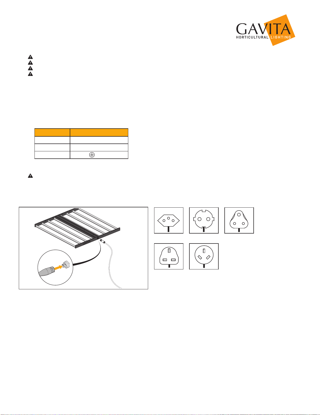
6.3 Connecting the LED fixture to the mains
Warning! Make sure mains power is switched off.
Warning! Ensure the cord is not coiled and does not touch any hot surfaces.
Warning! Connect the cables according to local rules, safety regulations and electrical code.
Warning! Ensure external switching gear can cope with the inrush current of the LED fixture (see paragraph 3.2). Always
use a double pole contactor suitable for switching a capacitive load. Never use household timers to switch the LED fixture!
• If you use the LED fixture stand alone, connect the Wieland RST 16i5 female connector on the power cable to the Wieland
RST16i5 male connector on the LED fixture (fig. 13).
• If you use the LED fixture with a Master Controller, connect the Wieland RST16i5 female connector on an E-series adapter
(not included) to the Wieland RST16i5 male connector on the LED fixture (fig. 14).
• Connect the power cable to the mains.
Cable description Gavita Pro 1700 LED EU:
Wire 230-240 V
Brown Phase (L)
Blue Neutral (N)
Yellow/Green Ground ( )
• Switch on mains power.
Warning! Do not connect or disconnect the power cable to the LED fixture while under load.
5.
CH plug 230 V EU plug 230 V
UK plug 240 V AUS plug 240 V
ZA plug 240 V
6
7 Connecting multiple LED fixtures to a controller
Warning! Mounting and installing of the E-series adapter(s) may only be executed by certified service personnel, in
accordance with the applicable local laws and regulations.
Warning! The installer is responsible for correct and safe installation.
Warning! Ensure the local cabling can support the voltage and current requirements of the LED fixture and E-series adapter.
Warning! Avoid coiled cords and keep mains leads separated. This prevents electromagnetic interference.
Warning! Do not connect or disconnect the LED fixture under load.
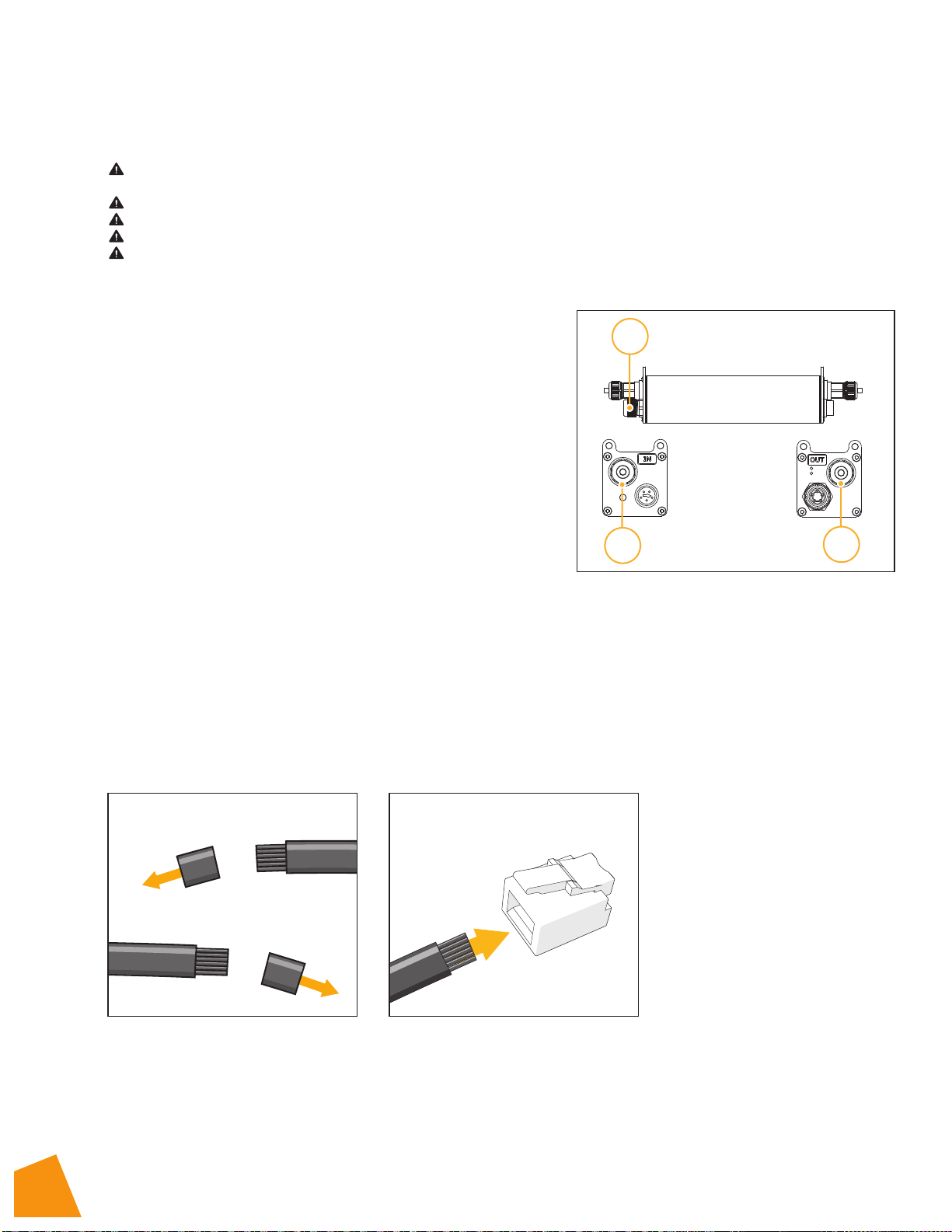
7.1 Contents E-series adapter (fig. 8)
*Not included, sold separately.
A. Wieland RST 16i5 male connector
B. Gavita 2xRJ connector
1. RJ IN
2. RJ OUT
7.2 Contents of the repeater bus connection kit
*Not included, sold separately.
The E-series adapter interconnect kit contains the following items:
C. 80ft interconnect cable
D. RJ45 + 3x RJ14 terminal connectors (3x)
OPTIONAL:
• Interconnect cable, 3 way splitter
• Interconnect cable, crimper
• Crimp tool
7.3 Preparation for use with a controller
Using a daisy chain setup, a maximum of 100 E-series adapters can be connected to one controller. Up to 500 E-series
adapters per daisy chain can be connected when using splitters. See section 7.4 and 7.5 of this manual and the manual of the
controller.
• Take the unstripped interconnect cable.
• Cut the cable to the desired length and strip both ends using a crimp tool (fig. 7).
• Insert the cable end in the RJ connectors (fig. 8) and use a crimp tool to finish the assembly.
B1 B2
A
6.
7. 8.

7
7.4 Connecting up to 100 E-series adapters
• Remove the dummy plug from the input port on the first LED adapter (fig. 9).
Note: Keep the dummy in a safe place! The dummy is necessary to operate the
E-series adapter in standalone mode.
• Use the black controller cable (RJ45 - RJ9) to connect the controller input port on
the first E-series adapter (fig. 10A).
• Remove the dummy from the input port on the second E-series adapter.
• Use interconnect cable (RJ45 - RJ45) to connect the output port of the first E-series
adapter to the input port of the second E-series adapter (fig. 10B).
• Repeat these steps to connect up to 100 E-series adapters (fig. 10C).
Warning! Ensure the power cord and the controller cables do not touch any of the
LED rails.
9.
10.
1
2
Max 100
A
B
C
8
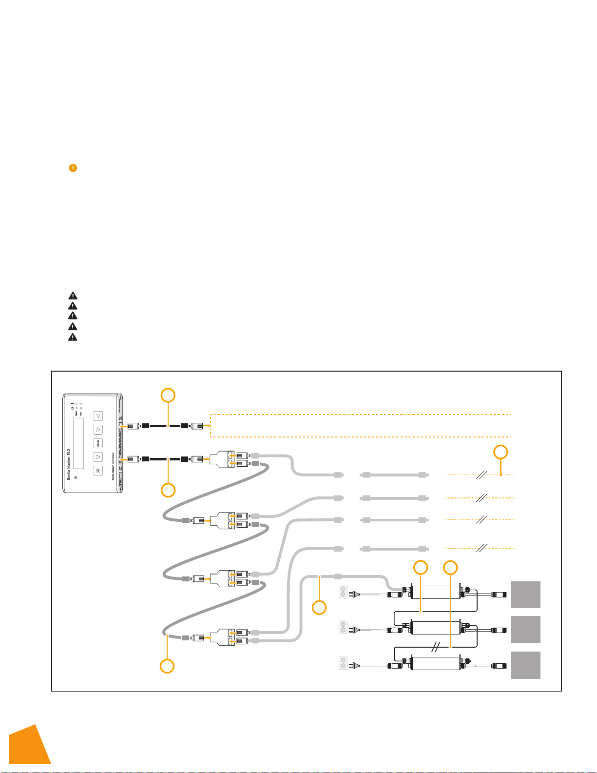
7.5 Connecting up to 500 or 1000 E-series adapters
Using a setup with daisy chained splitters, up to 500 E-series adapters on EL1 and 1000 E-series adapters on EL2 (over two
channels) can be connected as shown in fig. 12.
• Use the controller cable (RJ45 - RJ9) to connect the primary channel of the controller to the input port of the first splitter
(fig. 12A).
• Remove the dummy from the input port of the E-series adapter (fig. 10).
Note: Keep the dummy in a safe place! The dummy is necessary to operate the E-series adapter in standalone mode.
• Use a RJ45 - RJ45 modular jack interconnect cable (item C) to connect the output port of the splitter to the input port of
the first E-series adapter (fig. 12C).
• Use a RJ45 - RJ45 modular jack interconnect cable (item C) to connect the output port of the first E-series adapter to the
input port of the second (fig. 12D).
• Repeat these steps to connect up to 100 E-series adapters per splitter output port (fig. 12E). Up to 500 E-series adapters can
be connected to the primary channel.
• Use RJ45 - RJ45 modular jack interconnect cables (item C) to connect the outport of a splitter to the input port of the next
splitter (fig. 12F).
• Use the secondary channel (fig. 12G) to connect another 500 E-series adapters in the same way the E-series adapters are
connected to the primary channel.
Warning! Ensure the power cord and the controller cables do not touch the E-series adapters.
Warning! Distribute number of E-series adapters evenly over daisy chains.
Warning! Ensure the repeater bus connections are integrated in a correctly set up installation for best results.
Warning! Boosters should never be used to expand.
Warning! The maximum cable length per splitter is 250m (100 interconnect cables).
1
2
100
101 102 200
201 202 300
401 402 500
F
301 302 400
501 - 1000
B
A
G
1700e
LED
FIXTURE
1700e
LED
FIXTURE
1700e
LED
FIXTURE
DE
C
11.

9
8 Precautions when using the LED fixture and E-series adapter
Warning! Always wait 20 - 30 minutes for the LED fixture to cool down!
9 Inspection, maintenance and repair
Warning! Disconnect the LED fixture from mains before performing any maintenance or repairs.
Warning! Do not connect or disconnect the LED fixture under load.
Warning! Do not open or disassemble the LED fixture or E-series adapter, they contain no serviceable parts inside. Opening
the LED fixture or E-series adapter can be dangerous and will void the warranty.
Warning! Always allow for a cool down period of at least 30 minutes before touching the LED fixture.
Caution! Do not clean the LED fixture with detergents, abrasives or other aggressive substances.
•Regularly check the LED fixture for dust or dirt buildup. Clean if necessary. Contamination may cause overheating and
decreased performance. Clean the outside of the LED fixture using a dry or damp cloth.
•Regularly check the cables of the LED fixture to ensure it is undamaged.
9.1 How to disconnect the Wieland RST16i5 plug
Warning! Do not connect or disconnect the Wieland RST16i5 plug under load.
•Switch off mains power.
•Turn the ring on the Wieland RST16i5 female connector counterclockwise and pull the
Wieland RST16i5 female connection from the LED fixture (fig. 15).
10 Storage and disposal
•Store the LED fixture in a dry and clean environment, with an ambient temperature of
-20~85° C.
•The product must not be discarded as unsorted municipal waste, but must be collected
separately for the purpose of treatment, recovery and environmentally sound disposal.
11 Warranty service
Gavita International b.v. warrants the mechanical and electronic components of their product to be free of defects in material
and workmanship if used under normal operating conditions for a period of five (5) years from the original date of purchase. If
the product shows any defects within this period and that defect is not due to user error or improper use Gavita International
b.v. shall, at its discretion, either replace or repair the product using suitable new or reconditioned products or parts. In case
Gavita International b.v. decides to replace the entire product, this limited warranty shall apply to the replacement product for
the remaining initial warranty period, i.e. five (5) years from the date of purchase of the original product. For service return the
Gavita Pro 1700eLED fixture to your shop with the original sales receipt. PLEASE NOTE: greater than 15% of the diodes must be
non-functional before the unit can be considered defective.
1
2
12.

121100
Manual: Gavita Pro 1700eLED EU
Changes reserved - Version 20/18
Not for sale or use in the Netherlands
GAVITA International bv
Oosteinderweg 127
1432 AH Aalsmeer
The Netherlands
Tel: +31(0)297-380 450
Fax: +31(0)297-380 451
W: www.gavita.com
Table of contents
Other Gavita Outdoor Light manuals

Popular Outdoor Light manuals by other brands


LUMI TEAM
LUMI TEAM CITY STREET LED Mounting instructions

Hella marine
Hella marine 2LT 959 941-011 instruction sheet

FLOS
FLOS NOCTAMBULE F manual

Patriot Lighting
Patriot Lighting Waterdrop-24FT-SL installation manual

Inspire
Inspire MEADOW E27 Assembly, Use, Maintenance Manual

Daro
Daro PASO TRI F1 instruction manual