Gbord EBC-310L Series User manual
EBC-310L Series
Rugged Type Embedded BOX PC
User’s Manual
1st Ed –13 February 2018
Overview
Icon Descriptions
The icons are used in the manual to serve as an
Indication of interest topics or important messages.
Below is a description of these icons:
NOTE: This check mark indicates that there
is a note of interest and is something that
you should pay special attention to while
using the product.
WARNING: This exclamation point
indicates that there is a caution or warning
and it is something that could damage your
property or product.
Online Resources
The listed websites are links to the on-line product
information and technical support.
http://www.gbord.com/category/contacts/
Copyright and Trademarks
This document is copyrighted, © 2018. All rights are
reserved. The original manufacturer reserves the right to
make improvements to the products described in this
manual at any time without notice.
No part of this manual may be reproduced, copied,
translated or transmitted in any form or by any means
without the prior written permission of the original
manufacturer. Information provided in this manual is
intended to be accurate and reliable. However, the
original manufacturer assumes no responsibility for its
use, nor for any infringements upon the rights of third
parties that may result from such use.
Acknowledgement
Intel, Pentium and Celeron are registered trademarks of
Intel Corp.
Microsoft Windows and MS-DOS are registered
trademarks of Microsoft Corp.
All other product names or trademarks are properties of
their respective owners.
Compliances and Certification
CE Certification
This product has passed the CE test for environmental
specifications. Test conditions for passing included the
equipment being operated within an industrial enclosure.
In order to protect the product from being damaged by
ESD (Electrostatic Discharge) and EMI leakage, we
strongly recommend the use of CE-compliant industrial
enclosure products.
FCC Class A Certification
This equipment has been tested and found to comply
with the limits for a Class A digital device, pursuant to
Part 15 of the FCC Rules. These limits are designed to
provide reasonable protection against harmful
interference when the equipment is operated in a
commercial environment. This equipment generates,
uses, and can radiate radio frequency energy and, if not
installed and used in accordance with the instruction
manual, may cause harmful interference to radio
communications. Operation of this equipment in a
residential area is likely to cause harmful interference in
which case the user will be required to correct the
interference at his own expense.
Revision History
Version
Date
Descriptions
0.9
2018.2.13
Preliminary

3
EMC Notice
This equipment has been tested and found to comply
with the limits for a Class A digital device, pursuant to
Part 15 of the FCC Rules. These limits are designed to
provide reasonable protection against harmful
interference when the equipment is operated in a
commercial environment.
This equipment generates, uses, and can radiate radio
frequency energy and, if not installed and used in
accordance with the instruction manual, may cause
harmful interference to radio communications. Operation
of this equipment in a residential area is likely to cause
harmful interference in which case users will be required
to correct the interference at their own expense.
Safety Guidelines
Follow these guidelines to ensure general safety:
• Keep the chassis area clear and dust-free before,
during and after installation.
• Do not wear loose clothing or jewelry that could get
caught in the chassis. Fasten your tie or scarf and roll up
your sleeves.
• Wear safety glasses/goggles if you are working under
any conditions that might be hazardous to your eyes.
• Do not perform any action that creates a potential
hazard to people or makes the equipment unsafe.
• Disconnect all power by turning off the power and
unplugging the power cord before installing or removing a
chassis or working near power supplies
• Do not work alone if potentially hazardous conditions
exist.
• Never assume that power is disconnected from a circuit;
always check the circuit.
LITHIUM BATTERY CAUTION:
Risk of explosion could occur if battery is replaced by an
incorrect type. Please dispose of used batteries
according to the recycling instructions of your country.
• Installation only by a trained electrician or only by an
electrically trained person who knows all the applied or
related installation and device specifications.
• Do not carry the handle of power supplies when moving
to other place.
• The machine can only be used in a fixed location such
as labs or computer facilities.
Operating Safety
• Electrical equipment generates heat. Ambient air
temperature may not be adequate to cool equipment to
acceptable operating temperatures without adequate
circulation. Be sure that the room in which you choose to
operate your system has adequate air circulation.
• Ensure that the chassis cover is secure. The chassis
design allows cooling air to circulate effectively. An open
chassis permits air leaks, which may interrupt and
redirect the flow of cooling air from internal components.
Electrostatic discharge (ESD) can damage equipment
and impair electrical circuitry. ESD damage occurs when
electronic components are improperly handled and can
result in complete or intermittent failures. Be sure to
follow ESD-prevention procedures when removing and
replacing components to avoid these problems.
• Wear an ESD-preventive wrist strap, ensuring that it
makes good skin contact. If no wrist strap is available,
ground yourself by touching the metal part of the chassis.
• Periodically check the resistance value of the antistatic
strap, which should be between 1 and 10 mega ohms
(Mohms).
Life Support Policy
GBORD Technology’s PRODUCTS ARE NOT FOR USE
AS CRITICAL COMPONENTS IN LIFE SUPPORT
DEVICES OR SYSTEMS WITHOUT THE PRIOR
WRITTEN APPROVAL OF GBORD Technology Co., Ltd.
As used herein:
1. Life support devices or systems are devices or
systems which, (a) are intended for surgical implant into
body, or (b) support or sustain life and whose failure to
perform, when properly used in accordance with
instructions for use provided in the labeling, can be
reasonably expected to result in significant injury to the
user.
2. A critical component is any component of a life
support device or system whose failure to perform can be
reasonably expected to cause the failure of the life
support device or system, or to affect its safety or
effectiveness.

Table of Contents
Chapter 1: Introduction ...........................................................................................................5
1.1 System Physical Features .................................................................................................5
1.2 System Specificications ....................................................................................................6
1.3 Package contents............................................................................................................7
Chapter 2: System Components ...............................................................................................8
2.1 System Drawing .............................................................................................................8
2.2 System Front IO .............................................................................................................9
2.3 System Rear IO ............................................................................................................10
Chapter 3: Mainboard Layout.................................................................................................11
3.1 Connectors and Jumpers list ............................................................................................12
3.2 Jumper Settings............................................................................................................13
3.3 Connectors..................................................................................................................15
Chapter 4: Hardware Setup....................................................................................................20
4.1 Preparing the Hardware Installation ...................................................................................20
4.2 Installing the System Memory...........................................................................................21
4.3 Installing the Wireless Module and Antenna (Full-Size Card)....................................................21
4.4 Installing the Wireless Module (Half-Size Card).....................................................................23
4.5 Installing the Disk Drive ..................................................................................................24
Chapter 5: UEFI Setup Utility .................................................................................................25
5.1 Introduction .................................................................................................................25
5.2 Main Screen ................................................................................................................26
5.3 Advanced Screen..........................................................................................................26
5.4 Hardware Health Event Monitoring Screen ..........................................................................32
5.5 Security Screen ............................................................................................................32
5.6 Boot Screen.................................................................................................................33
5.7 Exit Screen..................................................................................................................34
Chapter 6: Software Support..................................................................................................36
6.1 Install Operating System .................................................................................................36

5
Chapter 1: Introduction
Thank you for choosing our EBC-310L. The EBC-310L features Intel Celeron J1900 processor. The system supports
dual LAN as well as HDMI and VGA connectors for high demand of networking and multimedia applications. In addition,
its fanless design reduces maintenance effort and attributes its longevity.
The following highlight the features of the EBC-310L system:
• Dual HDMI and VGA video output powered by Intel® Gen7 Graphics
• Dual 10/100/1000 Mbps LAN ports
• 4 x USB ports (2 x USB 3.0 ports and 2 x USB 2.0 ports)
• Support 1 x 2.5" SATA HDD/SSD storage
• 1 x RS-232/422/485 and 3 x RS232 serial COM ports supporting hardware control via DB9 connectors
• Audio output through Line-out jack
• Fanless design
• Dustproof
• Wide operating temperature from 0-60°C
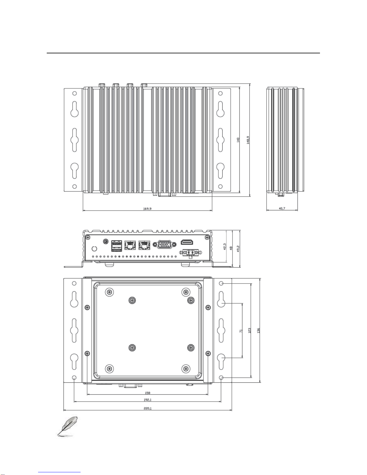
1.1 System Physical Features
Front View
Rear View

1.2 System Specificications
System Configuration
Processor
Intel® Celeron® Processor J1900 (2M Cache, up to 2.42 GHz)
Graphics
Integrated Intel® Gen7 Intel® Graphics DX 11, OGL3.2
Ethernet
RJ45 port x 2, 10/100/1000Mb TX
Memory
Supports Single Channel DDR3 1333MHz, 1 x SO-DIMM, up to
8GB system memory
Storages
Internal 2.5” HDD / SSD x1 (optional)
I/O Interface
USB 2.0
4
Ethernet port
2
COM
RS232/422/485 x 1, RS232 x 3
VGA
1
HDMI
1
Audio
1 (Line Out)
Mini-PCIe
1 (Half Size) + 1 (Full Size ) shared with mSATA
Environmental and Compliances
Operating Temperature
0 ~ 60ºC
Storage Temperature
-40 ~ 75ºC
Humidity
5~95% (Non-Condensing)
Certification Compliance
CE, FCC
Mechanical
Protection
IP30
Dimension
140 (H) x 169.9 (W) x 40.7 (D) mm
Weight
2kg
Power
Input voltage
12 VDC Input
Power On
AT / ATX supported (Defaut is ATX mode
Operating system
OS
Windows 7 / 8, WES7, Linux (Optional)
Ordering Information
EBC-310L_M2G
Intel J1900 2.0GHz, Memory DDR3 1333MHz 2GB
EBC-310L_M2G_S64G
Intel J1900 2.0GHz, Memory DDR3 1333MHz 2GB, SSD 64GB
EBC-310L_M2G_S128G
Intel J1900 2.0GHz, Memory DDR3 1333MHz 2GB, SSD 128GB
EBC-310L_M4G
Intel J1900 2.0GHz, Memory DDR3 1333MHz 4GB
EBC-310L_M4G_S64G
Intel J1900 2.0GHz, Memory DDR3 1333MHz 4GB, SSD 64GB
EBC-310L_M4G_S128G
Intel J1900 2.0GHz, Memory DDR3 1333MHz 4GB, SSD 128GB

7
Optional Modules
4G LTE & GPS module
802.11 WiFi+BT module
Memory DDR3L SO-DIMM 2GB / 4GB / 8GB
SATA 2.5” HDD 500GB / 1TB
SATA 2.5” SSD 64 / 128 / 256 GB
Power adapter DC 12V with Power cord
* Specifications are subject to change without notice
1.3 Package contents
Check your system package for the following items.
Before you begin installing your single board, please make sure that the following materials have been shipped:
1 x EBC-310L embedded box PC
2 x Wall mount brackets
1 x 2-pin terminal block power connector
If any of the above items is damaged or missing, contact your retailer.
Chapter 2: System Components
2.1 System Drawing
NOTE: Use M3*4L flat screws for wall mount.

2.2 System Front IO
IO Port
Description
Power Button with dual LED
ATX Power-on button with LEDs: Standby
mode in Red; Power-on mode in Green
USB 2.0 Ports
Double-stacked USB 2.0 type A connectors
COM 1~ COM 4
The serial port consists of a 9-pin, RS232 configured with
automatic hardware flow control D-SUB connector that
allows the connection of a serial peripheral.
COM 1 supports RS232/422/485, To switch among
RS232/422/485, use the BIOS menu.
NOTE: This system supports RS232/422/485 on COM1 port. Please refer to below table for the pin
definition. In addition, COM1 port (RS232/422/485) can be adjusted in BIOS setup utility > Advanced
Screen > Super IO Configuration.
COM1 Port Pin Definition
Pin
RS232
RS422
RS485
1
DCD
TX-
RTX-
2
RXD
RX+
N/A
3
TXD
TX+
RTX+
4
DTR
RX-
N/A
5
GND
GND
GND
6
DSR
N/A
N/A
7
RTS
N/A
N/A
8
CTS
N/A
N/A
9
NA/+5V/+12V
N/A
N/A

2.3 System Rear IO
IO Port
Description
Power Input
2-pin terminal block (+,-), +9~36VDC, AT/ATX mode support.
HDMI
The HDMI (High-Definition Multimedia Interface).
This port can support up to 1920x1080 resolutions.
VGA
The displays can support VGA up to 1600x1200 resolutions.
LAN1 and LAN2
Two RJ-45 (network) jacks with LED indicators are as described
below.
LINK/ACT (Green)
• On/Flashing: The port is linking and active in data
transmission.
• Off: The port is not linking.
SPEED (Green)
• Green: The connection speed is 1000Mbps
• Off: The connection speed is 10Mbps and 1000Mbps.
USB3.0
Two USB 3.0 type A connectors.
Line Out
Connect the audio device to this port.
11
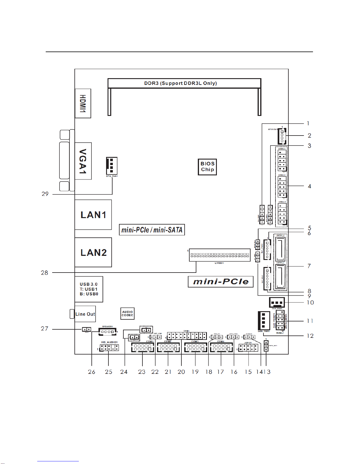
Chapter 3: Mainboard Layout

3.1 Connectors and Jumpers list
The tables below list the function of each of the board jumpers and connectors by labels shown in the above section.
The next section in this chapter gives pin definitions and instructions on setting jumpers.
Label
Function
Note
1. PNL_PWR1
Panel LVDS VDD Power Selection
2. ATX12V1
+9V~+36VDC System ATX Power Input
3. BKT_PWR1
LVDS Backlight Power Selection
4. USB0_1, USB2_3, USB4_5
USB2.0 pin header x 3
5. MSATA_SEL1
SATAII_2 or mSATA Selection
6. BLT_PWR1
Panel Inverter Power Control
7. SATAII_1, SATAII_2
Serial-ATA II Connector x 2
8. BLT_VOL1
Backlight & Amp Volume Control
9. BLT_PWM1
Backlight Control Level
10. CHA_FAN1
3-Pin Chassis FAN Connector
11. PANEL1
System Panel Header
12. SATA_PWR1
SATA Power Output Connector
13. JGPIO_SET1
GPIO Default Setting
14. CLRCMOS1
Clear CMOS Header
15. JGPIO1
Digital Input / Output Pin Header
16. JGPIO_PWR1
Digital Input / Output Power Select
17. COM4
COM4 Port Header
18. PWR_JP1
ATX/AT Mode Selection
19. COM3
COM3 Port Header
20. TPM1
TPM Header
21. COM2
COM2 Port Header
22. SET_CM1
COM1 Pin9 PWR Setting
23. COM1
COM1 Port Header
24. CI1 and CI2
Chassis Intrusion Headers x 2
25. HD_AUDIO1
Front Panel Audio Header
26. SPEAKER1
3W Audio AMP Output Wafer
27. BUZZ1
2-Pin Buzzer Header
28. LVDS1
LVDS Panel Connector
29. CPU_FAN1
4-Pin CPU FAN Connector

13
3.2 Jumper Settings
The illustration shows how jumpers are setup. When the jumper cap is placed on pins, the jumper is “Short”. If no jumper
cap is placed on pins, the jumper is “Open”. The illustration shows a 3-pin jumper whose pin1 and pin2 are “Short” when
jumper cap is placed on these 2 pins.
PNL_PWR1 (Panel LVDS VDD Power Selection):
Use this to set up the VDD power of the LVDS connector.
BKT_PWR1 (LVDS Backlight Power Selection)
Use this to set up the backlight power of the LVDS connector.
Setting
Description
1-2
+5V
2-3
+12V
3-4
+12V
4-5
DC_IN Power
MSATA_SEL1 (SATAII_2 or mSATA Selection)
Setting
Description
1-2
+3V
2-3
+5V
3-4
+5V
4-5
+12V
Setting
Description
1-2
SATAII_2 + mini-PCIe
2-3
mSATA, SATAII_2 no function

BLT_PWM1 (Backlight Control Level)
JGPIO_SET1 (GPIO Default Setting)
CLRCMOS1 (Clear CMOS Header)
CLRCMOS1 allows you to clear the data in CMOS. To clear and reset the system parameters to default setup, please
turn off the computer and unplug the power cord from the power supply. After waiting for 15 seconds, use a jumper cap
to short pin2 and pin3 on CLRCMOS1 for 5 seconds. However, please do not clear the CMOS right after you update the
BIOS. If you need to clear the CMOS when you just finish updating the BIOS, you must boot up the system first, and
then shut it down before you do the clear-CMOS action. Please be noted that the password, date, time, user default
profile and MAC address will be cleared only if the CMOS battery is removed.
JGPIO_PWR1 (Digital Input / Output Power Select)
PWR_JP1 (ATX/AT Mode Selection)
SET_CM1 (COM1 Pin9 PWR Setting)
Setting
Description
1-2
+3.3V
2-3
+5V
Setting
Description
1-2
Pull-High
2-3
Pull-Low
Setting
Description
1-2
Default
2-3
Clear CMOS
Setting
Description
1-2
+12V
2-3
+5V
Setting
Description
1-2
AT Mode
2-3
ATX Mode
Setting
Description
1-2
+5V
2-3
+12V

3.3 Connectors
ATX12V1 (+9V~+36VDC System ATX Power Input)
Pin
Signal
1
+5V
2
+12V
3
+12V
4
DC_IN Power
USB0_1, USB2_3, USB4_5 (USB2.0 pin header x 3)
BLT_PWR1 (Panel Inverter Power Control)
Pin
Signal
1
GND
2
GND
3
CON_LBKLT_CTL
4
CON_LBKLT_EN
5
LCD_BLT_VCC
6
LCD_BLT_VCC
SATAII_1, SATAII_2 (Serial-ATA II Connector x 2)
SATA 7-pin signal connector for HDD/SSD. The interface signal is SATA 3.0 Gbps.
Pin
Signal
1
GND
2
SATATXP
3
SATATXN
4
GND
5
SATARXN
6
SATARXP
7
GND

BLT_VOL1 (Backlight & Amp Volume Control)
Pin
Signal
1
GPIO_VOL_UP
2
GPIO_VOL_DW
3
PWRDN
4
GPIO_BLT_UP
5
GPIO_BLT_DW
6
GND
7
GND
PANEL1 (System Panel Header)
This header accommodates several system front panel functions.
WARNING: Connect the power switch, reset switch and system status indicator on the chassis to this
header according to the pin assignments below. Note the positive and negative pins before connecting
the cables.
PWRBTN (Power Switch):
Connect to the power switch on the chassis front panel. You may configure the way to turn off your system using the
power switch.
RESET (Reset Switch):
Connect to the reset switch on the chassis front panel. Press the reset switch to restart the computer if the computer
freezes and fails to perform a normal restart.
PLED (System Power LED):
Connect to the power status indicator on the chassis front panel. The LED is on when the system is operating. The LED
keeps blinking when the sys-tem is in S1 sleep state. The LED is off when the system is in S3/S4 sleep state or powered
off (S5).
SATA_PWR1 (SATA Power Output Connector)

17
JGPIO1 (Digital Input / Output Pin Header)
COM1/2/3/4 (COM Port Header)
NOTE: This system supports RS232/422/485 on COM1 port. Please refer to below table for the pin
definition. In addition, COM1 port (RS232/422/485) can be adjusted in BIOS setup utility > Advanced Screen
> Super IO Configuration.
COM1 Port Pin Definition
Pin
Signal
Pin
Signal
1
SIO_GP24
2
SIO_GP20
3
SIO_GP25
4
SIO_GP21
5
SIO_GP26
6
SIO_GP22
7
SIO_GP27
8
SIO_GP23
9
JGPIO_PWR
10
GND
Pin
Signal
Pin
Signal
2
RRXD
1
DDCD#
4
DDTR#
3
TTXD
6
DDSR#
5
GND
8
CCTS#
7
RRTX#
10
DUMMY
9
DUMMY
Pin
RS232
RS422
RS485
1
DCD
TX-
RTX-
2
RXD
RX+
N/A
3
TXD
TX+
RTX+
4
DTR
RX-
N/A
5
GND
GND
GND
6
DSR
N/A
N/A
7
RTS
N/A
N/A
8
CTS
N/A
N/A
9
NA/+5V/+12V
N/A
N/A

TPM1 (TPM Header)
This connector supports Trusted Platform Module (TPM) system, which can securely store keys, digital certificates,
passwords, and data. A TPM system also helps enhance network security, protects digital identities, and ensures
platform integrity.
CI1 and CI2 (Chassis Intrusion Headers x 2)
This motherboard supports CASE OPEN detection feature that detects if the chassis cover has been removed. This
feature requires a chassis with chassis intrusion detection design.
HD_AUDIO1 (Front Panel Audio Header)
SPEAKER1 (3W Audio AMP Output Wafer)
Pin
Signal
1
SPK L-
2
SPK L+
3
SPK R-
4
SPK R+
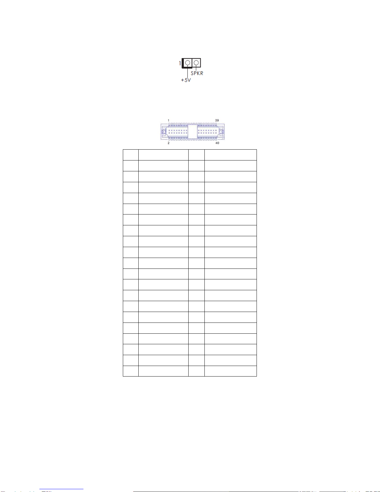
BUZZ1 (2-Pin Buzzer Header)
LVDS1 (LVDS Panel Connector)
Pin
Signal
Pin
Signal
2
LCD_VCC
1
LCD_VCC
4
N/A
3
+3V
6
LVDS_A_DATA0#
5
N/A
8
GND1
7
LVDS_A_DATA0
10
LVDS_A_DATA1
9
LVDS_A_DATA1#
12
LVDS_A_DATA2#
11
GND6
14
GND2
13
LVDS_A_DATA2
16
LVDS_A_DATA3
15
LVDS_A_DATA3#
18
LVDS_A_CLK#
17
GND7
20
GND3
19
LVDS_A_CLK
22
LVDS_B_DATA0
21
LVDS_B_DATA0#
24
LVDS_B_DATA1#
23
GND8
26
GND4
25
LVDS_B_DATA1
28
LVDS_B_DATA2
27
LVDS_B_DATA2#
30
LVDS_B_DATA3#
29
DPLVDD_EN
32
GND5
31
LVDS_B_DATA3
34
LVDS_B_CLK
33
LVDS_B_CLK#
36
CON_LBKLT_EN
35
GND9
38
LCD_BLT_VCC
37
CON_LBKLT_CTR
40
LCD_BLT_VCC
39
LCD_BLT_VCC
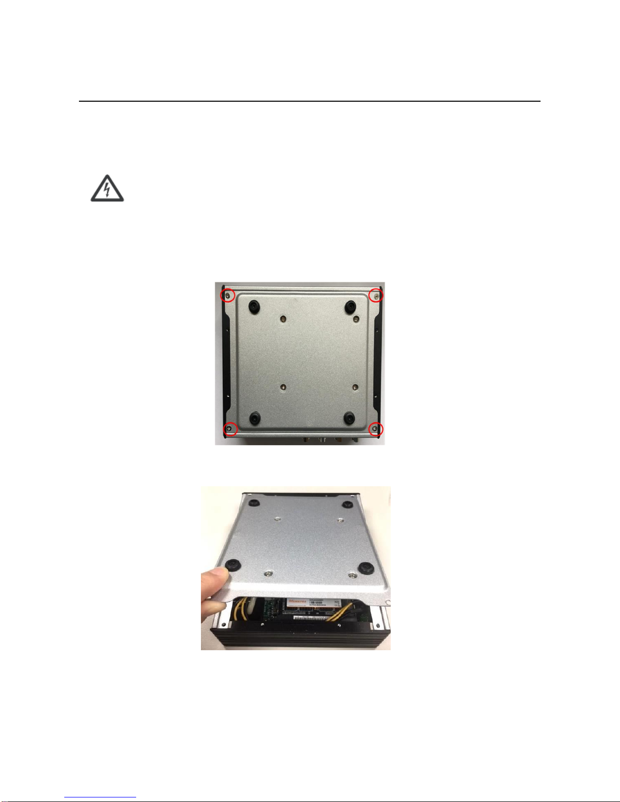
Chapter 4: Hardware Setup
4.1 Preparing the Hardware Installation
To access some components and perform certain service procedures, you must perform the following procedures first.
WARNING: To reduce the risk of personal injury, electric shock, or damage to the equipment, remove the
power cord to remove power from the server. The power switch button does not completely shut off
system power. Portions of the power supply and some internal circuitry remain active until power is
removed.
1. Unpowered the EBC-310L and remove the power cord.
2. Turn the device upside down.
3. Unscrew the 4 rubber feet from the bottom cover.
4. Open the cover.
This manual suits for next models
6
Table of contents


