GE Capital ZDT800SIFII User manual

Installation
Instructions
31-31530
09-13 GE
Built-In Dishwashers
*Custom front panel models include a kit that
contains a template, hardware and panel
installation instructions. Refer to the kit
instructions when installing the custom panel.

CONTENTS
Installation Preparation
Parts Supplied......................................................................................3
Materials You Will Need..................................................................3
Tools You Will Need..........................................................................3
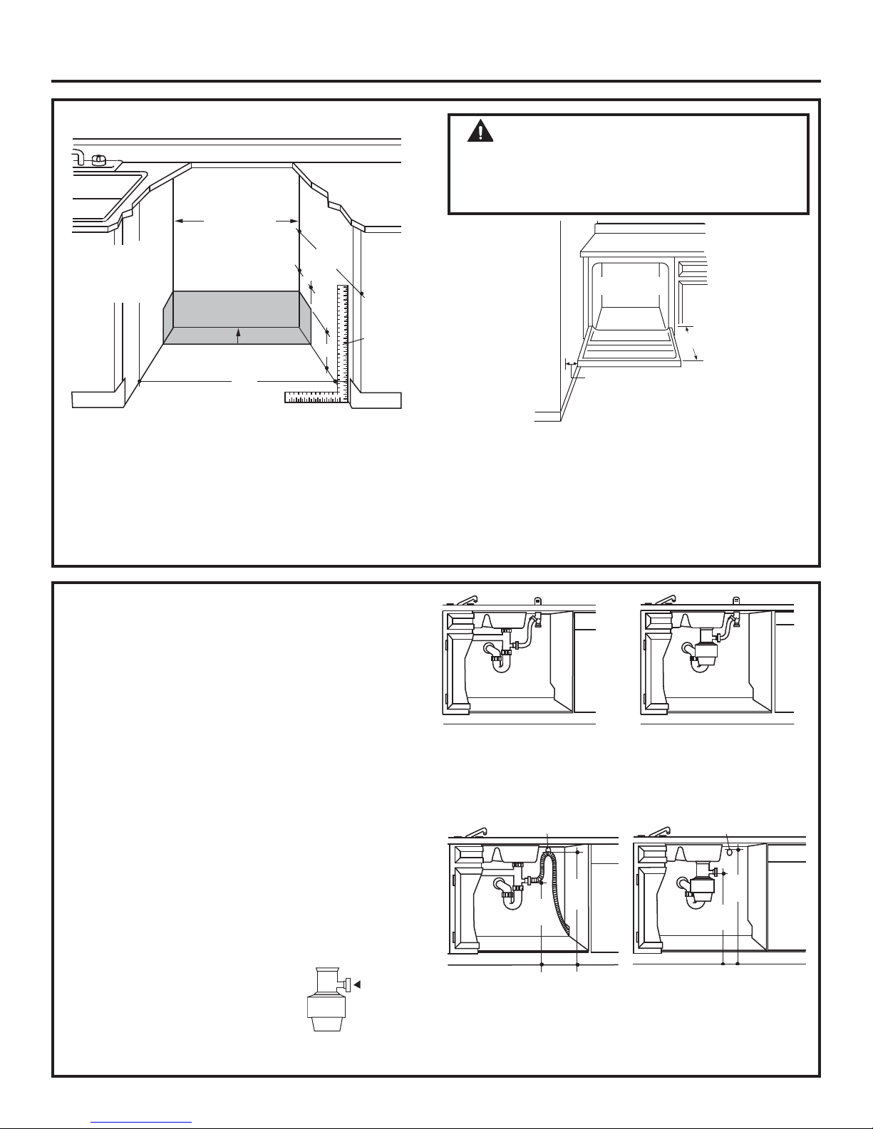
Prepare Dishwasher Enclosure...................................................4
Drain Requirements..........................................................................4
Prepare Electrical Wiring................................................................5
Prepare Hot Water Line..................................................................6
Dishwasher Installation
Step 1, Preparation ...........................................................................7
Step 2, Check Door Balance.........................................................7
Step 3, Remove Wood Base, Install Leveling Legs.............7
Step 4, Remove Toekick..................................................................7
Step 5, Position Sound Barrier.....................................................7
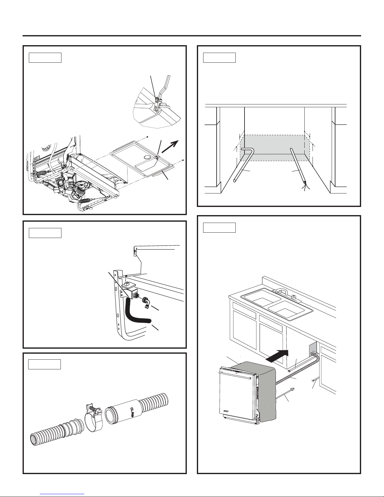
Step 6, Remove Floor Protect ......................................................8
Step 7, Install 90° Elbow.................................................................8
Step 8, Install Drain Hose to Drain Loop.................................8
Step 9, Position Water Line and House Wiring....................8
Step 10, Install Drain Hose Through Cabinet .......................8
Step 11, Slide Dishwasher Three-Fourths of the
Way Into Cabinet...............................................................................9
Step 12, Install Trim Pieces............................................................9
Step 13, Install Mounting Brackets ...........................................9
Step 14, Push Dishwasher Into Final Position................... 10
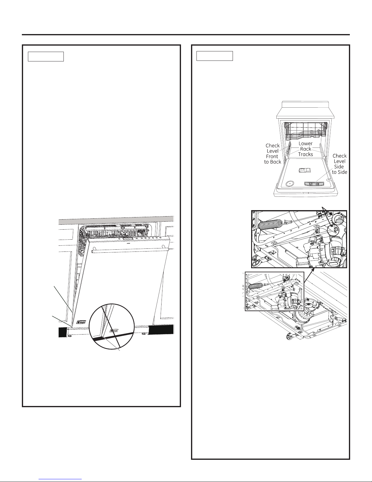
Step 15, Level Dishwasher ......................................................... 10
Step 16, Position Dishwasher, Secure to Countertop or
Cabinet................................................................................................. 11
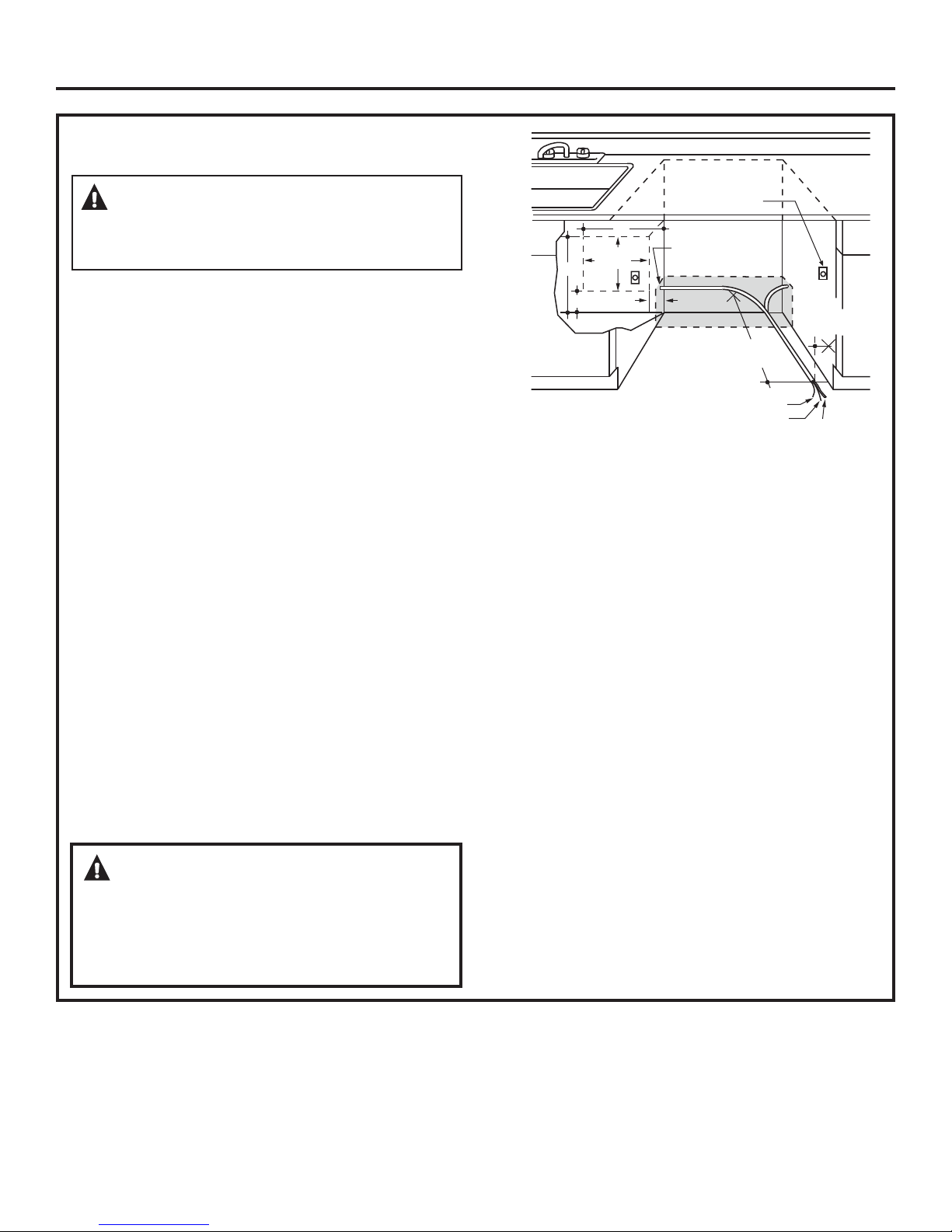
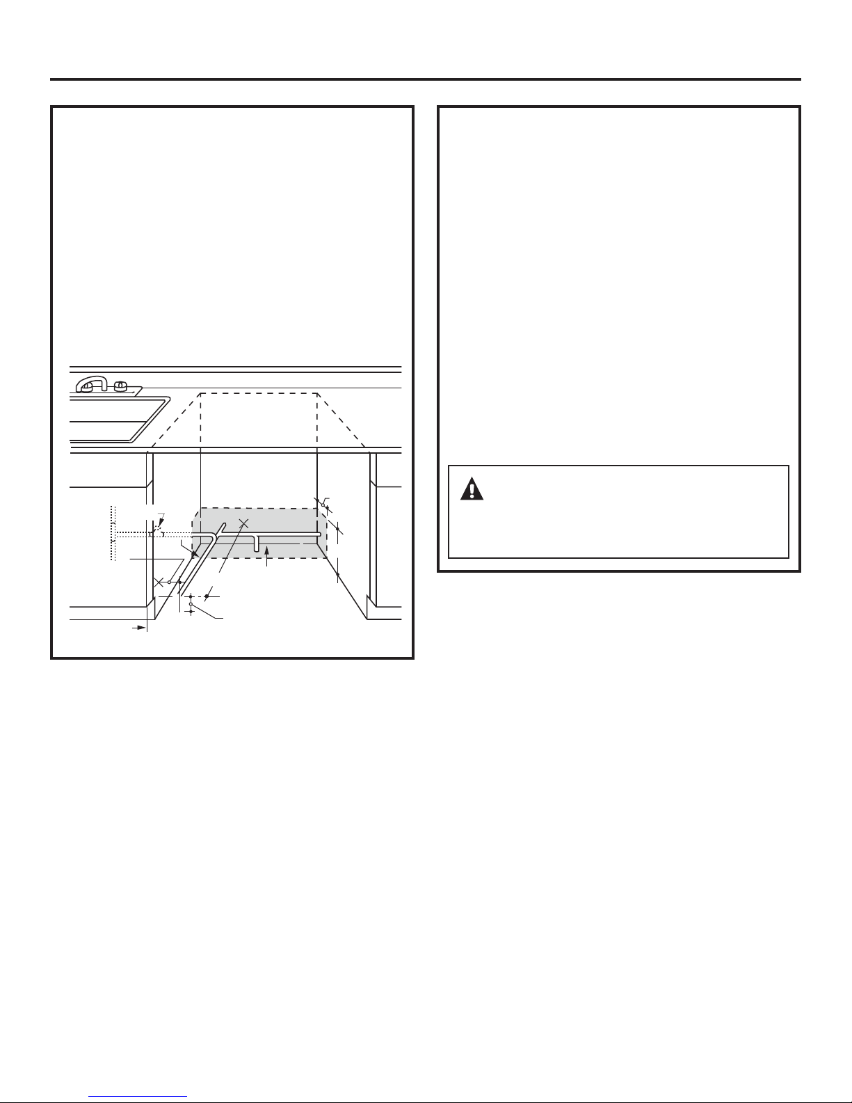
Step 17, Connect Water Supply............................................... 11
Step 18, Connect Drain Line................................................11,12
Step 19, Connect Power Supply............................................... 12
Step 20, Pretest Checklist ........................................................... 13
Step 21, Dishwasher Wet Test.................................................. 13
Step 22, Replace Floor protect................................................. 13
Step 23, Position Insulation, Pre-Toekick and
Sound Barrier ................................................................................... 14
Step 24, Replace Toekick............................................................. 14
Step 25, Literature.......................................................................... 14
Safety Information
BEFORE YOU BEGIN
Read these instructions completely and carefully.
•
IMPORTANT³ Observe all governing codes
and ordinances.
•
Note to Installer³ Be sure to leave these
instructions for the consumer’s and local
inspector’s use.
• Note to Consumer³ Keep these instructions with
your Owner’s Manual for future reference.
•Skill Level³ Installation of this dishwasher
requires basic mechanical and electrical skills. Proper
installation is the responsibility of the installer.
Product failure due to improper installation is not
covered under the GE Appliance Warranty. See
warranty information.
•Completion Time³WR+RXUV
New installations require more time than replacement
installations.
•
IMPORTANT³ The dishwasher MUST be
installed to allow for future removal from the enclosure
if service is required.
Care should be exercised when the appliance is installed
or removed, to reduce the likelihood of damage to the
power supply cord.
If you received a damaged dishwasher, you should
immediately contact your dealer or builder.
Optional Accessories – See the Owner’s Manual for
available custom panel kits.
READ CAREFULLY.
.((37+(6(,16758&7,216.
FOR YOUR SAFETY
Read and observe all CAUTIONS and WARNINGS
shown throughout these instructions. While
performing installations described in this booklet,
gloves, safety glasses or goggles should be worn.
For Monogram local service in your area, 1.800.444.1845.
For Monogram parts and accessories, call 1.800.626.2002.
For Monogram parts and accessories in Canada, call
1.800.561.3344.
2

PARTS SUPPLIED IN INSTALLATION
PACKAGE:
• Junction box cover and #10 hex-head screw
• Hose clamp
• Drain hose (approximately 78” long)
• Drain hose hanger
• 2 #8-18 hex head screws to secure brackets to
washer tub frame
• 1 top trim piece
• 2 side trim pieces
• 2 mounting brackets for wood countertops
or side cabinets
• 2 #8-18 x 5/8” Phillips special head screws,
to secure dishwasher to underside of
countertop or to side cabinets
• Literature, samples and/or coupons
TOOLS YOU WILL NEED:
• Phillips-head screwdriver
• 5/16” and 1/4” nutdriver
• 6” Adjustable wrench
• Level
• Carpenter’s square
• Measuring tape
• Safety glasses
• Flashlight
• Bucket to catch water when flushing the line
• 15/16” socket (optional for skid removal)
• Gloves
• Pliers
For New Installations Only:
• Tubing cutter
• Drill and appropriate bits
• Hole saw set
MATERIALS YOU WILL NEED:
• 90° elbow (3/4”hose internal thread on one end,
opposite end sized to fit water supply)
• UL-listed wire nuts (3)
• Masking Tape
Materials For New Installations Only:
• Air gap for drain hose, if required
• Waste tee for house plumbing, if applicable
• Electrical cable or power cord depending on your
model, quick connect power cords are availble.
• Screw-type hose clamps
• Strain relief for electrical connection
• Hand shut-off valve (recommended)
• Hot Water Line–3/8” minimum, copper tubing
(including ferrule, compression nut) or GE Part #
WX28X326, flexible braided hose.
• GPF12 or WD24X10065 drain hose (12’ long), if needed.
Installation Preparation
3
Hole Saw Set
Measuring Tape
Tubing Cutter
Drill and Bits
Phillips-Head
Screwdriver
15/16” Socket
1/4” and 5/16”
Nutdriver
6” Adjustable
Wrench
Bucket
Flashlight
Gloves
Carpenter’s
Square
Safety Glasses
Level
'UDLQ+RVH
+RVH&ODPS
+H[+HDG0RXQWLQJ
Bracket Screws
'UDLQ+RVH+DQJHU
Junction
%R[&RYHU
#10
+H[+HDG
Junction
%R[6FUHZ
1/2" long
Mounting
Brackets
#8 Phillips
Special
+HDG6FUHZV
5/8" long Literature
Top Trim Piece
Side Trim Pieces
+RW:DWHU/LQH
Strain Relief
Optional
'UDLQ+RVH
GPF12 or
WD24X10065
+RVH&ODPSV
Waste Tee
Electrical Cable
(or Power Cord, if applicable)
Wire Nuts (3)
90°Elbow Masking Tape
(if applicable)
+DQG
6KXW2ȹ
Valve
Air Gap
Pliers

35(3$5(',6+:$6+(5(1&/2685(
• The rough cabinet opening must be at least 24” deep,
24” wide and approximately 34-1/2” high from floor to
underside of the countertop.
• The dishwasher must be installed so that drain hose is no
more than 12’ in length for proper drainage.
• The dishwasher must be fully enclosed on the top,
sides and back, and must not support any part of the
enclosure.
WARNING
To reduce the risk of electric shock, fire, or injury
to persons, the installer must ensure that the
dishwasher is completely enclosed at the time of
installation.
CLEARANCES:
•When installed into a corner, allow 2” min. clearance
between dishwasher and adjacent cabinet, wall or other
appliances. Allow 28-3/8” min. clearance from the front of
the dishwasher for door opening. Figure B.
•Allow at least 6” between dishwasher and range or oven
appliances.
24"
Min.
This Wall Area
must be Free
of Pipes or
wires
Plumbing and Electric Service
Must Enter Inside This Area
4"
24"
Min.
6"
Cabinets
Square
and
Plumb
+
34-1/2" 1/4"
Underside of
Countertop
to Floor
Figure A
33-1/2” to 34-3/4”
Underside of
Countertop
to Floor
Clearance for Door
Opening 2" Minimum
Countertop
Dishwasher
28-3/8"
Figure B
DRAIN REQUIREMENTS
• Follow local codes and ordinances.
• Do not exceed 15’ distance to drain.
NOTE : Air gap must be used, if waste tee or disposer
connection is less than 18” above floor to prevent
siphoning.
'(7(50,1('5$,10(7+2'
The type of drain installation depends on the following
questions.
• Do local codes or ordinances require an air gap?
• Is waste tee less than 18” above floor?
If the answer to either question is YES, Method 1
MUST be used.
•If the answers are NO, either method may be used.
CABINET PREPARATION
• Drill a 1-1/2” diameter hole in the cabinet wall within
the shaded areas shown in Figure A for the drain hose
connection. The hole should be smooth with no sharp
edges.
IMPORTANT – When connecting
drain line to disposer, check to be
sure that drain plug has been
removed. DISHWASHER WILL NOT DRAIN IF PLUG IS LEFT IN
PLACE.
Method 1 – Air Gap with Waste Tee or Disposer
An air gap must be used when required by local codes and
ordinances. The air gap must be installed according to
manufacturer’s instructions.
0HWKRG²´+LJK'UDLQ/RRSµZLWK:DVWH7HHRU'LVSRVHU
Tip: Avoid unnecessary service call charges.
Always be sure disposer drain plug has been removed
before attaching dishwasher drain hose to the disposer.
Figure D
32"
Min.
18"
Min.
Drain Hose Hanger
Figure C
Remove
Drain
Plug
32"
Min.
18"
Min.
Drain Hose Hanger
4

Installation Preparation
For models equipped with power cord: Do not modify the
plug provided with the appliance; if it will not fit the outlet,
have a proper outlet installed by a qualified technician.
Cabinet Preparation & Wire Routing
•The wiring may enter the opening from either side, rear or
the floor within the shaded area illustrated above in Figure
E and defined in Figure A.
• Cut a 1-1/2" maximum diameter hole to admit the
electrical cable. Edges of hole should be smooth and
rounded. Permanent wiring connections may pass
through the same hole as the drain hose and hot water
line, if convenient. If cabinet wall is metal, the hole edge
must be covered with a bushing.
NOTE: Power cords with plug must pass through a
separate hole.
Electrical Connection to Dishwasher
Electrical connection is on the right front of dishwasher.
• For permanent connections the cable must be routed as
shown in Figure E. Cable must extend a minimum of 24"
from the rear wall.
• For power cord connections, install a 3-prong grounding
type receptacle in the sink cabinet rear wall, 6" min. or 18"
maximum from the opening, 6" to 18" above the floor.
• Use the Power Cord Kit for your dishwasher model.
PREPARE ELECTRICAL WIRING
Electrical Requirements
• This appliance must be supplied with 120V, 60 Hz., and
connected to an individual properly grounded branch
circuit, protected by a 15- or 20-ampere circuit breaker
or time-delay fuse.
• Wiring must be 2 wire with ground and rated for 75°C
(167°F).
• If the electrical supply does not meet the above
requirements, call a licensed electrician before
proceeding.
Grounding Instructions–Permanent Connection
This appliance must be connected to a grounded metal,
permanent wiring system, or an equipment-grounding
conductor must be run with the circuit conductors and be
connected to the equipment-grounding terminal or lead on
the appliance.
Grounding Instructions–Power Cord Models
This appliance must be grounded. In the event of a
malfunction or breakdown, grounding will reduce the risk
of electric shock by providing a path of least resistance
for electric current. This appliance is equipped with a
cord having an equipment-grounding conductor and
a grounding plug. The plug must be plugged into an
appropriate outlet that is installed and grounded in
accordance with all local codes and ordinances.
White
18"
6"
24"
from Wall
3"
from
Cabinet
Alternate
Receptacle
Location
Ground
Black
1-1/2" Dia. Hole (Max.)
18"
6"
Receptacle
Location
Area
Figure E
WARNING:
FOR PERSONAL SAFETY: Remove house fuse or open circuit
breaker before beginning installation. Do not use an extension
cord or adapter plug with this appliance.
WARNING:
The improper connection of the equipment grounding
conductor can result in a risk of electric shock. Check
ZLWKDTXDOL¿HGHOHFWULFLDQRUVHUYLFHUHSUHVHQWDWLYH
if you are in doubt that the appliance is properly
grounded.
5

Water Line Connection
• If using a flexible braided supply hose, label the hose
with the installation date to use as reference. Flexible
braided hoses should be replaced in 5 years.
• Turn off the water supply.
• Install a hand shut-off valve in an accessible location,
such as under the sink. (Optional, but strongly
recommended and may be required by local codes.)
• Water connection is on the left side of the dishwasher.
Install the hot water inlet line, using no less than 3/8”
copper tubing or a flexible braided hose. Route the line
as shown in Figure F and extend forward at least 19”
from rear wall.
• Adjust water heater for 120°F to 140°F temperature.
• Flush water line to clean out debris.
• The hot water supply line pressure must be 20-120 PSI.
Turn page to begin dishwasher installation.
Installation Preparation
35(3$5(+27:$7(5/,1(
NOTE: GE recommends copper tubing for the water
line, but if you choose to use flexible hose, use GE’s
WX28X326, flexible braided hose.
•The water supply line (3/8” copper tubing or flexible
braided hose) may enter from either side, rear or floor
within the shaded area shown in Figure F.
• The water supply line may pass through the same
hole as the electrical cable and drain hose. Or, cut an
additional 1-1/2" diameter hole to accommodate the
water line. If power cord with plug is used, water line
must not pass through power cord hole.
Figure F
6"
4"
Cabinet Face
Shut-off
Valve
2" From Floor
19" From Wall
2"
From
Cabinet
1-1/2" Dia.
Hole
Hot
CAUTION:
Do not remove wood base until you are ready to install
the dishwasher. The dishwasher will tip over when the
door is opened if base is removed.
6

REMOVE TOEKICK
• Remove the 2 toekick screws and toekick. Set aside for
use in Step 24.
STEP 1 PREPARATION
Locate the items in the installation package:
• Screws
• Junction box cover
• Drain hose and clamp
• Mounting brackets
• Trim pieces (on some models)
• Drain hose hanger
• Owner’s Manual
• Product samples and/or coupons
Dishwasher Installation
STEP 3
REMOVE WOOD BASE,
INSTALL LEVELING LEGS
IMPORTANT – Do not kick off wood base!
Damage will occur.
• Move the dishwasher close to the installation location
and lay it on its back.
• Remove the 4 leveling legs on the underside of the
wood base with a 15/16” socket wrench.
• Discard base and 2 leveling legs.
• Screw front 2 leveling legs back into the dishwasher
frame, approximately 1/2” from frame as shown.
NOTE: The dishwasher has rear adjustable leveling
wheels, and will not require the 2 rear leveling legs.
STEP 2 &+(&.'225%$/$1&(
NOTE: If installing a
Custom Door Panel
(available on some
models), please follow
the instructions found in
the Custom Door Panel
kit.
• With dishwasher on
the wood base, check
the door balance by
opening and closing
the door.
• Door is properly
balanced if, when opened, it self closes within 20° from
vertical, stays in position from 20° to 70° and falls fully
open beyond 70°.
• If necessary increase or decrease tension as shown.
Some models will have 2 springs on one side and 1
spring on the other side. Latch door and adjust springs
to correct balance.
Tip: Make sure door opens and closes smoothly.
Check door opening and closing. If door does not open
easily or falls too quickly, check spring cable routing. The
cable is held in place by “shoulders” on the pulley. Check
to be sure cable has not slipped over the pulley shoulders
and is routed as shown.
Side View
Make sure pulley cables
are within pulley shoulders
Front View
Custom
door
panel
Spring
hooked
to screw
inside leg
Increase
Tension
Decrease
Tension
)LJXUH+
Approx.
1/2"
Figure I
Figure J
Sound Barrier
Bottom Front View
Tape
POSITION SOUND BARRIER
(on some models)
Skip this step if the
sound barrier is not
assembled
to the dishwasher.
Lift the sound barrier
and tape to the door
front with masking
tape. This will hold the
sound barrier up and
out of the way during
installation. Figure K
STEP 4
STEP 5
7
Figure G
Door
closes
within
20°
Door stays in
position from
20° to 70°
Door falls fully
open beyond 70°
Side View
Figure G
Toekick
Remove 2
Toekick Screws

STEP 9
POSITION WATER LINE AND
+286(:,5,1*
• Position water supply line and house wiring on the
floor of the opening to avoid interference with base of
dishwasher and components under dishwasher.
STEP 10
,167$//'5$,1+26(
7+528*+&$%,1(7
• Position dishwasher in front of cabinet opening. Insert
drain hose into the hole in cabinet side. If a power cord
is used, guide the end through a separate hole.
Tip: Prevent unnecessary service call charges for fill,
drain or noise concerns.
Position utility lines so they do not interfere with anything
under or behind the dishwasher.
Dishwasher Installation
STEP 6 REMOVE FLOOR PROTECT
• Disconnect leak sensor wire
(on some models).
• Remove 2 screws from front of the
Floor Protect with a ¼” driver.
• Rotate Floor Protect outward and lift
out of the mounting tabs.
• Set aside for use in Step 22.
Floor Protect
Leak Sensor
Figure L
STEP 7 INSTALL 90° ELBOW
• Thread 90° elbow
onto the water valve.
• Do not overtighten
elbow. Water valve
bracket could bend
or water valve fitting
could break.
• Position the end of the
elbow to face the rear
of the dishwasher.
Figure M
Water Valve
Bracket
Fill Hose
Front of dishwasher
STEP 8 ,167$//'5$,1+26(72
DRAIN LOOP
Connect drain loop end to drain hose using the screw
clamp as shown in the figure.
NOTE: The high drain loop on the side of the tub is
designed for better wash performance. Do not remove
from the side of the tub.
Figure N
Figure O
Water
Line House
Wiring
4" 4"
6"
6"
Power Cord
(If Used)
Insulation
Blanket Water
Line
Maximum Drain Hose
Length 15'
House
Wiring
Drain
Hose
Figure P
8
90° Elbow
Squeeze connector at top
to release snap feature

STEP 12
INSTALL TRIM PIECES
In this step you will need the trim pieces set aside in Step 1.
• Select the top trim piece (See Figure R) and line up
center to the top latch. Press the trim piece onto the
tub flange moving from one side to the other.
• Select the left trim piece (see Figure R). Align top edge
with the top trim and press it onto the left side of the
tub flange moving from the top to the bottom. Repeat
for the right side tub flange trim piece. (See Figure R for
right side trim piece.)
STEP 13
INSTALL MOUNTING BRACKETS
You will need the mounting brackets and 2 #8 hex-head
screws set aside in Step 1.
You must install the mounting brackets onto the
dishwasher tub frame top or sides prior to sliding
the dishwasher into place under the countertop. This
dishwasher is capable of a true-flush installation at a
24” deep opening. The mounting brackets have several
available attachment positions to accommodate different
cabinet constructions.
Install mounting brackets on top if the underside of
countertop is wood or wood-like material that accepts
screws:
IMPORTANT - After installing brackets and before
closing the dishwasher door, adjust the brackets by
bending them up as needed, so that they do not contact
the top of the dishwasher door and cause damage.
• If you are installing the dishwasher under a counter
with a short overhang, the countertop brackets may
extend beyond the edge of the counter. If this is the case,
remove the excess length by repeatedly bending the
brackets at the front notch only until they break.
Install mounting brackets on sides if the countertop
is granite or similar material that will not accept wood screws:
• Break off front portion of the tab with pliers at the
location shown.
• Position the left-hand side bracket as shown. Repeat
with the right bracket.
Dishwasher Installation
6/,'(',6+:$6+(57+5(()2857+6
2)7+(:$<,172&$%,1(7
IMPORTANT – Do not push against front panel with
knees. Damage will occur.
• Grasp the sides of the front panel and slide dishwasher
into the opening a few inches at a time.
• As you proceed, pull the drain hose through the opening
under the sink. Stop pushing when the dishwasher
extends about 6 inches forward of adjacent cabinets.
• Make sure drain hose is not kinked under or behind the
dishwasher.
• Make certain the house wiring, drain line and water line
do not interfere with components under dishwasher.
Dishwasher
tub frame
#8 Bracket
Screw
Bracket
Bend and break here
after installing if
counter has a short
overhang.
Top Mounting
Figure S
Bracket
Dishwasher
tub frame
#8 Bracket
Screw as
supplied
Side Mounting
Bend and break
here if necessary
Figure T
Side Trim Figure R
Side
Trim
Top View
Side
Trim
Top Trim
STEP 11
Figure Q
Do not push against
front door panel with
knee. Damage to the
door panel will occur.
9

Dishwasher Installation
STEP 14
386+',6+:$6+(5,172
FINAL POSITION
• Check the tub insulation blanket, if equipped, to be sure it is
smoothly wrapped around the tub. It should not be “bunched
up” and it must not interfere with the door springs. If the
insulation is “bunched up” or interfering with the springs,
straighten and re center the blanket prior to sliding the
dishwasher into its final position.
• Slide the dishwasher into the final position by pushing on
the sides of the door panel. Do not use a knee or push on the
center of the panel. If you do, damage to the panel will likely
result.
IMPORTANT –Before opening the dishwasher
door, be certain the edges of the dishwasher door panel are
behind the face of the adjacent cabinet and not up against the
cabinet face. Refer to Figure U. If the dishwasher door is opened
when the edge of the door is against the face of the cabinet,
dishwasher door damage and cabinet damage will occur.
• Open and close the dishwasher door to be sure it operates
smoothly, and does not rub on the adjacent cabinet.
Tip: Prevent unnecessary service charges for panel
damage or wash performance.
Check dishwasher alignment prior to opening dishwasher door
to prevent panel damage.
Make sure utility lines are not trapped or crushed behind
dishwasher. Crushed lines will restrict water flow.
STEP 15
/(9(/',6+:$6+(5
IMPORTANT – Dishwasher must be level for proper dish
rack operation, wash performance and door operation. The
dishwasher must be leveled left to right and front to back.
This ensures the dish racks will not roll in or out on their own,
circulation water will flow to the pump inlet, and the door will
close without hitting the side
of the tub.
• Remove the lower dish
rack and place a level on
the door and lower rack
track as shown in Figure V.
• The height of the wheels
are adjusted from the front
of the dishwasher along
with the 2 front legs on
the bottom of the
dishwasher. Begin the
leveling process with the
front legs by individually
turning the front 2 legs.
By adjusting the
front legs first,access
to the rear leveling
bolts is maximized
easing rear wheel
adjustment. When
the front legs are
adjusted to a height
resulting in an
appropriate gap to
the upper cabinet,
proceed to adjust
the rear leveling
bolts and wheels.
Individually turn
the 2 bolts to
adjust the rear
wheels. Slowly
rotate the 2 bolts
counter clockwise
to raise the
dishwasher, and
clockwise to lower it. Continue to adjust the feet and wheels
until the dishwasher is level as illustrated in Figure W.
• The dishwasher is properly leveled when the level indicator
is centered left to right and front to back. Also, the dishwasher
door should close without hitting the side of the tub.
• Replace the lower rack.
• Pull each rack out, about halfway. Check to be sure it does
not roll back or forward on the door. If the rack moves, adjust
leveling legs.
Tip: Prevent unnecessary service charges. Verify dishwasher
is leveled.
Pull the dish racks half way out. They should stay put. Open and
close the door. The door should fit in the tub opening without
hitting the side of the tub. If the racks roll on their own, or the
door hits the side of tub, re level the dishwasher.
Figure V
Figure W
10
Adjust
Door Catches
on Cabinet Frame
Incorrect Alignment
will result in door damage
Correct
Alignment
Door Fits
and Swings back
behind cabinet frame
Figure U

326,7,21',6+:$6+(5
SECURE TO COUNTERTOP OR
CABINET
In this step you will need the 2 Phillips special head screws
from the screws set aside in Step 1.
The dishwasher must be secured to the countertop or the
cabinet sides. When the underside of the countertop is wood,
use Method 1. Use Method 2 when the underside of the
countertop is made of a material, such as granite, that will
not accept wood screws.
IMPORTANT – Prevent door panel and control
panel damage. Dishwasher must be positioned so the front
panel and control panel do not contact the adjacent
cabinets or countertop. Mounting screws must be driven
straight and flush. Protruding screw heads could scratch the
door panel or control panel and interfere with door
operation.
Method 1
Secure dishwasher to underside of wood countertop.
• Recheck alignment of the dishwasher in the cabinet. Refer
to Steps 14 and 15. Door panel and/or control panel must
not hit cabinets or countertop.
• Fasten the dishwasher to the underside of the countertop
with the 2 Phillips special head screws. Refer to figure.
Make certain screws are driven straight and flush to
prevent panel damage.
Method 2
Secure dishwasher to cabinet sides.
• Recheck alignment of the dishwasher in the cabinet. Refer
to Steps 14 and 15. Door panel and/or control panel must
not hit cabinets or countertop. Remove plug buttons. Do
not discard.
• Remove plug buttons. Do not discard.
• Fasten the dishwasher to the adjacent cabinets with the
2 Phillips special head screws provided. Refer to Figure
X. Make certain screws are driven straight and flush to
prevent panel damage.
• Install plug buttons to the side of the tub in the holes
provided.
STEP 17
CONNECT WATER SUPPLY
Connect water supply line to 90° elbow.
,IXVLQJDIOH[LEOHEUDLGHGKRVHFRQQHFWLRQ
• Attach nut to 90° elbow using an adjustable wrench.
If using a copper tubing connection:
• Slide compression nut, then ferrule over end of water line.
• Insert water line into 90° elbow.
• Slide ferrule against elbow and secure with compression
nut.
IMPORTANT – Check to be sure that door spring
and/or door spring cable do not rub or contact the fill
hose or water supply line. Test by opening and closing the
door. Reroute the water supply lines if a rubbing noise or
interference occurs.
Dishwasher Installation
Brackets Wood Countertop
Figure X
Solid Surface Countertop
Side Brackets
Plug buttons
Screws Screws
Figure Y
Compression
Nut
Hot Water
Supply Line
90° Elbow
Ferrule
Bottom Left Side
STEP 18
CONNECT DRAIN LINE
The molded end of the drain hose will fit 5/8” through 1”
diameter inlet ports on the air gap, waste tee or disposer.
• Determine size of inlet port.
• Cut drain hose connector on the marked line, if required, to
fit the inlet port.
• If a longer drain hose is required and you did not purchase
drain hose GPF12 or WD24X10065, add up to 66” length
for a total of 144” (12 feet) to the factory-installed hose. Use
5/8” or 7/8” inside diameter hose and a coupler to connect
the 2 hose ends. Secure the connection with hose clamps.
NOTE:727$/'5$,1+26(/(1*7+0867127(;&(('
15 FEET FOR PROPER DRAIN OPERATION.
Figure Z
Cutting Line
1" 5/8"
IMPORTANT: Do not cut corrugated
portion of hose
Figure AA
7^bT2[P\_
2^d_[Ta 7^bT2[P\_
STEP 16
11

STEP 18
CONNECT DRAIN LINE (Cont.)
• Connect drain line to air gap, waste tee or disposer using
the previously determined method. Secure hose with a
screw-type clamp.
Method 1 – Air gap with waste tee or disposer
0HWKRG²´+LJKGUDLQORRSµZLWKZDVWHWHHRUGLVSRVHU
With this method you will need the drain hose hanger set
aside in Step 1.
Fasten drain hose to underside of countertop with the pro-
vided hanger.
IMPORTANT – When connecting drain line
to disposer, check to be sure that drain plug has been
removed. DISHWASHER WILL NOT DRAIN IF PLUG IS LEFT
IN PLACE.
Tip: Avoid unnecessary service call charges for a
no drain complaint.
Make sure excess drain hose has been pulled through
the cabinet opening. This will prevent excess hose in the
dishwasher cavity from becoming kinked or crushed by the
dishwasher.
STEP 19
CONNECT POWER SUPPLY
If a power cord with plug is already installed
proceed to Step 20.
In this step you will need the junction box cover and the #10
Hex head screw from the screws set aside in Step 1.
•Secure house wiring to the back of the junction box with a
strain relief.
• Locate the 3 dishwasher wires, (white, black and green)
with the stripped ends coming out of the AC jumper. Use
UL listed wire nuts of appropriate size to connect incoming
ground to green, white to white and black to black.
• Install the junction box cover using #10 hex head screw.
Check to be sure that wires are not pinched under the
cover.
• Make sure that the junction box cover is resting on the
mounting bracket.
• If using a Power Cord Kit, please refer to the included
instructions.
Dishwasher Installation
Waste Tee Installation Disposer Installation
Figure AB
Waste Tee Installation Disposer Installation
Figure AC
18"
Min.
32"
Min.
32"
Min.
18"
Min.
Drain Hose Hanger
Remove
Drain
Plug
WARNING:
If house wiring is not 2-wire with ground, a ground
must be provided by the installer. When house wiring
is aluminum, be sure to use UL-Listed anti-oxidant
compound and aluminum-to-copper connectors.
Figure AD
Ground
(Green)
NOTE: Do not remove the
Junction Box Bracket.
AC
Jumper
Junction Box
Bracket
Black
White
Ground Screws
12

Dishwasher Installation
35(7(67&+(&./,67
Review this list after installing your dishwasher to
avoid charges for a service call that is not covered by
your warranty.
• Check to be sure power is OFF.
• Open door and remove all foam and paper packaging.
• Locate the Owner’s Manual set aside in Step 1.
• Read the Owner’s Manual for operating instructions.
• Check door opening and closing. If door does not open
and close freely, check for proper routing of spring cable
over pulley. If door drops or closes when released, adjust
spring tension. See Step 2.
• Check to be sure that wiring is secure under the
dishwasher, not pinched or in contact with door springs or
other components. See Step 19.
• Check door alignment with tub. If door hits tub, level
dishwasher. See Step 15.
• Check door alignment with cabinet. If door hits cabinet,
reposition dishwasher. See Step 14.
• Check that door spring does not contact water line, fill
hose, wiring or other components. See Step 14.
• Verify water supply and drain lines are not kinked or in
contact with other components. Contact with motor or
dishwasher frame could cause noise.
• Turn on the sink hot water faucet and verify water
temperature. Incoming water temperature must
be between 120°F and 140°F. A minimum of 120°F
temperature is required for best wash performance. See
“Prepare Hot Water Line,” page 5.
• Add 1 quarts of water to the bottom of the dishwasher to
lubricate the pump seal.
• Turn on water supply. Check for leaks. Tighten
connections if needed.
• Remove protective film if present from the control panel
and door.
STEP 21 ',6+:$6+(5:(77(67
• Turn on power supply or plug power cord into outlet, if
equipped.
• Select a cycle to run and push the START button.
• Ensure the door is latched. Dishwasher should start.
• Check to be sure that water enters the dishwasher. If
water does not enter the dishwasher, check to be sure
that water and power are turned on.
• Check for leaks under the dishwasher. If a leak is found,
turn off power at the breaker, and then tighten water
connections. Restore power after leak is corrected.
• Check for leaks around the door. A leak around the door
could be caused by door rubbing or hitting against
adjacent cabinets. Reposition the dishwasher if necessary.
See Step 14.
• Press and hold the START button for 3 seconds to cancel
the cycle. The unit will begin to drain. Check drain lines. If
leaks are found, turn off power at the breaker and correct
plumbing as necessary. Restore power after corrections
are made. See Steps 8, 10, 11 and 18.
• Open dishwasher door and make sure all of the water
has drained. If not, check that disposer plug has been
removed and/or air gap is not plugged. Also check drain
hose to be sure it is not kinked underneath or behind
dishwasher. See Step 18.
• Press START button once again and run dishwasher through
another cycle. Check for leaks and correct if required.
• Repeat this step as necessary.
STEP 20
13
STEP 22
REPLACE FLOOR PROTECT
• Slide Floor Protect under dishwasher.
• Angle the rear back edge of the Floor Protect upwards to
engage mounting tabs.
• Lift front of drip tray and secure with 2 screws.
• Connect leak sensor connector to leak sensor.
Floor Protect
Leak sensor
Figure AE
WARNING:
:KHQUHLQVWDOOLQJWKHÀRRUSURWHFWSDQPDNHFHUWDLQWKDW
the screws have been fully secured. This will ensure that
LIWKHXQLWLVSURSHUO\JURXQGHGWKDWWKHÀRRUSURWHFWSDQ
will also be grounded.

STEP 23
POSITION INSULATION, PRE-
TOEKICK, AND SOUND
BARRIER (on some models)
Skip this step if the sound insulation package is not
supplied with the dishwasher.
• Locate the sound insulation package and pre-toekick
packages inside the dishwasher.
• Stand the parts upright as shown.
• Locate the control box.
•Push insulation block portion under the dishwasher until it
is beneath the control box.
• Push the panel portion up to the front of the block.
• Tuck the sides of the front panel behind the toekick
attachment screw holes.
• Open door all the way, if the door doesn’t stay fully open,
adjust the insulation panel.
• On models so equipped, position pre-toekick over the
insulation. Align the screw holes with the screw holes on
the legs of the dishwasher.
Dishwasher Installation
STEP 23
POSITION INSULATION, PRE-
TOEKICK, AND SOUND BARRIER
(on some models) (Cont.)
• On models so equipped, remove the masking tape from the
sound barrier and door front. Position the sound barrier
over the insulation. Sound Barrier
14
Toekick Panel
(On some
models.)
Insulation
Block
(On some
models.)
Dishwasher
Door
Pre-
Toekick
(On some
models.)
Sound barrier
(On some
models. Part is
already attached
to door.)
Control Box
STEP 25
LITERATURE
• Be sure to leave complete literature package, these Installation
Instructions and product samples and/or coupons with the
consumer.
STEP 24
REPLACE TOEKICK
• Place toekick against the pre-toekick and legs of the
dishwasher.
• Align the toekick with the bottom edge and make sure it is
against the floor.
• Insert and tighten the 2 toekick attachment screws. The
toekick should stay in contact with the floor.
• When reinstalling the toe kick on models with a sound
barrier, ensure that the bottom edge of the rubberized flap
is flush with the floor. Any excess material should be tucked
up behind the outer door. Do not allow excess rubberized
flap to lay on the floor. If any excess is not tucked completely
behind the outer door, it will bunch up between the door and
toe kick and impede proper opening and closing of the door.
This will be noticeable because the door will not stay fully
open and will spring up.
Tip: Reduce sound from under the dishwasher. Make sure
toekick is against floor.
Figure AJ Attachment
Screws
Toekick
Push the sides of the insulation behind
the toekick attachment screw holes
Figure AF
Figure AG
)LJXUH$+

Notes
15

NOTE: While performing installations described in this book,
safety glasses or goggles should be worn.
For Monogram®local service in your area, call
1.800.444.1845.
NOTE: Product improvement is a continuing endeavor at
General Electric. Therefore, materials, appearance and
specifications are subject to change without notice.
GE Consumer & Industrial
Appliances
General Electric Company
Louisville, KY 40225
Monogram.com

Instructions
d’installation
31-31530
09-13 GE
Lave-vaisselle encastré
*Les modèles avec panneau frontal sur
commande viennent avec une trousse
comprenant un gabarit, la quincaillerie et
les instructions d’installation du panneau. Se
reporter aux instructions de la trousse pour
installer le panneau sur commande.

Information de sécurité
CONTENU
Préparation pour l’installation
Pièces fournies dans l’emballage ..............................................3
Matériaux nécessaires ....................................................................3
Outils nécessaires..............................................................................3
Préparation de l’ouverure dans les armoires ......................4
Exigences relatives au systeme de vidange.........................4
Choix de la methode de vidange...............................................4
Préparation des armoires..............................................................4
Préparation du cablage electrique............................................5
Préparation de lalimentation en eau chaude......................6
Installation du lave-vaisselle
Étape 1, Preparation.........................................................................7
Étape 2, Vérification de l’équilibre de la porte.....................7
Étape 3, Enlevement de la base de bois,installation des
pieds de nivellement......................................................7
Étape 4, Enlevemnt du panneau inferieur.............................7
Étape 5, Installation du materiau insonorisant...................7
Étape 6, Retrait du protege-plancher......................................8
Étape 7, Installation du coude de 90°......................................8
Étape 8, Raccordement du boyaude vidange a la boucle
de vidange ..........................................................................8
Étape 9, Positionnement de la conduite d’eau et de
l’alimentation electriqu .................................................8
Étape 10, Insertion du boyau de vidange das l’orifice de
l’armoire ...........................................................................8
Étape 11, Insertion aux trois quarts du lave-vaisselle
dans l’ouverture.............................................................9
Étape 12, Installation des moulures .........................................9
Étape 13, Installation des supports de montage ...............9
Étape 14, Installation du lave-vaisselle dans son ................
emplacement definitif............................................. 10
Étape 15, Mise à niveau du lave-vaisselle.......................... 10
Étape 16, Fixation du lave-vaisselle au-dessous du ...........
comptoir ou aux cotes des armoires ............... 11
Étape 17, Raccordement de l’alimentation en eau........ 11
Étape 18, Raccordement du boyau de vidange .............. 12
Étape 19, Branchement à l’alimentation électrique .......... 13
Étape 20, Liste de controle preliminaire.............................. 13
Étape 21, Essai du lave-vaisselle avec de l’eau............... 14
Étape 22, Détermination du protege-plancher................ 14
Étape 23, Installation du materiau insonorisan et du ..
materiau isolant… ...............................................14,15
Étape 24, Reinstallation du panneau
inferieur ............................................................................................... 15
Étape 25, Documentation........................................................... 15
AVANT DE COMMENCER
Veuillez lire attentivement toutes les directives qui
suivent..
•
IMPORTANT³ Observez tous les codes et
ordonnances en vigueur.
•Note à l’installateur – Veuillez laisser les présentes
directives au consommateur pour l’inspecteur local.
• Note au consommateur – Veuillez conserver les
présentes directives avec votre Manuel d’utilisation pour
consultation ultérieure.
• Compétences requises – L’installation de ce lave-
vaisselle exige des compétences de base en mécanique,
en électricité et en plomberie. L’installateur est
responsable de la qualité de l’installation. Toute
défaillance du produit attribuable à une installation
inadéquate n’est pas couverte par la garantie de GE.
Reportez-vous à la garantie du produit.
• Durée de l’installation – Entre 1 et 3 heures. L’installation
d’un nouveau lave-vaisselle exige plus de temps que le
remplacement d’un ancien modèle.
•,03257$17³ Le lave-vaisselle DOIT être
installé de manière à ce qu’il puisse être sorti de son
emplacement si des réparations sont nécessaires.
Il importe d’user de prudence lorsque l’appareil est
LQVWDOOpRXGpSODFpD¿QGHSUpYHQLUO·HQGRPPDJHPHQW
du cordon d’alimentation.
Si le lave-vaisselle que vous avez reçu est endommagé,
communiquez immédiatement avec votre détaillant ou
l’entrepreneur en construction.
Accessoires facultatifs – Reportez-vous au Manuel
d’utilisation pour connaître les ensembles pour
SDQQHDXGpFRUDWLISHUVRQQDOLVpRȺHUWV
LIRE ATTENTIVEMENT.
IL FAUT GARDER CES INSTRUCTIONS.
SÉCURITÉ
Il faut lire et observer tous les avertissements
(PRUDENCE et ATTENTION) montrés dans ces
instructions.
Pendant l’installation décrite dans ce livret, il faut porter
des gants et des lunettes de sécurité.
Pour le service local Monogram dans votre région:
1.800.444.1845.Pièces et accessoires Monogram, appeler le:
1.800.626.2002.
Pièces et accessoires Monogram au Canada, appeler le:
1.800.561.3344.
2

OUTILS NÉCESSAIRES:
• Tournevis cruciforme
• Tournevis à douille de 5/16 po et 1/4 po
• Clé à molette de 15 cm (6 po)
• Niveau
• Équerre de menuisier
• Ruban à mesurer
• Lunettes de sécurité
• Lampe de poche
• Seau pour attraper l’eau lors de la purge du tuyau
• Douille de 15/16 po (optionnelle pour
la dépose de la palette)
• Gants
• Pince
Pour une nouvelle installation:
• Coupe-tube
• Perceuse et mèches appropriées
• Jeu de scie-cloche
MATÉRIAUX NÉCESSAIRES:
• 90°, bague et écrou à compression (boyau avec filetage interne
19,1 mm [3/4 po] à une extrémité et de dimension adaptée à la
conduite d’alimentation à l’autre extrémité)
• Connecteurs vissables homologués UL (3)
• Ruban-cache
Pour une nouvelle installation:
• Coupure anti-refoulement pour le boyau de vidange, si
nécessaire
• Raccord en T pour la plomberie de la résidence, s’il y a lieu
• Câble électrique ou cordon d’alimentation selon vos modèle,
des cordons à raccord rapide sont offerts.
• Colliers à vis sans fin
• Bague anti-traction pour le raccordement électrique
• Robinet d’arrêt (recommandé)
• Conduite d’eau chaude – 9,5 mm (3/8 po) minimum, tuyau en
cuivre (incluant la bague et l’écrou à compression) ou la pièce
:;;GH*(ER\DXPpWDOOLTXHÀH[LEOH
• Boyau de vidange de 3,7 m (12 pi) de long GPF12 ou WD24X10065,
si nécessaire
PIÈCES FOURNIES DANS L’EMBALLAGE:
•Couvercle de la boîte de jonction et vis à tête hexagonale n° 10
• Collier
• Boyau de vidange (198 cm/78 po de long)
• Support de tuyau de vidange
• 2 Vis à tête hexagonale no 8-18 pour fixer les
supports au cadre de la cuve du lave-vaisselle
• 2 Boutons de bouchon
• 2 Moulures latérales
• 1 Garniture supérieure
• 2 Supports de montage pour comptoirs ou
armoires latérales en bois
• 2 Vis à tête spéciale Phillips n° 8-18 x 15,8 mm (5/8 po) pour fixer
le lave-vaisselle au dessous du comptoir ou armoires latérales
• Documentation, échantillons et(ou) bons
Préparation pour l’installation
Scie-cloche
Ruban à mesurer
Coupe-tube
Perceuse et
mèches
Tournevis
cruciforme
Douille de 15/16
Tournevis à douille
de 5/16 po et 1/4 po
Clé à molette
de 15 cm (6 po)
Seau
Lampe de poche Gants
Équerre de
menuisier
Lunettes de sécurité
Niveau
Boyau de vidange
Vis à tête spéciale
Phillips n° 8
de 15,8 mm (5/8 po)
de long
Vis à tête
hexagonale n° 10
de 12,7 mm (1/2 po)
de long pour boîte
de jonction
Collier
Couvercle de la
boîte de jonction
et vis à tête
hexagonale n° 10
Supports de
montage
Support de tuyau
de vidange
Vis à tête hexagonale
n° 8 pour support de
montage
Documentation
Garniture (supérieure)
Moulures latérales
Coupure anti-
refoulement
Bague anti-traction
Boyau de vidange
facultatif GPF12 ou
WD24X10065
&ROOLHUVjYLVVDQV¿Q
Raccord en T Câble électrique (ou
cordon d’alimentation,
s’il y a lieu)
Connecteurs
vissables (3)
Robinet
d’arrêt
Ruban-cache
(s'il y a lieu)
Coude de 90°
Conduite d’eau
chaude
Pince
3

PRÉPARATION DE L’OUVERTURE DANS
LES ARMOIRES
• L’ouverture dans les armoires doit mesurer au moins 61,0 cm (24
po) de largeur et de profondeur, et environ 87,6 cm (34-1/2 po)
de hauteur à partir du plancher jusqu’au-dessous du comptoir.
• Le lave-vaisselle doit être installé de façon à ce que le boyau
de vidange mesure au maximum 3.66 mètres (12 pieds) pour
assurer une vidange adéquate.
• Le dessus, les côtés et l’arrière du lave-vaisselle doivent être
complètement dissimulés à l’intérieur de l’ouverture. Le lave-
vaisselle ne doit soutenir aucune partie de la structure des
armoires.
DÉGAGEMENTS:
• Dans le cas d’une installation dans un coin, veuillez prévoir un
dégagement d’au moins 5,1 cm (2 po) entre le lave-vaisselle et
les armoires, le mur ou un électroménager adjacent. Veuillez
prévoir un dégagement d’au moins 72 cm (28-3/8 po) à l’avant
du lave-vaisselle pour l’ouverture de la porte. Reportez-vous à la
Figure B.
• Laisser un espace d’au moins 15,2 cm (6 po) entre le lave-vaisselle, la
cuisinière ou autres appareils avec four.
Préparation pour l’installation
4
Figure A
33-1/2 po to 34-3/4
po du dessous
du comptoir au
plancher
Le mur du fond
doit être exempt
de tuyaux ou
de fils
La partie ombrée est
réservée à la plomberie et à
l’électricité Armoires à
l’équerre et
d’aplomb
61,0 cm
(24 po) min.
15,2 cm (6 po)
61,0 cm
(24 po) min.
10,1 cm
(4 po)
AVERTISSEMENT :
Pour réduire les risques de choc électrique, d’incendie ou de
blessures, l’installateur doit s’assurer que le lave-vaisselle est
complètement encastré au moment de l’installation.
Clearance for Door
Opening 2" Minimum
Countertop
Dishwasher
28-3/8"
Comptoir
Lave-vaisselle
5,1 cm (2 po) minimum pour
l’ouverture de la porte
72 cm (28-3/8 po)
Figure B
EXIGENCES RELATIVES AU SYSTÈME DE
VIDANGE
• Veuillez observer les ordonnances et les codes locaux en vigueur.
• Le boyau de vidange doit avoir une longueur maximale de 4.57
mètres (15 pieds).
REMARQUE: Il faut installer une coupure anti-refoulement si le raccord
au broyeur à déchets ou au raccord en T se trouve à moins de 46 cm
(18 po) au-dessus du plancher afin d’éviter un siphonage.
CHOIX DE LA MÉTHODE DE VIDANGE
Le type d’installation de vidange dépend des conditions suivantes.
• Les ordonnances ou codes locaux en vigueur exigent-ils une
coupure anti-refoulement?
• Le raccord en T se trouve-t-il à moins de 46 cm (18 po) du plancher?
Si vous répondez OUI à l’une ou l’autre de ces questions, vous
DEVEZ utiliser la méthode n° 1.
• Si vous répondez NON, vous pouvez employer l’une ou l’autre des
méthodes.
PRÉPARATION DES ARMOIRES
• Percez un trou de 3,8 cm (1-1/2 po) de diamètre dans la paroi de
l’armoire qui se trouve dans la partie ombrée de la Figure A pour le
boyau de vidange. Assurez-vous que l’orifice ne présente pas
d’arêtes vives.
IMPORTANT – Lorsque vous branchez
le boyau de vidange à un broyeur à déchets,
assurez-vous d’enlever le bouchon de vidange.
LE LAVE-VAISSELLE NE POURRA PAS SE VIDER
SI VOUS LAISSEZ LE BOUCHON EN PLACE.
Méthode n° 1 – Coupure anti-refoulement avec raccord en T ou
broyeur à déchets
Il faut installer une coupure anti-refoulement lorsqu’elle est exigée
par les ordonnances et les codes locaux en vigueur. Cette coupure
anti-refoulement doit être installée conformément aux directives
données par le fabricant.
Méthode n° 2 – Boucle de vidange élevée avec raccord en T ou
broyeur à déchets
Conseil: Pour éviter des frais de réparation inutiles.
Assurez-vous d’enlever le bouchon de vidange du broyeur à
déchets avant d’y brancher le boyau de vidange du lave-vaisselle.
Remove
Drain
Plug
Enlevez le
bouchon de
vidange
Figure C
Figure D
32"
Min.
18"
Min.
Drain Hose Hanger
Crochet pour boyau de vidange
46 cm
(18 po) min.
82 cm
(32 po)
min.
32"
Min.
18"
Min.
Drain Hose Hanger
Crochet pour boyau de vidange
46 cm
(18 po) min.
82 cm
(32 po)
min.
This manual suits for next models
3
Table of contents
Languages: