Table of Contents
Bottom Door Seal
.............................................................................................................................................................
19
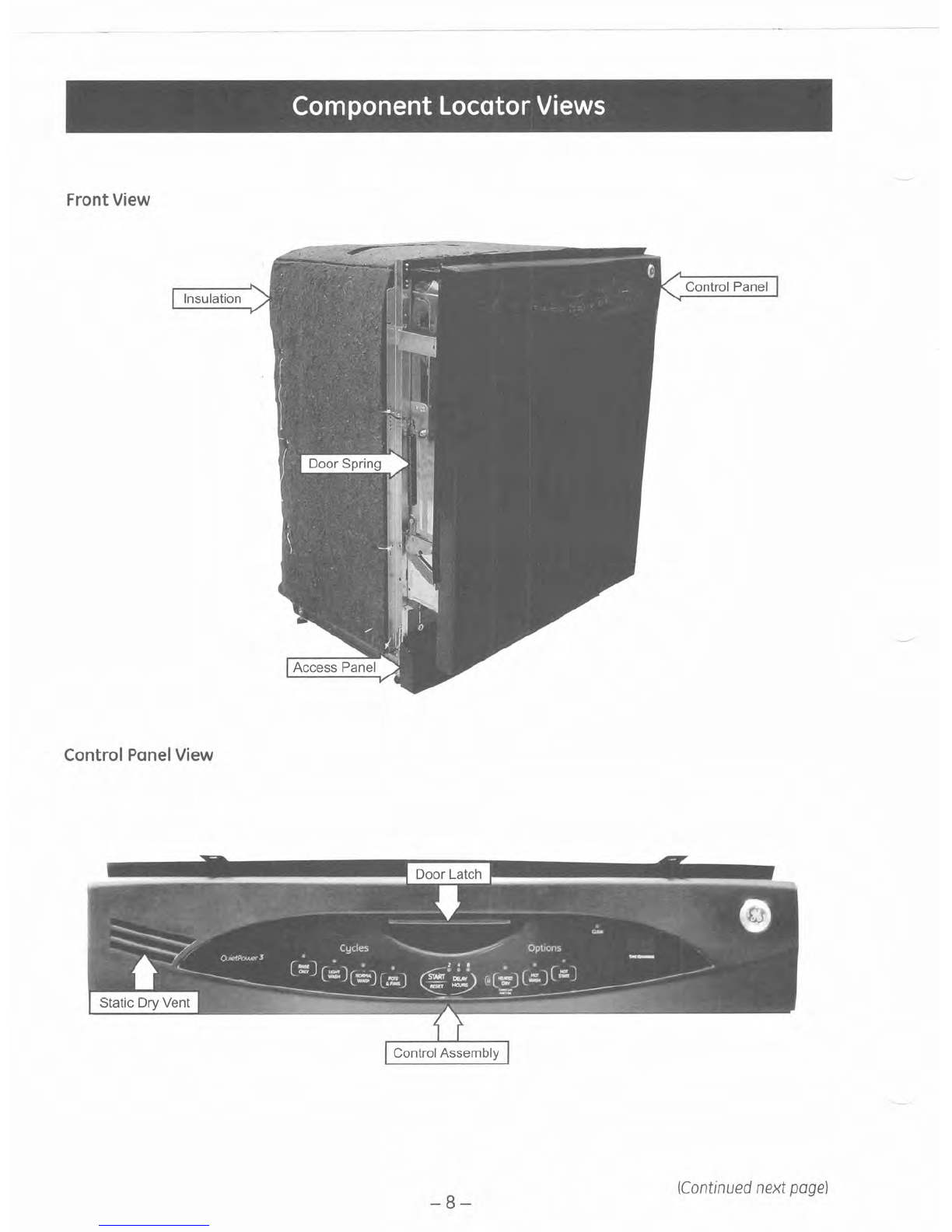
Component LocatorViews
..........................................................................................................................................
8
Control Assembly
..............................................................................................................................................................
12
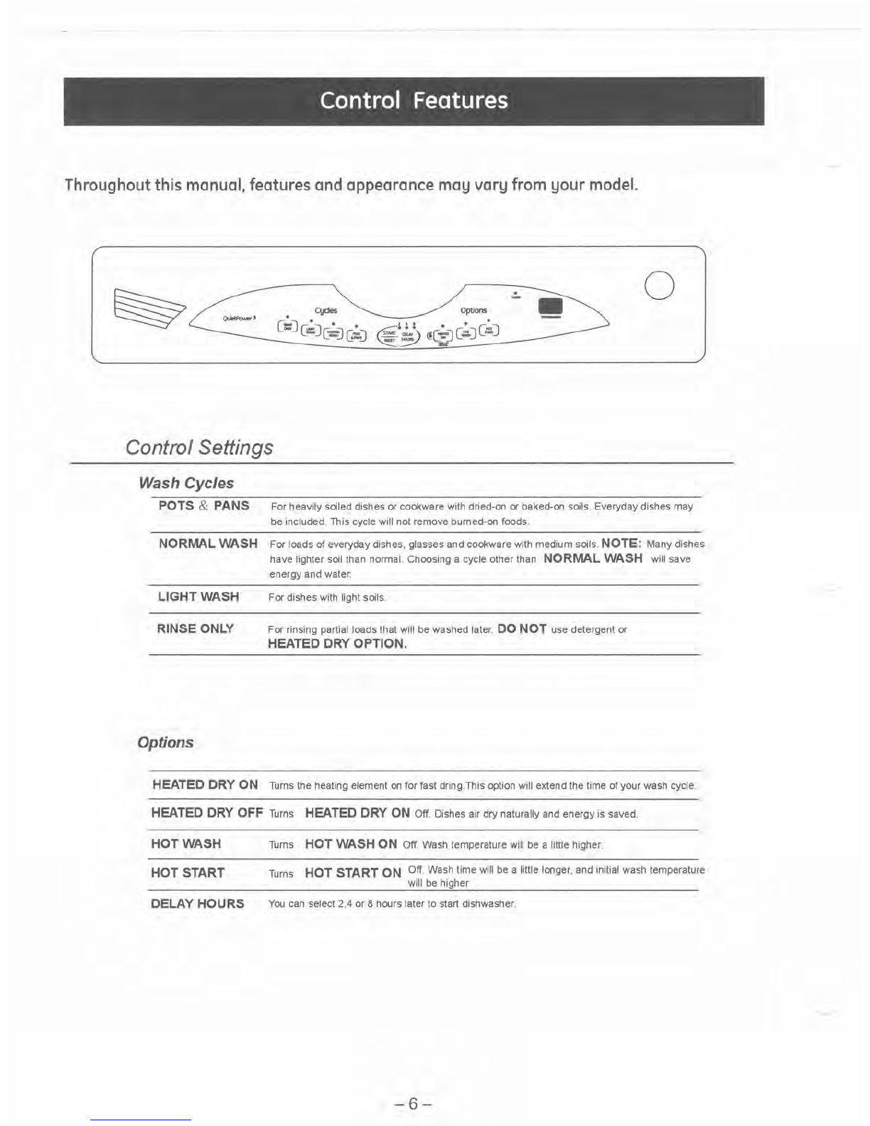
Control Features
...............................................................................................................................................................
6
Control Panel
......................................................................................................................................................................
11
~etergent/RinseModule
................................................................................................................................................
16
Diagnostics andService Information
......................................................................................................................
28
Dishwasher Components
..............................................................................................................................................
11
Door Assembly
................................................................................................................................................................
17
...........................................................................................................................
Door Latch and ReleaseAssembly 13
Door Panel
............................................................................................................................................................................
11
Door Switch Assembly
...................................................................................................................................................
15
Drain PumpAssembly
....................................................................................................................................................
24
Fill Funnel
.............................................................................................................................................................................
21
Heating Element
................................................................................................................................................................
19
Introduction
........................................................................................................................................................................
5
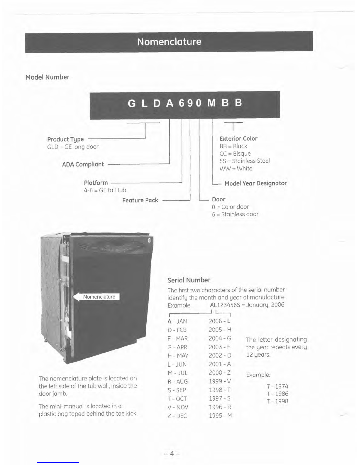
Nomenclature
...................................................................................................................................................................
4
PressureSwitch
.................................................................................................................................................................
23
Schematics andWiring Diagrams
............................................................................................................................
30
Service Test Mode
.............................................................................................................................................................
28
Specifications
.....................................................................................................................................................................
28
Static Dry System
.............................................................................................................................................................
12
Sump Assembly
.................................................................................................................................................................
27
Thermistor
............................................................................................................................................................................
26
...............................................................................................................................................................
Troubleshooting 29
Tub Seal
................................................................................................................................................................................
18
Warranty
..............................................................................................................................................................................
31
Wash Pump Assembly
..................................................................................................................................................
25
Water InletValve
..............................................................................................................................................................
22