– 3 –
Table of Contents
Capacitive Touch Glass .................................................................................................................................................19
Component Locator Views...........................................................................................................................................10
Control Features................................................................................................................................................................ 6
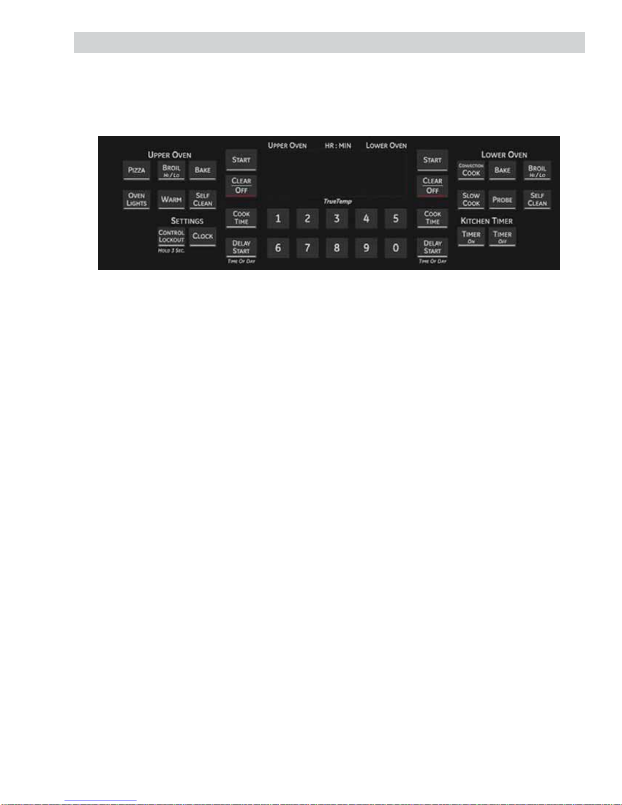
Control Panel .....................................................................................................................................................................19
Control Panel Assembly.................................................................................................................................................19
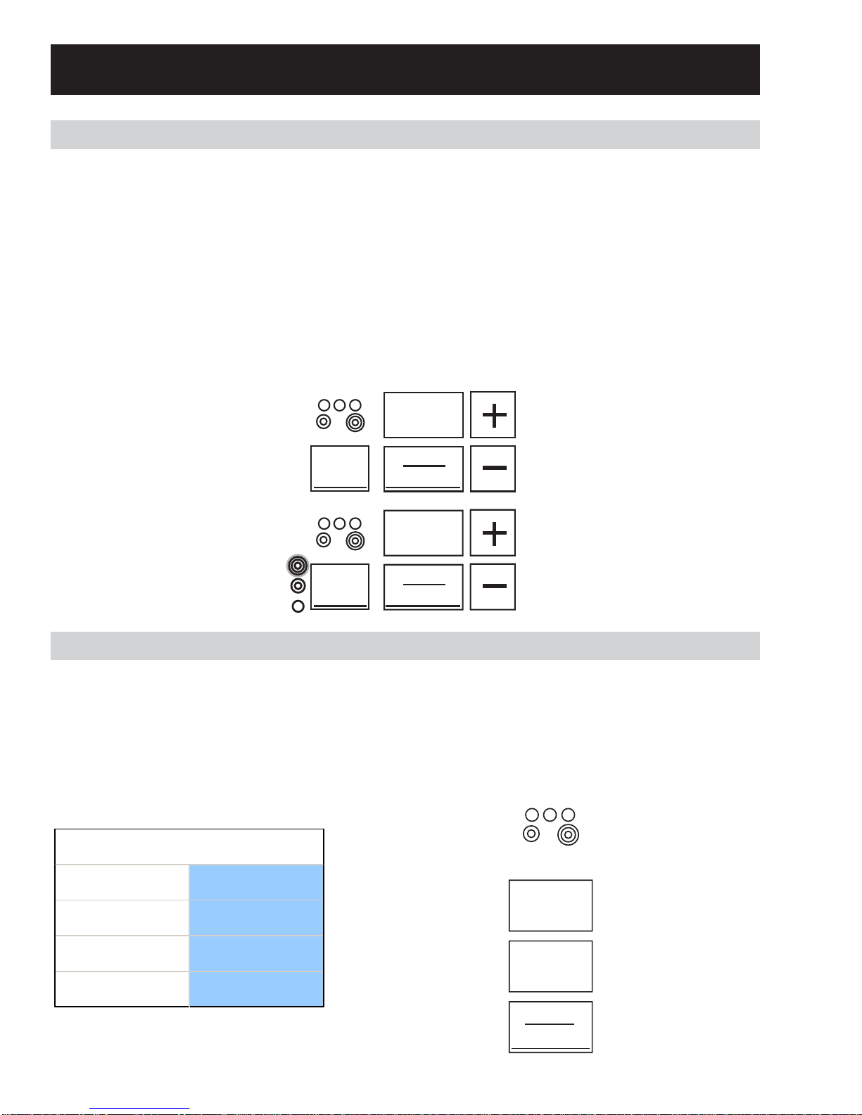
Cooktop Burner Controls............................................................................................................................................... 6
Daughter Relay Board (DRM) .....................................................................................................................................17
Diagnostics and Service Information......................................................................................................................22
Electrical Installation....................................................................................................................................................... 9
Griddle Burner Control.................................................................................................................................................... 7
Hidden Bake Element ....................................................................................................................................................18
Installation........................................................................................................................................................................... 8
Introduction......................................................................................................................................................................... 4
Key Panel Test....................................................................................................................................................................24
LIN Test..................................................................................................................................................................................24
Main Logic Board .............................................................................................................................................................20
Main Logic Board Failure Codes................................................................................................................................22
Nomenclature.................................................................................................................................................................... 5
Oven Components ..........................................................................................................................................................16
Oven Sensors......................................................................................................................................................................25
Rear Cover Removal .......................................................................................................................................................16
Relay Boards Connector Locator Views.................................................................................................................13
Relay Board Voltages......................................................................................................................................................25
RPSM Aux Board ...............................................................................................................................................................17
RPSM Main Board ............................................................................................................................................................16
Sales/Demo Mode............................................................................................................................................................ 8
Schematics and Wiring Diagrams............................................................................................................................26
Self Clean.............................................................................................................................................................................. 7
Test Mode.............................................................................................................................................................................24
Thermal Cutout (TCO) .....................................................................................................................................................17
Warming Zone Control................................................................................................................................................... 6
Warranty..............................................................................................................................................................................29