GE Consumer & Industrial ZIC360NR How to use

PUB # 31-9122 6/04
MODEL SERIES:
ZIC360NR
ZICS360NR
TECHNICALSERVICE GUIDE
Monogram Bottom Mount Inverter
Compressor Refrigerators with
Electronic Controls
GE Consumer & Industrial

– 2 –
IMPORTANT SAFETY NOTICE
The information in this service guide is intended for use by
individuals possessing adequate backgrounds of electrical,
electronic, and mechanical experience. Any attempt to repair a
major appliance may result in personal injury and property
damage. The manufacturer or seller cannot be responsible for the
interpretation of this information, nor can it assume any liability in
connection with its use.
WARNING
To avoid personal injury, disconnect power before servicing this
product. If electrical power is required for diagnosis or test
purposes, disconnect the power immediately after performing the
necessary checks.
RECONNECT ALL GROUNDING DEVICES
If grounding wires, screws, straps, clips, nuts, or washers used to
complete a path to ground are removed for service, they must be
returned to their original position and properly fastened.
GE Consumer & Industrial
Technical Service Guide
Copyright © 2004
All rights reserved. This service guide may not be reproduced in whole or in part
inanyformwithoutwrittenpermissionfromtheGeneralElectricCompany.

– 3 –
TABLE OF CONTENTS
TECHNICALDATA .................................................................................................................... 5
MODELNOMENCLATURE ........................................................................................................ 6
MINI-MANUAL .......................................................................................................................... 6
RATING PLATE........................................................................................................................ 6
COMPONENTANDCONNECTOR LOCATORVIEWS .............................................................. 7
CABINET................................................................................................................................... 8
Cabinet............................................................................................................................... 8
Machine Compartment ..................................................................................................... 8
Door Closure Mechanism.................................................................................................. 9
Fresh Food Door and Hinges.......................................................................................... 10
Door .................................................................................................................................. 10
Freezer Drawer ............................................................................................................... 10
Door and Drawer Gaskets.............................................................................................. 10
Rollers and Leveling........................................................................................................11
ICEMAKER...............................................................................................................................11
Water Valve and Water Line ...........................................................................................11
AIRFLOW ............................................................................................................................... 13
Damper ............................................................................................................................ 13
Evaporator Fan ................................................................................................................ 14
Condenser Fan ................................................................................................................ 17
Drain Pan Fan ................................................................................................................. 18
DEFROSTSYSTEM ................................................................................................................ 18
Adaptive Defrost .............................................................................................................. 18
Defrost Heater ..................................................................................................................20
Evaporator Thermistor .................................................................................................... 20
Defrost Overtemperature Thermostat ............................................................................ 20
CONTROLSYSTEM ............................................................................................................... 21
Touch Panel and Temperature Control Board.............................................................. 21
Main Control Board ......................................................................................................... 22
Main Control Board Locator Tables ............................................................................... 26
Thermistors ...................................................................................................................... 28
ELECTRICALSYSTEM ........................................................................................................... 29
Door and Drawer Switches............................................................................................. 29
Master Light Switch ........................................................................................................ 29
Temperature Overload Device (TOD)............................................................................. 29
Schematic ........................................................................................................................ 30
REFRIGERATION SYSTEM............................................................................................... 31
Inverter Compressor........................................................................................................ 33

– 4 –
Inverter............................................................................................................................. 35
Condenser........................................................................................................................ 37
Condenser Loop .............................................................................................................. 37
Drier.................................................................................................................................. 38
Evaporator ....................................................................................................................... 38
Auxiliary Line ..................................................................................................................39
Refrigerant Charge ......................................................................................................... 39
DIAGNOSTICMODE............................................................................................................... 40
ILLUSTRATED PARTS ........................................................................................................... 41
WARRANTY ............................................................................................................................ 51
Table of Contents (cont.)

– 5 –
TECHNICAL DATA
TemperatureControl...........................WR55X10098
Lamp Overtemperature Thermostat..WR50X10003
Defrost Heater Overtemperature
Thermostat.............WR50X10030
DefrostHeater....................................WR51X10015
CondenserFan Motor.........................WR60X10053
CondenserFan Blade........................WR60X10049
EvaporatorFan Motor.........................WR60X10043
EvaporatorFan Blade.........................WR60X10050
MainBoard..........................................WR55X10433
Thermistors (2-FF, 1-FZ, 1-EV)..........WR55X10028
DrainPan FanMotor...........................WR60X10106
Damper...............................................WR09X10065
Evaporator...........................................WR85X10007
Compressor........................................WR87X10064
Condenser..........................................WR84X10030
Dryer.....................................................WR86X0096
Inverter................................................WR55X10155
DISCONNECT POWER CORD BEFORE SERVICING
IMPORTANT - RECONNECT ALL GROUNDING DEVICES
All parts of this appliance capable of conducting
electrical current are grounded. If grounding wires,
screws, straps, clips, nuts or washers used to
complete a path to ground are removed for service,
they must be returned to their original position and
properly fastened.
CAUTION
To avoid personal injury when servicing the
condensing unit, stand on a ladder which will give
enough support to allow removal of the top panel
and safely allow access to service the unit.
Max Defrost Control
W/No Door Openings ..................... 60 hrs @ 40 min
Evap Defrost Thermo Disc ............................... 65-45°F
Light Thermostat. .......................................... 190-130°F
Electrical Rating: 115V AC 60 Hz ..................... 9.0 amp
Maximum Current Leakage............................. 0.75 mA
Maximum Ground Path Resistance .......... 0.14 Ohms
Energy Consumption .......................... 39 KWhr/month
ELECTRICAL SPECIFICATIONS
NO LOAD PERFORMANCE
CONTROL POSITION 37-0°F and
AMBIENT TEMPERATURE OF
70°F90°F
Fresh Food, °F .............................. 35-39 ............... 35-39
Frozen Food, °F .......................... (-4) +4 ............. (-4) +4
Percent Running Time ...................... 60 .................... 80
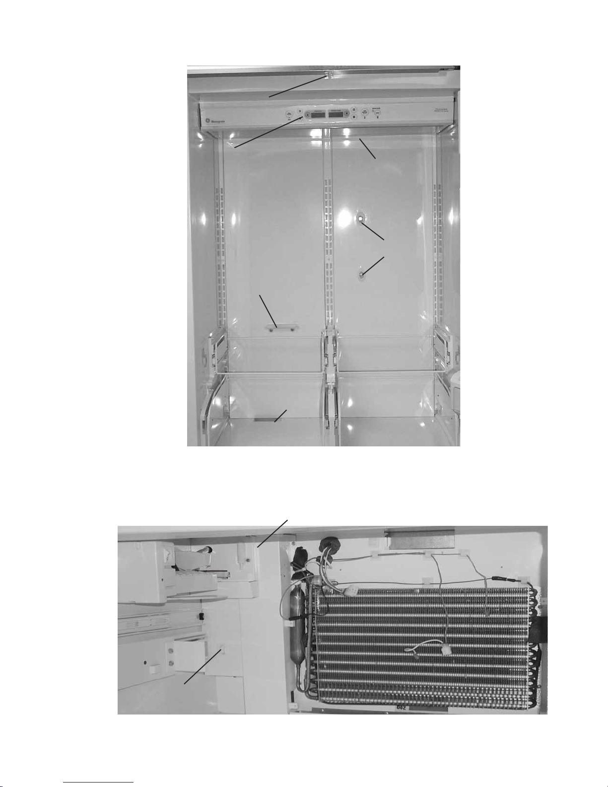
REFRIGERATION DIAGNOSIS
To access the low pressure side of the system, install a
WJ56X61 valve only on the process tube extending
from the compressor case.
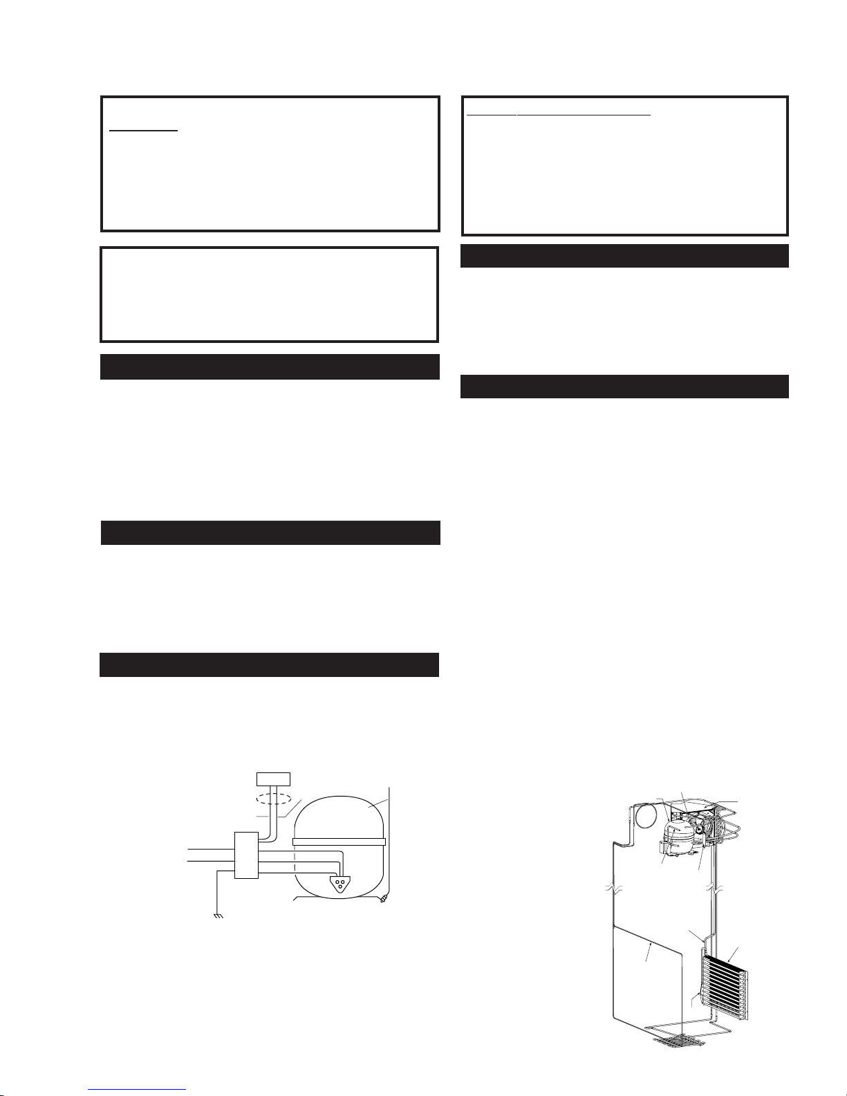
COMPRESSOR
GREEN/YELLOW
GREEN/YELLOW
BLACK
ORANGE
GROUND
TO CABINET
WIRING
COMMUNICATION
SIGNAL
RED
WHITE
GROUND
INVERTER
BLACK
BLUE
BROWN
IMPORTANT SAFETY NOTICE
This information is intended for use by individuals
possessing adequate backgrounds of electrical,
electronic and mechanical experience. Any attempt
to repair a major appliance may result in personal
injury and property damage. The manufacturer or
seller cannot be responsible for the interpretation
of this information, nor can it assume any liability
in connection with its use.
REPLACEMENT PARTS
Compressor ................................................. 833 BTU/hr
Minimum Compressor Capacity
Vacuum, ..................................................... 22 inches
Minimum Equalized Pressure
@ 70°F..................................................... 60/65 PSIG
@ 90°F..................................................... 79/80 PSIG
R134a Refrig. Chg. ........................................... 13.00 oz
REFRIGERATION SYSTEM
Sealed System
CONDENSER
COMPRESSOR
INVERTER*
PROCESS TUBE DRYER
SUCTION TUBE
EVAPORATOR
CONDENSER LOOP
CAPILLARY
*Approximate
location of
inverter

– 6 –
MODEL NOMENCLATURE
Brand/Product
Z-Monogram
Style
I - Built In
Configuration
C - Bottom Mount
Color
S - Stainless
Blank-TrimModel
Size
360 - 36 Inches Wide
Engineering
A-InitialDesign
B - 1st Revision
C-2ndRevision
D-3rdRevision
Etc.
Door Type
F - Flat
RH-RightDoorSwing
LH-LeftDoorSwing
Icemaker/Exterior
N-NonDispenser
Model Year
R-2004Energy
ZICS360 NRA LH
Serial Number
The first two numbers of the serial number
identify the month and year of manufacture.
Example: AG123456S = January, 2004
A
- JAN 2005 - H
D - FEB 2004 -
G
F - MAR 2003 - F
G - APR 2002 - D
H - MAY 2001 - A
L - JUN 2000 - Z
M - JUL 1999 -V
R - AUG 1998 -T
S - SEP 1997 - S
T - OCT 1996 - R
V - NOV 1995 - M
Z - DEC 1994 - L
The letter designating
the year repeats every
12 years.
Example:
T - 1974
T - 1986
T - 1998
MINI-MANUAL
The mini-manual is located behind the
grille panel at the top of the unit. It is taped
to the left side wall of the machine
compartment. When done, return the
mini-manual to its original location for
future use.
RATING PLATE
The rating plate, located inside the
fresh food compartment under the
right-hand storage drawer, contains
the model and serial numbers.
Additionally,therating platespecifies
the minimum installation clearances,
electrical voltage, frequency,
maximum amperage rating,
refrigerant charge, and type.

– 7 –
FreshFoodCompartment
P000337
6
Freezer Drawer Switch
Icemaker
Freezer Thermistor
Freezer Compartment
P0003329
Fresh Food
Thermistors
Temperature Touch Panel
Door Switch
Damper
Air Duct
ColdAir
Outlets
COMPONENT AND CONNECTOR LOCATOR VIEWS

– 8 –
Bolts Track Bolt
Right Side of Machine Compartment
Bolt
Track Bolt Screws
Left Side of Machine Compartment
Raise
Grille
Panel
to Stop
Position
Remove 2 Screws
Each Side to
CABINET
Cabinet
The outer case is made of galvanized steel. The
fresh food and freezer liners are painted metal with
a smooth finish. Individual fresh food and freezer
compartments provide separation and enhanced
individual control between the compartments. The
metal liner provides a thermal break between the
interior of the refrigerator and freezer
compartments and reduces the transfer of heat
from the room into the fresh food and freezer
compartments. The liner is not removable or
replaceable.
Machine Compartment
The machine compartment is located on the top of
the unit and has a movable chassis that can be
extended from the front of the unit to provide
access to the refrigeration system and
components.
Caution: Avoidkinking therefrigeration lineswhen
sliding the chassis out and back in.
To extend the chassis:
1. Raise the grille panel to stop position.
2. Remove the wire guard and door cover.
3. Remove the door switch.
4. Disconnect the door closure mechanism
spring from the pin and remove the pin by
turning it counterclockwise.
5. Remove the 2 screws securing the inverter.
6. Remove the door spring.
7. Remove the 2 front (7/16-in.) bolts from tray.
8. Loosen the 2 rear (7/16-in.) tray bolts.
9. Pull the chassis forward until it reaches the
stops in the tracks, working the refrigeration
tubing as you pull the chassis out.
Note. When sliding the chassis back into position,
be certain the lines and wiring have not fallen
behind the chassis.

– 9 –
Spring
AllenHead Bolt
Bolts
ActuatorArm
Door Closure Mechanism
The door closure mechanism uses a spring to
provide positive door closure from 30 degrees.
The door closure mechanism actuator arm has a
spring attached to the rear and is supported by
guide rollers on either side of the base channel.
The roller circumferences and the actuator arm
detents are matched for smooth operation. The
arm is attached to the door with an Allen head
shoulder bolt.
The closure mechanism allows easy opening to
approximately 90 degrees, where the arm has a
detent to permit the door to remain open at 90
degrees with minimal tension. Once the door is
opened beyond 90 degrees, the closure
mechanism pulls the door open until the closure
arm engages the door stop at approximately 130
degrees. The reverse action occurs when the door
is closed.
Note: The door closure mechanism and the top
door hinge are held by the same bolts. Take the
necessary precautions to secure the fresh food
door when the door closure mechanism is being
removed.
• The actuator arm is spring loaded with moderate
spring tension.
To remove the door closure mechanism
1. Remove the 3/16-in.Allen head bolt and
spacer from the door and actuator arm.
2. Disconnect the spring from the pin on the top
of the cabinet and pull the actuator arm from
the closure mechanism.
3. Remove 4 (3/8-in.) bolts and the door closure
mechanism.
Shown with Inverter Removed for Clarity

– 10 –
P0003336
CenterHinge
Screws
Screws
Slide/Support
Assembly
Door
Left Side of Freezer Door
Fresh Food Door and Hinges
WARNING: Use the appropriate safety equipment
and lifting techniques.
Caution: Use wood or a heavy plastic sheet to
protect the floor where the door will be placed.
Note: Unit must be removed from its installation
to remove center hinge.
Door
The door is of one-piece construction with foam
insulation. One-piece construction provides
superior thermal performance and reduces air
infiltration.
The inner door panel and outer door panel cannot
be separated and must be replaced as an
assembly.
1. Remove all food and bins from the inner door
liner.
2. Tape door to cabinet.
3. Remove the door closure mechanism (see
previous procedure).
4. Remove the upper hinge.
5. Remove tape and lift the door off center hinge.
6. Remove 4 T-27 Torx screws and center hinge.
Freezer Drawer
1. Loosen 4 screws connecting each side of the
freezer door to the slide/support assemblies.
2. Lift door up and out to remove.
Door and Drawer Gaskets
The fresh food door and freezer drawer have
magnetic gaskets that create a positive seal to the
front of the steel cabinet. The magnetic door
gaskets are secured to the fresh food door and
freezer drawer by a barbed edge that locks into a
retainerchannel.
1. Starting at any corner, pull the old gasket out of
the retainer channel.
2. Soak the new gasket in warm water to make it
pliable.
3. Push the barbed edge of the gasket into the
retainerchannel.

– 11 –
Icemaker
Feeler Arm
Power Switch
Green
Power Light
Hex Nut
Wheel
Leveling Leg
P0003393
WaterValve
Water Filter Bracket
Rollers and Leveling
This model has 4-point leveling provided by
adjustable rollers on the rear and leveling legs on
the front. It also has 2 nonadjustable front rollers
that are used only for unit positioning.
To level the unit:
1. Turn the 7/16-in. hex nut located above the
front rollers to adjust the roller on the rear of
the unit. Turn clockwise to raise,
counterclockwise to lower.
2. Turn the front legs with a 1-1/4 in. open end
wrench to adjust the front of the unit. Turn
clockwise to raise, counterclockwise to lower.
ICEMAKER
The icemaker is mounted to the upper left wall of
the freezer cabinet. Under normal operating
conditions, temperatures, door openings, and food
load, the icemaker is capable of producing
approximately 100 to 130 cubes in a 24-hour
period.
Note: The freezer door light switch, located on
the back wall of the freezer, also serves as an
icemaker interlock (or kill) switch. It will open the
circuit to the icemaker any time the freezer drawer
is open.
To service the icemaker, refer to GE Publication
31-9063.
Water Valve and Water Line
The water valve is mounted to the side of the
water filter bracket in the machine compartment.
A plastic water line is routed from under the unit,
up the back of the cabinet, into the machine
compartment, and to the water valve.
A low-pressure plastic water line supplies water to
the icemaker from the water valve. The plastic
water line is routed from the water valve, out the
back of the machine compartment, down the back
of the cabinet to the fill tube grommet. The
icemaker fill tube is also plastic.
To Replace the Water Valve
Note: Some water may leak from the water supply
line and valve when they are disconnected.
1. Shut off the water supply to the freezer.

– 12 –
P0003413
P
Screw
WaterValve
Access Cover
2. Raise the machine compartment cover panel.
3. Remove 2 Phillips screw attaching the water
valvecover.
4. Remove 2 Phillips screw attaching the water
valve to the filter bracket.
5. Disconnect the wiring harness connector and
2 water lines from the water valve and remove.
To Replace the Water Line from the Water Valve to
the Fill Tube Grommet
Note: Some water may leak from the water supply
line and valve when they are disconnected.
1. Shut off the water supply to the freezer.
2. Remove the unit from its installation.
3. Remove 14 (1/4-in.) screws and the metal
access cover.
4. Disconnect the water line at the quick
connector by pushing in the white collar on the
quick connector while pulling the water line out.
5. Loosen the clamp at the fill tube grommet and
remove the water line.

– 13 –
P0003387
Screws
Screws
LightAssembly
P0003380
Screws
Damper
AIRFLOW
Damper
The fresh food compartment receives chilled air via an electronic damper that is positioned at the top
rear of the fresh food compartment. The damper is controlled by the main control board and when
open, allows the evaporator fan to push chilled air from the evaporator into the fresh food compartment.
To remove the damper
1. Remove the light cover.
2. Remove 8 Phillips screws and the light
assembly.
3. Disconnect the damper wiring.
4. Remove 2 Phillips screws and the damper.

– 14 –
The evaporator fan is the same fan used on previous models; however a significant difference is that the
main control board does not require, nor receive, input from the fan feedback/rpm (blue) wire. The fan
utilizes a permanent magnet, 4-pole, DC motor that operates at three different speeds: high, medium,
and low. The speed of the fan is controlled by the voltage output from the main control board. Voltage
output from the control board to the fan is 13.2 VDC; however to regulate the speed of the fan, the main
control board uses pulse width modulation (PWM). When operating, voltage is sent in pulses (much like
a duty cycle) as opposed to an uninterrupted flow. This pulsing of 13.2 VDC produces effective voltage
being received at the motor, which is the equivalent to a reduction in voltage. Fan speed will be selected
and maintained by the main control board regulating the length and frequency of the 13.2 VDC pulse.
Temperature may cause some fan speed variation. Fan speed may vary +/- 5%, depending on the
temperature, with higher temperatures causing slightly higher speeds.
Evaporator Fan
The position of the fan blade in relation to the shroud is important. Refer to illustration for specifications.
5/16 +/- .03
Airflow
High Speed (12 VDC measured)
Medium Speed (9.2 VDC measured)
Low Speed (8 VDC measured)
EVAPORATOR FAN SPEEDS
12 VDC
9.2 VDC
8 VDC
13.2 VDC
0 VDC
0 VDC
0 VDC
13.2 VDC
13.2 VDC

– 15 –
Evaporator and Condenser Fan Resistors
If the fan shorts, it will damage the main control
board. If the resistor on the main control board is
burnt, you must replace the fan and the board (see
photo).
1
5
1
10
1
9
J1 or J14
J5
6
J3 or J10
J2 or J13
1
DEFROST
K4
21
J6
K5
CUSTOM COOL
K7
PAN
HEATER
CRUSHER
K2
WATER
K3
J4 or J16
1
8
J7
AUGER
K1
1
J2
EARTH
EARTH
J1
J18
J12
J15
1
J19
J11
J9
Comm. 2-Way Digital
Comm. +12V
Comm. Common
Damper - Blue
Damper - White
Damper - Red
Damper - Yellow
FF1 Thermistor
FF2 Thermistor
FZ Thermistor
Evaporator Thermistor
+5V
Custom Cool Damper1 +
Custom Cool Damper1 -
+5V
Custom Cool Thermistor
Evaporator Fan Tach.
Fan Common
Evaporator Fan
Condenser Fan
Custom Cool Fan
Fan +12V
Inverter Common
Inverter Output
Drain Pan Heater
Not Used
Defrost Heater
Line (L1)
Neutral
FZ Door Switch
FF Door Switch
Custom Cool Heater
Auger Motor Interlock
Water Valve
Crusher Solenoid
Auger Motor
J8
Not Used
Evaporator Fan Resistor
Condenser Fan Resistor

– 16 –
White Wire (DC Common)
The white wire is the DC common wire used for
testing. During repairs, DC polarity must be
observed. Reversing the DC polarity will cause a
shorted motor and/or board.
Red Wire (Supply)
Each motor uses an internal electronic controller
to operate the motor. Supply voltage from the
main control board remains at a constant
12 VDC.
Blue Wire (Feedback/RPM)
The blue wire feeds rpm (speed) information to
the main control board, allowing the board to
maintain consistent fan speeds. Loss of feedback
from the blue wire will result in the fan accelerating
to maximum speed. Measure the fan rpm using
the frequency between the blue and white wires.
High speed - 205 to 215 Hz (3140 RPM)
Medium speed - 155 to 165 Hz (2415 RPM)
Low speed - 140 to 150 Hz (2160 RPM)
Yellow Wire (Signal)
The yellow wire is the input wire from the main
control board. The main control board provides
8 VDC effective voltage for low speed, 9.2 VDC
effective voltage for medium speed, and 12 VDC
for high speed. The fan will operate in low speed
only when the fresh food thermistor is satisfied.
Note: When testing these motors:
• You cannot test with an ohmmeter.
• DC common is not AC common.
• Verify 2 voltage potentials:
a. Red to white - power for internal controller.
b. Yellow to white - power for fan.
• Observe circuit polarity.
• Motors can be run for short periods using a
9-volt battery. Connect the white wire to the
negative (-) battery terminal only. Connect the
red and yellow wires to the positive (+) battery
terminal.
Some of the low voltage DC
connector labeling on this model
may differ from other models. The
function and diagnostics for these
connectors are identical for all
models.
1
5
1
10
1
9
J1 or J14
J5
6
J3 or J10
J2 or J13
1
DEFROST
K4
21
J6
K5
CUSTOM COOL
K7
PAN
HEATER
CRUSHER
K2
WATER
K3
J4 or J16
1
8
J7
AUGER
K1
1
J2
EARTH
EARTH
J1
J18
J12
J15
1
J19
J11
J9
Comm. 2-Way Digital
Comm. +12V
Comm. Common
Damper - Blue
Damper - White
Damper - Red
Damper - Yellow
FF1 Thermistor
FF2 Thermistor
FZ Thermistor
Evaporator Thermistor
+5V
Custom Cool Damper1 +
Custom Cool Damper1 -
+5V
Custom Cool Thermistor
Evaporator Fan Tach.
Fan Common
Evaporator Fan
Condenser Fan
Custom Cool Fan
Fan +12V
Inverter Common
Inverter Output
Drain Pan Heater
Not Used
Defrost Heater
Line (L1)
Neutral
FZ Door Switch
FF Door Switch
Custom Cool Heater
Auger Motor Interlock
Water Valve
Crusher Solenoid
Auger Motor
J8
Not Used
J4 or J16 J3 or J10 J1 or J14
J2 OR J13

– 17 –
Screws
Wiring Harness Connector
Housing
Fan
Motor
0.375"
1/2"
Air Flow
0.50" ± 0.05
Bracket
GEA01148
Condenser Fan Adjustment
+/-.100
Airflow
P0003374
Screws
Insulation
To remove the fan
1. Remove the drawer (see procedure).
2. Remove 5 screws securing the rear duct.
3. Disconnect the freezer light and light thermostat
wiring and the remove duct.
4. Disconnect the wire connector from the fan motor.
5. Remove 2 screws from the fan motor bracket and
remove the evaporator fan motor.
Condenser Fan
The condenser fan is a permanent-magnet, 4-pole,
DC motor that will operate at 3 speeds. Fan speed
(low, medium, high) corresponds with compressor
speed to minimize pressure variations in the sealed
system. The speed of the fan is controlled by the
voltage output from the main control board. Voltage
output from the control board to the fan is 13.2 VDC;
however to regulate the speed of the fan, the main
control board uses pulse width modulation (PWM).
Inlet air is available through the left front and left rear of
the machine compartment.
If the fan shorts, it will damage the main control board.
If the resistor on the main control board is burnt, you
must replace the fan and the board.
The condenser fan is mounted with screws to a fan
shroud and mounting bracket in back of the
condenser.
To remove the fan
1. Extend the machine compartment chassis (see
Machine Compartment).
2. Disconnect the condenser fan wiring at the
harness connector.
3. Remove 4 screws and fan assembly.
4. Remove fan blade, 2 screws from the fan
mounting bracket, and fan motor.
Note: A magnetic tip screwdriver may be required to
install the condenser fan mounting screws.
To install lower fan mounting screw:
1. Pull back foam insulation to visually locate screw
hole.
2. Locate hole with fingers of left hand.
3. Place screw on the tip of the screwdriver.
4. Use your right hand to maneuver the screwdriver
and use your left hand to guide the screw into the
hole.

– 18 –
Drain Pan Fan
The Monogram Bottom Mount has an auxiliary
evaporation fan located under the unit. The
purpose of this fan is to improve the evaporation
rate of drain water should extreme conditions
occur.
Should this fan malfunction, there is no
replacement procedure. The absence of this fan
will not affect drain water evaporation under
normal conditions. Astainless steel hot gas loop
routed through the drain pan will provide ample
evaporation.
To remove the fan
1. Remove toe kick (2 screws).
2. Slide out and remove drain pan.
3. Disconnect harness from fan motor.
4. Remove fan by unscrewing 2 screws
accessible from within the pan housing.
DEFROST SYSTEM
Adaptive Defrost
Adaptive Defrost can be described as a defrost
system that adapts to a refrigerator’s surrounding
environment and household usage.
Unlike conventional defrost systems that use
electromechanical timers with a fixed defrost cycle
time,Adaptive Defrost utilizes an intelligent,
electronic control to determine when the defrost
cycle is necessary. In order to accomplish the
correct defrost cycle time, the main control board
monitors the following refrigerator operations:
•Length of time the refrigerator doors were open
since the last defrost cycle
• Length of time the compressor has run since
the last defrost cycle
• Amount of time the defrost heaters were on in
the last defrost cycle
Adaptive Defrost is divided into 4 separate cycles.
Those operations are:
•CoolingOperation
• Pre-Chill Operation
• Defrost Heater Operation
• Dwell Period

– 19 –
Adaptive Defrost (Cooling Operation)
During the cooling operation, the main control
board monitors door opening (fresh food door and
freezer drawer) and compressor run times. The
board counts the time the doors are open. It
reduces the length of time between defrosts by
300 seconds (multiplication factor) for each
second that each door is open (if both doors are
open, it reduces it by twice the amount). The
multiplication factor reduces compressor run time.
If the doors are not opened, the compressor will
run up to 60 hours between defrosts. If the doors
are opened frequently and/or for long periods of
time, the compressor run time between defrosts
will be reduced to as little as 8 hours.
Adaptive Defrost (Pre-Chill Operation)
When the main control board determines that
defrost is necessary, it will force the refrigerator
into a continuous cool mode (pre-chill). During pre-
chill, the freezer temperature may be driven below
the set point. However, the fresh food temperature
will be regulated by the evaporator fan running at
low speed. Pre-chill will last for 30 minutes. These
models do have an 8-hour defrost hold-off.
Adaptive Defrost (Defrost Heater Operation)
After 30 minutes of pre-chill operation, the main
control board turns off the compressor, condenser
fan, and evaporator fan.
During defrost operation, the main control board
monitors the evaporator temperature using
evaporator thermistor inputs. Typically, the
evaporator thermistor will sense a temperature of
45°F within 16 minutes. When the thermistor
senses 45°F, the main control board will terminate
defrost heater operation. Maximum defrost cycle
(heater on) time is 35 minutes (main control board
time out).
The defrost system is protected by a defrost
overtemperature thermodisc (bimetal switch). The
thermostat opens when the evaporator
temperature raises to 60°F and closes when the
evaporator temperature lowers to 45°F.
Adaptive Defrost (Dwell Period)
After defrost heater operation has been terminated
by the main control board, a 20-minute dwell
period occurs. During this period, the
compressor, condenser fan, and evaporator fan
remain off. The remaining frost melting from the
evaporator will continue to drip and drain so that,
prior to the cooling operation, the evaporator will be
totally clear of any moisture. The pan heater is on
for the entire 20 minute dwell period.
Normal Operating Characteristics
• The fill tube heater is on when the defrost
heaters are on.
• Pan heaters are on when the defrost heaters
are on and during dwell period (25 minutes
plus defrost time).

– 20 –
P0003343
Defrost Heater
Evaporator Thermistor
P0003407
Screws
Screws
Clip
P0003343
Defrost Overtemperature Thermostat
Defrost Heater
Caution: Use care to avoid scratching the finish
on unit walls.
The defrost heater is a single-calrod type, radiant
heater mounted under the evaporator.
To remove the defrost heater:
1. Remove the drawer (see procedure).
2. Remove upper right slide/support assembly by
removing 3 Phillips screws.
3. Remove lower right slide/support assembly by
removing 3 Torx screws.
4. Remove 5 screws, disconnect light and light
thermostat wiring, and remove rear duct.
5. Remove 4 screws and evaporator cover.
6. Disconnect the heater lead wires.
7. Remove the clip securing the heater to the
evaporator and remove the heater.
Evaporator Thermistor
The evaporator thermistor is mounted on the
upper left side of the evaporator. The defrost cycle
will terminate when the main control board detects
45°F from the evaporator thermistor. The main
control board must sense 45°F in less than 40
minutes, or the defrost cycle will time out. Average
time to defrost is 20 minutes. Defrost time should
not exceed 40 minutes. Defrost time does not
include dwell and post dwell periods.
Defrost Overtemperature Thermostat
The defrost overtemperature thermostat (bimetal
switch) is mounted on the evaporator and provides
overtemperature protection during defrost. This
thermostat will open at 65°F and will close
at 45°F.
Note: The main control board will not know if the
heater does not come on due to a broken heater,
open defrost overtemperature thermostat, or open
wiring harness. The defrost heater is controlled by
maximum time on the main control board or
temperature at the evaporator thermistor.
This manual suits for next models
1
Table of contents
Other GE Consumer & Industrial Refrigerator manuals
Popular Refrigerator manuals by other brands

Zanussi
Zanussi ZC 244 AGO Instruction book

Dometic
Dometic REFRIGERATION 10-Series Short Operating Manual

Kenmore
Kenmore 7531 - 22.0 cu. Ft. Top Freezer Refrigerator Use & care guide

Beko
Beko TLG 980 operating instructions

CSI
CSI BRUTE Series User manual and product specifications

Fulgor Milano
Fulgor Milano FBC 343 T NF ED Instructions for installation and use