GE Lighting IMMERSION RV40 Series User manual

imagination at work
IMME SION™
LED Refrigerated Display Lighting
Center Mullion LED Lights
750 mm (30-inch): GELT403050CTR-SY/-SB (79777/79780), GELT403040CTR-SY/-SB (79783/79786)
900 mm (36-inch): GELT403650CTR-SY/-SB (79795/79798), GELT403640CTR-SY/-SB (79801/79804)
Description Code (Single Unit Prod ct N mber / 10-Pack Prod ct N mber)
Vertical Cases
RV40 Series
GE
Lighting
Retrofit Installation Guide
BEFO E YOU BEGIN
Read these instructions completely and carefully.
A. Use this unit only in the manner intended by the manufacturer. If you
have any questions, contact the manufacturer.
B. Before servicing or cleaning unit, switch power off at the service panel
and follow appropriate lock out /tag out safety procedures.
isk of electrical shock. Disconnect power before servicing or installing product.
/ isque de choc électrique. Couper le courant avant de réparer ou installer le produit.
WARNING / AVERTISSMENT
isk of injury. While performing installations described, gloves, safety
glasses or goggles should be worn. / isque de blessure. Lors de l'exécution
des installations décrites, des gants, des lunettes de sécurité ou des lunettes
de protection doivent être portées.
CAUTION / ATTENTION
P EPA E ELECT ICAL WI ING
Electrical Req irements
•
The power supply must be supplied with 100-240 VAC,
50/60 Hz., and connected to an individual properly
grounded
branch circuit, protected by a 15 or 20 ampere
circuit breaker or time delay fuse.
•
Wiring must be 2 wire with ground and rated for
75°C (167°F).
• Do not overload driver, follow installation instructions
for the GEPS4000NCMUL-SY.
• Ensure that all connection points are sealed for damp
location using the appropriate method per the NEC or
local electrical code.
LED D IVE COMPATIBILITY
This system is compatible with the GEPS4000NCMUL-SY
LED Driver. Please refer to the separate LED driver installation
guide for appropriate wiring connections.
FO YOU SAFETY
ead and observe all CAUTIONS and WA NINGS shown
throughout these instructions.
• Installation to be performed by factory trained service personnel only.
•
For use inside a commercial refrigeration case with packaged foods only.
This device complies with part 15 of the FCC Rules. Operation is subject to the
following two conditions: (1) This device may not cause harmful interference, and (2)
this device must accept any interference received, including interference that may
cause undesired operation.
NOTE: This equipment has been tested and found to comply with the limits for a Class A
digital device, pursuant to part 15 of the FCC Rules. These limits are designed to provide
reasonable protection against harmful interference when the equipment is operated in a
commercial environment. This equipment generates, uses, and can radiate radio frequen-
cy energy and, if not installed and used in accordance with the instruction manual, may
cause harmful interference to radio communications. Operation of this equipment in a
residential area is likely to cause harmful interference in which case the user will be
required to correct the interference at his own expense.
This Class [A] RFLD complies with the Canadian standard ICES-003. Ce DEFR de la classe
[A] est conforme à la NMB-003 du Canada.

2
• For retrofit only. If you are an OEM, please refer to the OEM
Installation Guide.
• Refer to manufacturing manual for refrigeration case to
identify lighting control circuits. Ensure that power is switched
off at the service panel for the lighting circuit. If a lighting
power switch is not provided in the refrigeration case, power
removal can be performed at the main breaker panel.
• Locate existing lighting components including ballasts,
lampholders, lamps, and lampguards in the refrigeration
case for removal. Please refer to refrigeration manual for any
questions dealing with component locations.
• Remove lamps, lampholder and lamp guards. Cut the wiring,
making the cut as close to the lampholder as possible. Do not
remove wiring from case as it will be utilized to attach the LED
light. Dispose of components per federal and local regulations.
• Locate ballast within system. The most common location is in
the mullion or the electrical raceway found in the bottom of
the refrigerated case.
• Disconnect ballast input and output connectors. Cut the
ballast connector wires nearest to the connector and remove
connector. Unscrew the mounting screws that attach ballast
and remove ballast. Dispose of ballasts according to federal
and local regulations. LED driver installation will begin at Step
7 and Step 8.
• To install the LED light, first identify the wiring for connection
to the LED driver. After removing the connector from ballast,
leave the existing ballast input and output wires for
reconnection in a later step.
emove Existing Lighting Components
1
Tools Required Components Required
LED light
LED driver
Wire cover
M3.5x1.3x13 (#6-32 x 1/2 inch) screws
Twist lock splice wire connectors
Wire stripper/cutter
Tape measure
Screwdriver
Cordless drill
Hammer
2.8mm (7/64-inch) drill bit
Center punch
4
5
6
7
3
2
1
4
5
3
2
1
1
23
45
567
4
Fluorescent Component Location
Lamp with lamp guards
(behind mullion)
Lamp holders
Ballast
1. Mullion
2. Raceway
3. Overhead door frame
A
B
C
WARNING/AVERTISSEMENT
5LVNRI¿UHRUHOHFWULFVKRFN/XPLQDLUHZLULQJDQGHOHFWULFDOSDUWVPD\EHGDPDJHGZKHQGULOOLQJIRULQVWDOODWLRQRI/('UHWUR¿WNLW&KHFNIRU
HQFORVHGZLULQJDQGFRPSRQHQWV5LVTXHGHIHXRXpOHFWURFXWLRQLes pièces et câbles électriques risquent d’être endommagés lors du perçage
GHVWURXVSRXUO·LQVWDOODWLRQGXOXPLQDLUHj'(/9HXLOOH]YpUL¿HUVLGHVFkEOHVHWFRPSRVDQWHVVHWURXYHQWGHUULqUHODSDURLDYDQWGHSHUFHU
7RSUHYHQWZLULQJGDPDJHRUDEUDVLRQGRQRWH[SRVHZLULQJWRHGJHVRIVKHHWPHWDORURWKHUVKDUSREMHFWV3RXUpYLWHUOHQGRPPDJHPHQWGH
FkEODJHRXODEUDVLRQQHSDVH[SRVHUOHFkEODJHDX[ERUGVGHIHXLOOHVGHPpWDORXGDXWUHVREMHWVWUDQFKDQWV

isk of electrical shock. Only those open holes indicated in the photographs and/or drawings may be made or altered as a result of kit installation. Do not leave
any other open holes in an enclosure of wiring or electric components / isque de choc électrique. Seuls les trous ouverts indiqués dans les photos et / ou les
dessins peuvent être faites ou modifiés à la suite du montage du kit. Ne pas laisser autres trous ouverts dans l'enceinte du câblage électrique ou composants.
WARNING / AVERTISSMENT
3
• Measure the total width of the mullion, and mark a vertical
line half the total width near the top and bottom of the mullion.
•
Prepare for the upper end of the Center LED Light. Mark a
horizontal line a minimum 54 mm (2 1/8-inches) from the top
of the mullion, and another horizontal line 10 mm (3/8-inches)
below this line.
• Prepare for the lower end of the Center LED Light. For
750 mm (30-inch) LED Lights, mark a horizontal line 687 mm
(27 1/32-inches) beneath the first line drawn for the top
Mounting Tab. For
900 mm (36-inch) LED Lights, mark a
horizontal line 836 mm (32 29/32-inches)
beneath the first
line drawn for the top Mounting Tab.
• Point the center punch directly at the intersection of the
horizontal lines and the vertical line (top and bottom)
and
establish a dimple.
• Use power drill and 2.8 mm (7/64-inches) drill bit to drill
holes at the
intersection of the vertical center line and the
horizontal lines.
Prepare for Installation of
Center LED Lights
2
of mullion
Total width
10 mm (3/8")
For 750 mm (30-inch)
LED Lights:
687 mm (27 1/32")
Center
punch
at intersection
and drill a
2.8 mm (7/64")
hole
mullion
Half total
width of
LED Driver wires -
top
For 900 mm (36-inch)
LED Lights:
836 mm (32 29/32")
Install Center LED Lights
3LED Driver
Leads
Center LED Light
Power Leads
Mounting Tab
• Place the Center LED Light against the face of the
mullion
near the two holes drilled at the top.
• Insert a M3.5 x 1.3 x 13 (#6-32 x ½-inch) sheet metal screw
into the top slot of the Mounting Tab on the Center LED Light
and into the first hole that was drilled in the center mullion.
• Use a screwdriver to start threading the screw into the
drilled hole.
• Refer to the manufacturing manual for door frame to ensure
there are no components contained inside the mullion that
could be drilled through. Use a M3.5 x 1.3 x 13 (#6 - 3/4-inch)
self-drilling screw to attach the Center LED Light into one
or two of the additional drill through holes located near the
center of the LED Light.
• Repeat for the second screw, and for the lower end of the
Center LED Light.
• Refer to wiring diagram on page 5. Connect the red and black
output wires from the LED Light to the red and black wires on the
LED Driver using the twist lock splice wire connectors provided.

4
LED Driver
Configuration Options
6-Door Case
5-Door Case 4-Door Case 3-Door Case
2-Door Case
LED
DRIVER
The diagrams below represent wiring
configurations for each LED Driver.
LED
DRIVER
LED
DRIVER LED
DRIVER
isk of injury. Do not overload LED Driver, 60-watts maximum per driver. For 30-inch and 36-inch LED Lights, do not exceed
5 Center LED Lights per LED driver loading limit. (2 End LED Lights is equivalent to 1 Center LED Light). isque de blessure.
Ne pas surcharger le driver LED, 60-watts maximum par driver. Dans le cas des lampes LED de 30"-75 cm et de 36"/90 cm, ne
pas dépasser 5 lampes LED centrales par limite de charge du driver. (2 lampes LED latérales équivalent à 1 lampe LED centrale).
CAUTION / ATTENTION
LED
DRIVER LED
DRIVER
Center LED Lights 54321
End LED Light Sets 11111
LED Drivers 21111
Wire Covers 76543
Parts Needed Per Case
6-Door 5-Door 4-Door 3-Door 2-Door

TERMINAL BLOCK
LED DRIVER
WHITE (NEUTRAL)
BLACK (LINE)
SWITCH
BRBR
B
W
BR
G
RIGHT END LED LIGHT
LEFT END LED LIGHT
A
C
B
D
Occupancy Sensor
Gray Purple
isk of electrical shock. Ensure that all connection points are sealed for damp location using the appropriate method per the NEC or local
electrical code.
isque de choc électrique. S’assurer que les points de raccordements sont scellés pour emplacement humide en employant une
méthode permise par le NEC ou par le code électrique local.
WARNING / AVERTISSMENT
One End Set ( ight and Left) &
One Center LED Light
One End LED Light ( ight or Left) &
One Center LED Light
TERMINAL BLOCK
LED DRIVER
WHITE (NEUTRAL)
BLACK (LINE)
SWITCH
BR BR
BW
BR
G
END (R or L) LED LIGHT
CENTER LED LIGHT
A
C
B
D
Occupancy Sensor
Gray Purple
TERMINAL BLOCK
LED DRIVER
WHITE (NEUTRAL)
BLACK (LINE)
SWITCH
BR
BW
BR
G
CENTER LED LIGHT
A
C
B
BR
LEFT END LED LIGHT
BR
RIGHT END LED LIGHT
D
Occupancy Sensor
Gray Purple
Note: LED Lights are polarity insensitive
TERMINAL BLOCK
LED DRIVER
WHITE (NEUTRAL)
BLACK (LINE)
SWITCH
BR
BW
BR
G
CENTER LED LIGHT
A
C
B
D
Occupancy Sensor
Gray Purple
TERMINAL BLOCK
LED DRIVER
WHITE (NEUTRAL)
BLACK (LINE)
SWITCH
BR BR
BW
BR
G
CENTER LED LIGHT
CENTER LED LIGHT
A
C
B
D
Occupancy Sensor
Gray Purple
Two Center LED Lights One Center LED Light
Note: LED Lights are polarity insensitive Note: LED Lights are polarity insensitive
One End Set ( & L) LED Lights
Note: LED Lights are polarity insensitive
Connection Configurations
5
For information on A, B, C, D, see Steps 4, 5 and 6.
4
BB
C C C
TERMINAL BLOCK
(AC Source)
B
TERMINAL BLOCK
(AC Source)
TERMINAL BLOCK
(AC Source)
TERMINAL BLOCK
(AC Source)
TERMINAL BLOCK
(AC Source)
B
C
B
C
Wire Cavities
39-01-4030 (AC)
Cavity 1 - Line 1 (Black)
Cavity 2 - Earth Ground (Green)
Cavity 3 - Neutral or Line 2 (White)
39-01-4046 (DC)
Cavity 1 - Output DC (+) (red)
Cavity 2 - Output DC (-) (black)
Cavity 3 - Dimming (Purple)
Cavity 4 - Dimming (Gray)

6
5
Connect LED Driver - Input
Connect LED Driver - Output
Connect Dimming Contacts – Output (Optional)
6
7
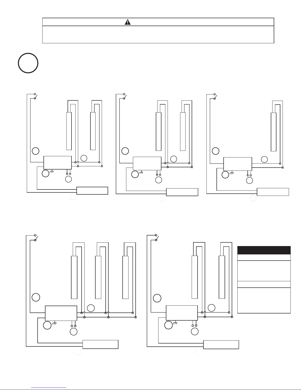
OPTION 1 – USING 3-WAY CONNECTO
Attach the supplied green/yellow ground wire from the
LED Driver to a grounded metal portion of the door frame.
Connect the original Line and neutral wires (or Line 1 and
Line 2 wires for 240 nominal VAC) to the 3-way connector
for the LED Driver input wires using the appropriate
matingconnector (Molex P/N 39-01-4030). Ensure that
the connector cavities are correctly populated per the
wire cavity table on page 5.
OPTION 2 – USING TWIST-ON WI E CONNECTO
Attach the supplied green/yellow ground wire from the
LED Driver to a grounded metal portion of the door frame.
Remove the 3-way connector from the LED Driver by cutting
the wires near the connector and strip the input wires. Using
the appropriate wiring diagram on page 5, connect the
original Line and neutral wires (or Line 1 and Line 2 wires for
240 nominal VAC) to the LED Driver leads using twist lock wire
connectors
or other connection method approved for low
temperature usage and stranded cable. Ensure that the
connector
cavities are correctly populated per wire cavity
table on page 5.
• Make input (AC) connections using one of the two options below:
• The LED Driver is required to be reliably bonded to the protective ground conductor.
• Make output (DC) connections using one of the two options below:
OPTION 1 – USING 4-WAY CONNECTO
Connect the LED Driver output leads to the LED Light leads
using the appropriate mating connector (Molex P/N 39-01-
4046). Terminals
installed should be crimped using approved
tooling and process per Molex specifications. Ensure that the
connector cavities are correctly populated per the
wire cavity table on page 5.
OPTION 2 – USING TWIST-ON WI E CONNECTO S
Remove the 4-way connector from the LED Driver by
cutting the wires near the connector and strip the output
leads. Using the appropriate wiring diagram on page 5,
connect the LED Driver output leads to the LED Light leads
using wire connectors or other connection method approved
for low temperature usage and stranded cable. (A)
For non-dimming applications, cap the unused wires with
4mm (5/32") twist on wire connectors.
OPTION 1 – USING 4-WAY CONNECTO
Connect the LED Driver dimming output leads to the
occupancy sensor or control system using the appropriate
mating connector (Molex P/N 39-01-4046). Terminals installed
should be crimped using approved tooling and process per
Molex specifications. Ensure that the connector cavities are
correctly populated per the wire cavity table on page 5.
(D)
OPTION 2 – USING TWIST-ON WI E CONNECTO S
Remove the 4-way connector from the LED Driver by
cutting the wires near the connector and strip the output
leads. Using the appropriate wiring diagram on page 5,
connect the LED Driver dimming output leads to the
occupancy sensor or control system using wire connectors
or other connection method approved for low temperature
usage and stranded cable. (D)
• To enable dimming operation, connect leads from occupancy sensor or control system (normally open contact) to the purple
and gray leads of the power supply.
• Make output (contact closure) connections using one of the two options below:
• The LED Driver is capable of step dimming from 100% power to 20% power when used with a normally
open contact closure
occupancy sensor system.
• When using the LED drivers for non-dimming applications, the dip switch setting must be set to #1 ON to
disable the dimming feature and achieve 100% illumination.
AA
C
D
B
C
D

LED efigerated Display Lights – Cleaning Instructions
• The outer lens and the plastic housing should be cleaned
periodically with a mild liquid dish detergent.
• Do not use chemical cleaners to clean the lens.
• eep the outside clean. Wipe with a clean cloth lightly
dampened with mild liquid dish detergent. Dry with a clean,
soft cloth.
• Do not wipe the lens with a soiled dish cloth or wet towel.
These may leave a residue that can damage the finish.
• Do not use scouring pads, powdered cleaners, bleach or
cleaners containing bleach because these products can
scratch and damage the finish.
11776-R110813
9
isk of electrical shock. Plastic cover is needed to protect electrical wires from tampering and accidental contact. / isque de choc électrique.
Le couvercle en plastique est requis pour assurer une protection adéquate contre l'accès aux fils et les contacts accidentels.
CAUTION / ATTENTION
7
isk of electrical shock. Disconnect power to LED Lights before any cleaning operation.
isque de choc électrique. Débranchez l'alimentation des éclairages à LED avant toute opération de nettoyage.
WARNING / AVERTISSMENT
Attach Covers to End Cap
• Tuck wires underneath Wire Cover before installing it onto
the End Cap.
• Attach Wire Cover to LED Light End Cap by inserting a
M2.9x10 pan head tapping screw (provided) through the
holes in Covers and Mounting Tabs using an installation
torque 0.32 N-m (3 lbf-in)
NOTE:
Tighten slowly until fully seated, do not over tighten
or strip the threads.
Wire
Cover
End Cap
M2.9x10 pan
head tapping
screw
8
GE Lighting Solutions • 1-888-MY-GE-LED • www.gelighting.com
1-8 88-6 9-43-533
GE Lighting Solutions, LLC is a subsidiary of the General Electric Company. Immersion is a trademark of GE Lighting Solutions, LLC. The GE brand and logo are trademarks of the General Electric Company.
© 2013 GE Lighting Solutions, LLC. Information provided is subject to change without notice. All values are design or typical values when measured under laboratory conditions.
This product is intended solely for the use of commercial refrigerated, display or case lighting and is not intended for use in
any other application.
This manual suits for next models
8
Table of contents
Other GE Lighting Lighting Equipment manuals
Popular Lighting Equipment manuals by other brands

EuroLite
EuroLite LED Z-3X3W RGB Beam Effect user manual

Verilux
Verilux HappyLight Liberty Series manual

KAM
KAM DMX Laser Tri 160 FScan instruction manual

Trilux
Trilux Inperla C2 HR LED 1100 Series Mounting instructions

CASARIA
CASARIA CWG001 instructions

GAME
GAME UNDERWATER LIGHT SHOW & FOUNTAIN 3567 instructions