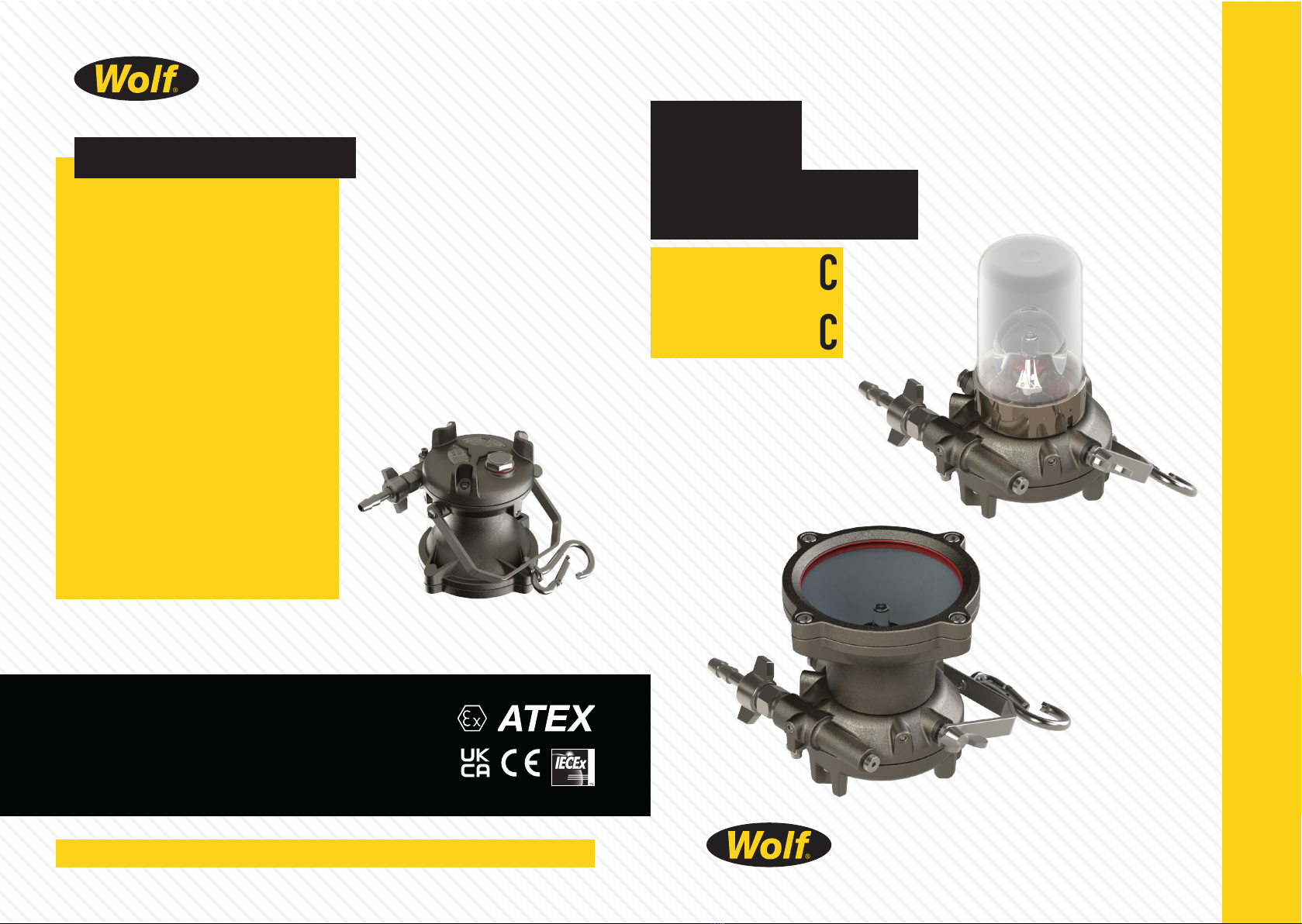
Wolf ATEX Turbolite – A-TL44C and A-TL45C
Operation and Maintenance Instructions
Please Retain - Read Before Use
EU Declaration of Conformity
The Wolf ATEX Turbolites A-TL44C and A-TL45C meet
all relevant provisions of the 2014/34/EU Explosive
Atmospheres (ATEX Equipment) Directive by virtue
of the issued EU type examination certicate,
demonstrating compliance with all relevant
harmonised standards and essential health and safety
requirements.
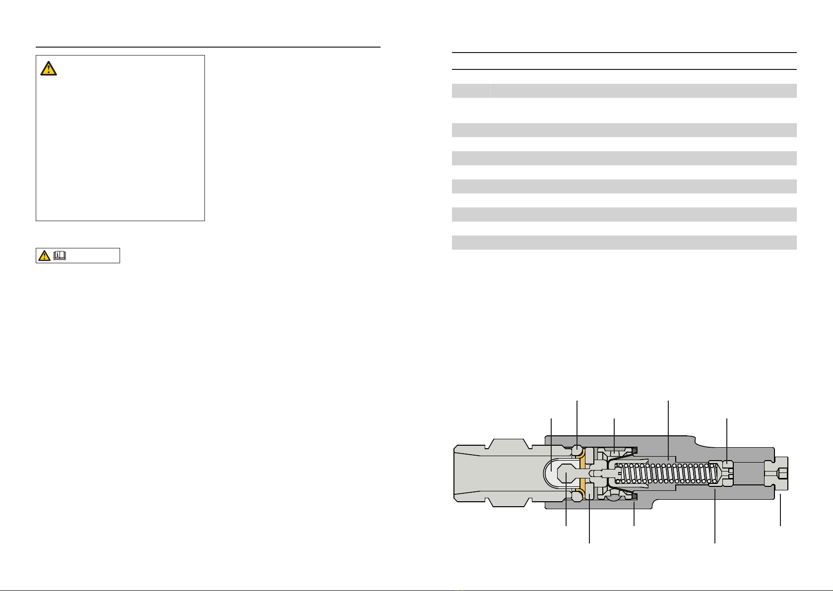
The Wolf ATEX Turbolite is powered with compressed
air that, once regulated, drives the turbine wheel
tted to the shaft. The magnet, also tted to the shaft,
rotates within windings, generating electricity and
powering a 24v 250watt tungsten halogen bulb. The
A-TL44C Baylight provides all round illumination; the
A-TL45C Floodlight gives directional illumination. Both
A-TL44C and A-TL45C models are constructed from
nickel plated aluminium.
The Wolf ATEX Turbolite is approved as Group II,
Category 2 equipment for use in zone 1, 2, 21 & 22
potentially explosive gases, vapours, mists and dusts
where the T4 temperature class/135°C maximum
surface temperature permits. Note, additional
accessories are required for use in zone 21 & 22.
Certication/Approval Codes:
Ex sb IIC T4 Gb
Ex sb IIIC T135ºC Db (refer to special conditions for safe use)
A-TL44C Ta = -15°C to +55°C
A-TL45C Ta = -20°C to +55°C
EU Type examination certicate: CML 22ATEX9542X
Notied Body:
Notied Body Number: 0598
Harmonised standard: EN IEC 60079-0:2018 and
applied standard IEC 60079-33:2012
Ingress protection level:
IP66 (when running) to EN60529:1992.
IP40 (when not running, keep protected from ingress of
water/dust).
The Wolf ATEX Turbolite is compliant with the
2011/65/EU RoHS Directive to the harmonised standard
EN IEC 63000:2018.
This declaration is issued under the sole responsibility
of Wolf Safety Lamp Company.
Alex Jackson – Managing Director,
Wolf Safety Lamp Company Ltd.,
Shefeld, S8 0YA.
Dated: 01 December 2023
II 2 G D
SGS FIMKO OY, PO Box 30 (Särkiniementie 3),
00211, Helsinki, Finland. IECEx Scheme Certification
Certicate Number: IECEx CML 22.0083X
Ex sb IIC T4 Gb
Ex sb IIIC T135ºC Db (refer to special conditions for safe use)
A-TL44C Ta = -15°C to +55°C
A-TL45C Ta = -20°C to +55°C
Ingress protection level:
IP66 (when running) to EN60529:1992
IP40 (when not running, keep protected from ingress of water/dust)
IEC Standards applied: IEC60079-0:2017, IEC60079-33:2012
IMPORTANT: SPECIAL CONDITIONS FOR SAFE USE (X)
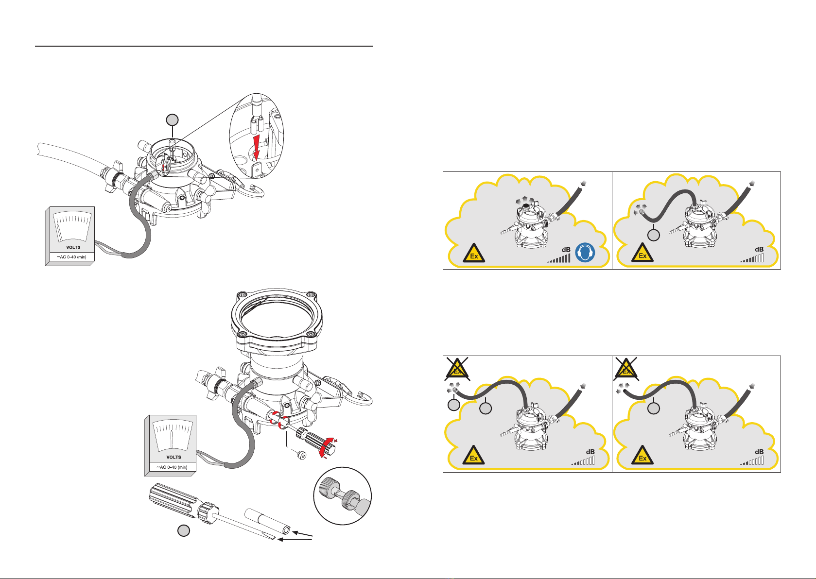
1. This equipment shall only be supplied with air from
a clean, dry source that is free from contamination with
hazardous gas, dust or bres.
2. When this equipment is used in the presence of
combustible dust, the air outlet shall be tted with
additional hose so that it is piped to a safe area instead of
venting into the hazardous area.
3. The hoses that are tted to this equipment shall be
anti-static with a resistance between 104 Ω and 108 Ω.
UK Declaration of Conformity
The Wolf ATEX Turbolites A-TL44C and A-TL45C meet
all the statutory requirements of the Equipment and
Protective Systems Intended for Use in Potentially
Explosive Atmospheres Regulations 2016, UKSI 2016/1107
as amended by UKSI 2019/696 by virtue of the issued
UKEX type examination certicate, demonstrating
compliance with all relevant designated standards and
essential health and safety requirements.
Certication/Approval Code:
Ex sb IIC T4 Gb
Ex sb IIIC T135ºC Db (refer to special conditions for safe use)
A-TL44C Ta = -15°C to +55°C
A-TL45C Ta = -20°C to +55°C
UK Type examination certicate: CML 22UKEX9543X
Approved Body:
Approval body number: 1180
Designated standard: EN IEC 60079-0:2018 and applied
standard IEC 60079-33:2012.
The Wolf ATEX Turbolite is compliant with the Restriction
of the Use of Certain Hazardous Substances in Electrical
and Electronic Equipment Regulations 2012, UKSI
2012/3032 to the harmonised standard EN IEC 63000:2018.
This declaration is issued under the sole responsibility of
Wolf Safety Lamp Company.
Alex Jackson – Managing Director,
Wolf Safety Lamp Company Ltd.,
Shefeld, S8 0YA.
Dated: 01 December 2023
SGS Baseefa Ltd, Rockhead Business Park,
Staden Lane, Buxton, SK17 9RZ, UK.
II 2 G D
1 10
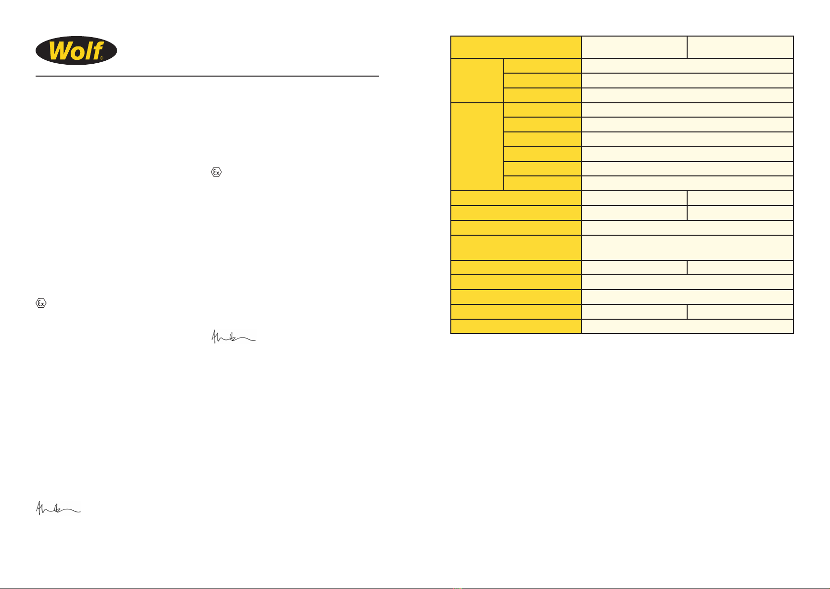
TECHNICAL DATA A-TL44C A-TL45C
Power Source Type Compressed Air Driven Turbo-Alternator Generator
Input Pressure Range 5-8 Bar
Consumption 0.75m³ / min.
Light Source Part Number A-129 (6,000lm, supplied as standard) / A-159 (9,000lm, alternative)
Type Halogen Filled Filament Bulb
Voltage 24V
Wattage 250W
Lumen Output 6,000lm / 9,000lm
Life 2,000hrs / 200hrs
Beam Type 360° Illumination 25° Flood
Lens Lens Ball Glass / Plastic Dome Toughened Glass
Enclosure Nickel Plated Aluminium
Ingress Protection IP66 when running*
IP40 when not running
Weight 4.4kg 5.3kg
Gas Temperature Class T4
Dust Surface Temperature T135°C
Lower Ambient Temp Limit -15°C -20°C
Upper Ambient Temp Limit 55°C
Wolf Safety Lamp Co. reserves the right to change technical specications without prior notice.
*Once pressurised, lamp may be used underwater. When using under water always start lamp
before submersing and ensure lamp is running until removed from water. Remote exhaust can be
used above water surface to eliminate bubbles. Depth of use limitations to be considered regarding
water pressure.
Disposal of Waste Material:
Disposal of packaging, parts and end of life products should be carried out in accordance with
applicable regulations.
The Wolf Safety Lamp Co. Ltd has a policy of continuous product improvement. Changes in design
details may be made without prior notice. Prices and design are subject to alteration without
notice. All products sold are subject to our conditions of sale. A copy of these instructions with any
relevant revisions can be found at www.wolfsafety.com.