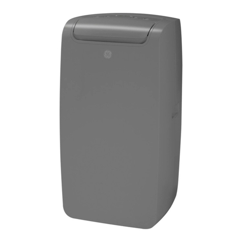
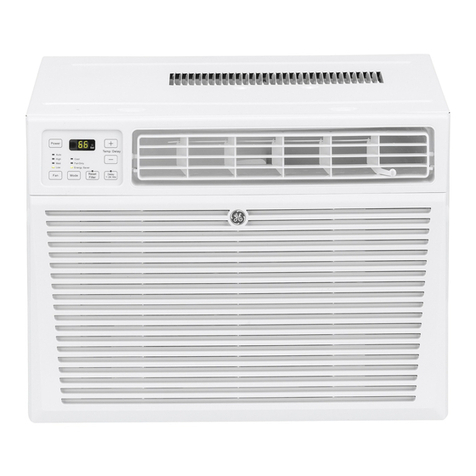
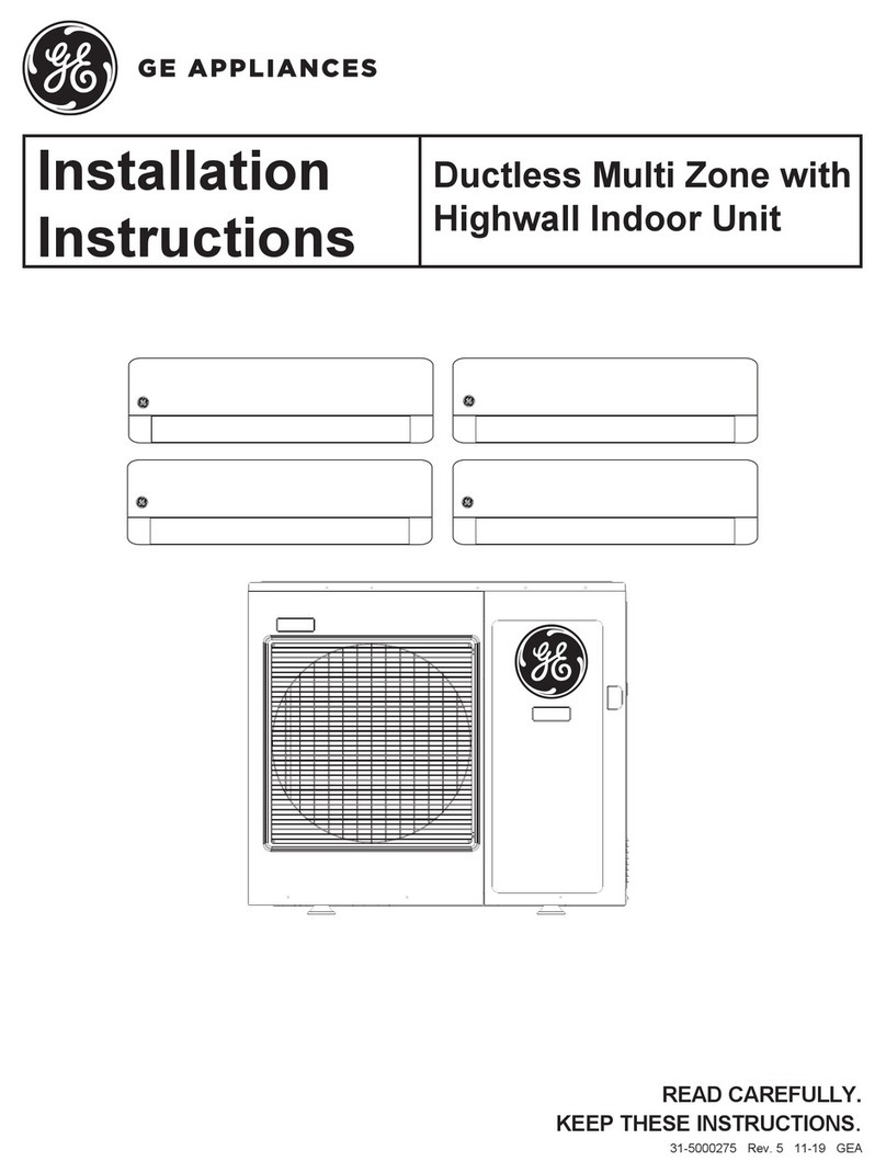
GE AIR 116 IN User manual

GE Consumer & Industrial Appliances
Service Manual & Installation Manual
Split System Air Conditioner
Model numbers:
GE AIR 116
GE AIR 121


11
11
1
MODEL REMARK
GE AIR 116 IN / GE AIR 116 OUT
GE AIR 121 IN / GE AIR 121 OUT 1PH 220V-230V
50Hz R407C
1Summary and Features

22
22
2
2Technical and Specification
Cooling Heating Cooling Heating
(W) 4600 5300 5900 6600
(W) 1750 1750 2200 2500
(W) 2200 2300 2500 2800
(A) 9.8 10.2 11.1 12.4
(m
3
/h)
(L/h)
(W/W) 2.82 2.82 2.68 2.64
Sound Power Level dB (A)
NetWeight/Gross Weight (kg) 12
Dimension (W/D/H)(mm) 907X290 X195
Fuse(A)
PCB3.15A Transformer0.2A
Sound Pressure Level dB (A)
48
Swing Motor Model
MP28GD
OutputPower of Swing
2
Row-Fin Gap(mm)
3-1.6/2-1.5
Developeed Area ofHeat
Exchanger(I XH XL)(mm2)730X400X40
Evaporator
Aluminum Fin-Copper tube
Pipe Diameter
Φ
7
Diameter-Length(mm)
φ
90 X723
Fan Type-piece
Cross-flow Fan—1
Fan Motor Running Current
0.091/0.067A
Fan Capacitor
1
OutputPower of Fan(W)
20
Indoor
Unit
Dimension ofPackage 1058X366 X317
55
Fan Speed(r/min)(H/M/L)
1250/1150/1050
Assistant Electric Heater
Power /
DehumidityVolume 1.8
C.O.P/ EER
Model
GE AIR 116 IN
Rated Power
Rated Current
Air Volume 700/670/620
Rated Frequency 50Hz
Capacity
Nominal Power
Model GE AIR 116 IN / GE AIR 116 OUT
Function
Rated Voltage 230V~
GE AIR 121 IN /GE AIR 121 OUT
230V~
50Hz
720
2
GE AIR 121 IN
1400/1200/1100
20
/
1
0.091/0.087A
Cross-flow Fan—1
φ
90X723
Aluminum Fin-Copper tube
Φ
7
3-1.6/2-1.5
606X230X25.4
MP28GD
2
PCB3.15A Transformer 0.2A
12
48
58
907X290 X195
1058X366 X317

33
33
3
GE AIR116 OUT GE AIR 121 OUT
CHZ33LC4-U CHW33TC4-U
Rotary Rotary
36 55
7.7A 9.8
1650W 2050W
Build in Build in
Capillary Capillary
Capacitor Capacitor
-7℃≤T≤43℃-7℃≤T≤43℃
Aluminum fin-copper tube Aluminum fin-copper tube
φ9.52 φ9.52
2-1.8 2-1.5
670mm X650X47mm 683mm X813X44mm
780 815
68 60
0.3A 0.31/0.30A
33.5
2400 2400
Axial fan –1 Axial fan –1
φ460 φ460
Auto defrost Auto defrost
T1 T1
II
IP24 IP24
2.7 2.5
0.4 0.6
60 60
68 69
950X700 X412 950X840 X412
1100X755 X450 1100X920 X450
59 72
R407C/1.8 R407C/2.4
55
Liquid (mm) φ9.52(3/8 ”) φ9.52(3/8”)
Gas (mm) φ16(5/8 ”) φ16(5/8”)
Height (m) 55
Length (m) 10 10
Overload Protector
Throttling Method
Outputof Fan Motor (W)
Fan Motor RLA
Developed Area of Heat
Exchanger(IXH XL)(mm2)
Fan Motor Speed (rpm)
Fan Motor Capacitor (uF)
Model of Outdoor Unit
Compressor Model
Compressor Type
L.R.A.(A)
Starting Method
Compressor RLA
Compressor Power Input
Pipe Diameter (mm)
Rows-Fin Gap(mm)
Air Flow Volume of Outdoor
Fan Type-Piece
Fan Diameter (mm)
Defrosting Method
Climate Type
Isolation
Moisture Protection
PermissibleExcessive
Sound Pressure Level dB (A)
Sound Power Level dB (A)
Dimension (W/D/H)( mm)
Dimension ofPackage
NetWeight /Gross Weight (kg)
RefrigerantCharge (kg)
Connect-
ion Pipe
Length (m)
Outer
Diamete
Max
Distance
Outdoor
unit
Working Temp Range (℃)
Condenser

4
3
Indoor Unit Air Inlet
Air Outlet
Air Inlet
Air Outlet
Wraping Tape
Front Panel
Air Guide Louver
Water Drainage Pipe
Connecting Pipe
and Connecting
Wire
Air Outlet Grill
Remote Con-
troller
Power
Plug
Parts Name
Outdoor Unit

5
44
44
4..
..
.11
11
1
4
Left Outlet
Pipe Hole
Rear View
Ceiling
Right
Installation Dimension
Left
AirInlet
290
907
>20cm >20cm
>7cm
195
OutLine and Installation Dimension
Outline and Installation Dimension of Indoor Unit

6
Bolt
Nut
Spanner
Above600
Above 600
Less than600
Above 600
Unit: mm
572
378
412
700
950

7
5System Diagram
5.1
Gas-liquid Separator
Evapoarator
Cross-flow Fan
Main Capillary Strainer
Check Valve
Assistant Capillary
Condenser
Compressor
Refrigenrant Flow Direction when Heating
Refrigenrant Flow Direction when Cooling
Circuit Diagram of Cooling / Heating System
When the power is on, indoor and outdoor units will start to run. When the system operates in
cooling mode, the compressor sucks low-temperature, low-pressure refrigerant gas from indoor
evaporator, compresses and then discharges high-temperature, high-pressure refrigerant gas into
outdoor heat exchanger. With the help of axial-flow fan, the gas transfers heat with environment
and becomes high-pressure refrigerant liquid. The liquid is throttled by the capillary and changes
into low-temperature and low-pressure liquid and then flows into indoor heat exchanger. With the
help of centrifugal fan, the liquid evaporates into low-temperature refrigerant gas and indoor air is
cooled down. The refrigerant gas is sucked into the compressor and the cycle introduced above
goes on and on, and the demanded low temperature environment is maintained. When the system
operates in heating mode, 4-way valve changes its way and the refrigerant flows into the reversible
cycle as the cooling mode. The refrigerant transfers heat in the indoor heat exchanger, and sucks
heat from outdoor heat exchanger and forms the heat pump cycle. This cycle goes on and on, and
the demanded high temperature environment is maintained.

8
Circuit Diagram
6
GEAIR 116 IN / GE AIR 116 OUT
GE AIR 121 IN / GE AIR 121 OUT

9
7.1.2.1.2 Protection Function
Anti Freezing Protections
When the system tested anti-freezing protection, the compressor will stop, the outdoor fan will delay 15 seconds and stop running .
Function Manual of Remote Controller
7
77
77
7..
..
.11
11
1Remote Controller Function Manual
7.1.2.2 Dry Mode
7.1.2.2.1 The condition and processes of dehumidifying
When Tamb Tset+2
, Dry and Cooling modes will act,compressor, outdoor fan will run at setting fan speed.
When Tset-2
Tamb
Tset+2
, Dry mode will act, at this time indoor fan runs at low fan speed,compressor will run 6mins and
will stop running, outdoor fan will delay 15s and stop. 3.45 mins later, compressor, outdoor fan and indoor fan motor restart
Over Current protection
When the system is tested, the compressor will stop, the outdoor fan will delay 15 seconds and stop running. The indoor fan will
run at the set speed. When antifreezing protection is eliminated and compressor has stopped for 3min, the system will resume
operation.
Compressor
Outdoor Fan
Indoor Fan
Min.
During anti-freezing
Stop
Running
Setting fan speed
7.1.1 Temperature Parameter
The room set temperature (Tset)
The room ambient temperature (Tamb)
7.1.2 System Fundamental functions
7.1.2.1 Cooling mode
If Tamb
Tset+1
, COOL mode will act, the compressor and the outdoor fan will run, the indoor fan will run at the setting speed.
If Tamb
Tset--
--
-1
, Compressor and outdoor fan will have a delay of 15 seconds and stop, indoor fan will run at the setting speed
If Tset-1
Tamb
Tset+1
, the unit will keep running in the old mode.
In this mode, the 4-way valve will not power on, the setting temp. range:16
~30
.
Start Cooling
Original Running Stat
e
Stop Cooling
set
set
amb
Min. Min. Min.
Setting Fan Speed
Stop
Running
Compressor
Outdoor Fan
Indoor Fan
˚
ć
ı
İ
˘
˘
ć
ć
ć
ć
ćć
ćİ
ćİ

10
7.1.2.2.2 Protection Function
Antifreezing protection
If the anti-freezing protection is detected, compressor,outdoor fan stop to run, indoor fan runs at low fan speed; When anti-
freezing is eliminated and compressor had stopped 3mins, the whole unit will back to original running state. When it isfit for the dry
mode running for 6mins and stop running for 4mins, and system anti-freezing protection is detected, thatthe compressor, outdoor
fan stop running, indoor fan runs at low fan speed, when anti-freezing is eleminated and compressorhad stopped for 4mins, that
will back to original running status.
7.1.2.3 Heating Model
7.1.2.3.1 Heating Running Condition and procedures
If Tamb Tset+2
, Heating mode will act, compressor, outdoor fan and 4-way valve will run, but indoor fan will run after 3minutes
delay.
If Tset+2
T amb
T set +4
, the unit will keep running in the original mode. In this mode, the 4-way valve will be powered on,
the setting temp. range:16
~30
.
If Tamb>Tset+4
, compressor , outdoor fan stop running, the 4-wayvalve is power on, indoor fan will stop after 60s
In this mode, the 4-way valve will be powered on, the setting temp. range:16 ~30
.
When Tamb
Tset-2
, compressor outdoor/indoorfan will stop.
In this mode, the 4-way valve won’t power on, the temperature range is 16
~30
.
7.1.2.3.2 Defrosting Condition and procedures
If frost is detected with the condenser, the system enters defrost mode.In this case, the compressor goes on running, outer fan,
4-way valve and inner fan stop running, the running indicator flash; If Swing is started, that the swing motor will stop torun at the
same time. After the condenser is detected with defrost completed, the outer fan, four-way valve will start torun at the same time,
indoor fan will go into running after a delay of 3mins. The swing motor will resume to run after indoorfan is running, compressor
keeps on original running mode, the running indicator stops flashing.
Indoor Fan
Outdoor Fan
Compressor
Cooling
Dehumidifying
Stop
SET
SET
amb
Running Stop
Min.
Min.
Min.
Min.
Seeting Fan Speed Low Fan Speed
Min.
amb
set
set
Min. Min.
Compressor
Outdoor Fan
Indoor Fan
4-way valve
Min.
Setting Fan Speed
Running Stop
Setting Fan Speed
Min.
Stop Heating
Original Running State
Start Heating
Indoor Fan
Outdoor Fan
Compressor
Stop
Running
Min
During anti-freezing
Low Fan Speed
˘
ć
˘
ć
ć ć
ć
ć
ć
ć
ć
˘˘
ćć

11
7.1.2.3.3 Protection Function
Anti-high temperature protection
when detecting evaporator tube is very high, outdoor fan will stop running; when detecting temperature is normal, outdoor fan will
return to run.
Electrical Noise protection
When "RUN/STOP" is used to turn off the unit, the 4-way valve will delay 2min to stop, or there will be 2 minutes of delay in the
mode switching.
Over current protection
Over current protection is the same with the over current in Cool mode.
7.1.2.4 Fan mode
In Fan mode, only the indoor fan is running.
7.1.2.5 AUTO mode
In this mode, the system will automatically select its running mode based on the change of the ambient temperature (cooling, dry ,
heating and air supply) The protection function as HEAT/COOL mode.
7.1.3 Other control
7.1.3.1 Sleep Function
In Cooling or Dry mode, when the set sleeping has run for 1 hour, Tset will rise 1
; 2 hours later, Tset will rise 2
.
The defrosting time is 10min for the first time power on and the defrosting time afterwards depends on the practicalfrost condition,
the more the frost, the longer the defrosting time(Max. 12min. Min. 3min), Exit from the defrostingmode if the frost removal is ended.
In Heating mode, when the set sleeping has run for 1 hour, Tset will decrease 1
; 2 hours later, Tset will decrease 2
..
..
.
The temp. has decreased 2
within two minutes. Then the unit will run at this setting temperaure.
7.1.3.2 Swing motor control
After the power is turned on, the stepping motor will return back to 0 position and close the air outlet vent;After the power is turned
on, if there is no Swing function be set, the up and down guide louvers will turnto horizontal position. In case when unit is turned
on, Sing function is set at the same time, that the guide louver will swing between L and D. When unit is turned off, the guide louver
will be turned off. Indoorfan will stop to run, guide louver will stop at once at the current position, and stop swing; after indoor fan
resumed to runthe guide louver will continue to swing.
Outdoor Fan Min. Min.
Min.
Compressor
Indoor Fan
4-way Valve
Running Stop
Druing Defrosting
Setting Temperature
Set
Set
Set
Set
hour hours
hour Above
Hour Hour Above Hour
Set
Set
Set
Setting temperature
Set
The set temperature of the sleep function of the auto mode does not change.
ć
ć
ćć
ć

12
7.1.3.3 Buzzer
When controller is power on or receives the signal from the wireless remote control, the buzzer will send out the sound once.
7.1.3.4 Indicator light
The running indicator is red, when unit is turned on, red indicator will be turned on, when defrosting, the indicatorwill flash. When
Timer is set, the yellow indicator will flash.
7.1.3.5 Auto fan control
In this mode, according to ambient temperature, indoor fan will select High, Middle, Low fan speed automatically. the interval of
each speed is 3 minutes and 30 seconds.
7.1.3.6 Auto button
When pressing this button, unit will run in Auto mode, indoor fan will run at Auto fan speed, the indoor fan is working,the swing
motor is running, when repressed this button, the unit will be turned off.

13
7.2 Operation method of remote controller
Note:
ON/OFF button
Press this button, the unit
will start to run, when re-
pressed it, it will stop
running.
FAN speed button
Press this button to
change the fan speed
Auto Fan
(Note:in“ ”mode,fanspeedcannot
beadjusted.
“ ” HEAT mode
Swing button
When it is pressed, the louvers
start to swing at the stated angle
and stop when repressed.
TEMP button
When pressing the Button, the
settingtemperaturewillbeincreasedby
1degreecentigrade,when pressingthe
button, the setting temperature
will be decreased 1 degree centigrade,
In “ ”mode, the
temperature could be adjusted in 16
degree centigrade-30 degree centi-
grade
MODE button
Press down the mode buttons in
turn the running modes will be
changed as follows:
Auto
Be sure that there are no obstructions between receiver and remote controller.
“ ” COOl mode
“ ” DRY mode
“ ” FAN mode

14
7.3 Names and functions of remote controller (with the cover removed)
Note:This type of remote controller is new current control. Some buttons AIR, HUMID, ANION,
SAVE, LIGHT of the control are not available for this type of air conditioner
Liquid crystal display It
shows all set contents
SLEEPbutton
Press this button to set SLEEP opera-
tion and stop when repressed.
Remarks: there is no SLEEP function
inAUTO and FAN mode.
Light button
The display will be lit each time the button is
pressed and the display will be distinguished
when the button is pressed once more.
T-OFFbutton
At operating mode, pressthis
button to set TIMEROFF in the
range of 0-24h
024h
Cancel
T-OFFbutton
At operating mode, press
this button to set TIMEROFF
in the range of 0-24h
024h
Cancel

15
_
+
_
+
7.4 Installation of battery for remote controller
Guide for operation procedure
The general procedure:
1.Plug to power supply and press ON/OFF button to start the unit.
2.Press MODE button to select the suitable operation mode.
3.Press SWING button to swing according to a certain direction and stop whenpressing it again.
4.Press FAN button to set desired fan speed.
5.Press button to set desired temperature.
The selected procedure:
6.Press SLEEP button to set the sleep.
7.Press TIMER button, then press The selected procedure:button to set scheduled time.
Note: In AUTO mode, the unit will automatically adjust its running modes accordingto the room temperature
changes.
The remote control adopts two 7# alkaline dry-cell batteries.
1.Remove the cover from the back of the remote control and insert two newbatteries (Pay
more attention to the polarity.)
2.Re-attach the cover.
How to insert batteries
Note:
Don’t mix new and used ordifferent types of
batteries.
Remove batteries away whenthe remote
control is not inuse for a long time.
The remote control should beplaced about 1m
or more awayfrom the TV set or any
otherelectric appliances.
It should be in it's receivingrange.
Reset Button Insert
two 7# batteries
Cover of
Batteries

16
8.1.1 Disassemble the front panel
Fig.8-1
Operation procedures/pictures
8.1 Disassembly procedures for indoor unit
Along the direction of arrow head,to take out
the panel.
As show in Fig.8-1
Push the filter inward, then pull the filterupward
can disassemble the filter.Loosen each movable
latch of the guidelouver, can disassemble the
guide louver.
As show in Fig.8-2 Fig.8-2
Disassembly procedures
8
Front panel
Filter
8.1.2 Disassemble the filter
Fig.8-3
Screw
Screw
Air guide louver
Electric box cover
Screw off the screw on the electric box cover
Open the 3pcs screw cover of front panel body,
then screw off 3pcs screw, then to pull out the
movable latch on the front panel, can
disassemblethe front panel.
As show in Fig.8-3
8.1.3 Disassemble the front panel body

17
Operation procedures/pictures
8.1.4 Disassemble water tray
Fig.8-4
To take the movable latch of water tray and the
wire terminal that connect withelectric box, then
lift up the water tray,take out the swing motor
wire, can dis-assemble the water tray.
As show in Fig.8-4
Remove the grounding wire of the evaporator,
and remove the temperature sensor for the pipe.
Remove the socket/plug connector for the in-
door motor and swing motor of the electric box.
Screw off the screws fixing the electric box with
a screw driver. Remove the electric box.
As shown in Fig.8-5, 8-6 Fig.8-5
Fig.8-6
Water tray
8.1.5 Disassemble electric box
Tube sensor
Room sensor
Screw
Movable latch Motor wire
Hook
Screw
This manual suits for next models
3
Table of contents
Other GE Air Conditioner manuals

GE
GE AKV12 and Operating instructions

GE
GE AEL08LP Assembly instructions

GE
GE AGL06 Operating instructions

GE
GE ASV18DL Manual

GE
GE ARC15AAC Series User manual

GE
GE ASM14 Operating instructions

GE
GE AGM10AJ User manual

GE
GE AGM12AB User manual

GE
GE Carry-Cool ATX04 Installation instructions

GE
GE AE0CD20DM Manual

GE
GE AJ806L Installation instructions

GE
GE ASV18DK Manual

GE
GE CLIMATISEUR AEH18* Operating instructions

GE
GE Appliances AEE24 Operating instructions

GE
GE AEM12AM Assembly instructions

GE
GE AHTC05AA User manual

GE
GE Porta-Cool KTP06 Installation instructions

GE
GE AJCQ08ACB User manual

GE
GE AEH12AP Operating instructions

GE
GE AJCH 08 ACB Operating instructions